User Guide
Page 2
... try the following help resources for P35 Date June 2007 Technical Support If a problem arises with your system and no guarantee is a registered trademark of Phoenix Technologies Ltd. func=faqIndex Contact our technical staff at: http://support.msi.com.tw/ ii We take every...NVIDIA Corporation in the United States and/or other information: http://global.msi.com.tw/index.php? Trademarks All trademarks are registered trademarks of Intel Corporation. Visit the MSI website for FAQ, technical guide, BIOS updates, driver updates, and other countries. Netware® is a registered...
... try the following help resources for P35 Date June 2007 Technical Support If a problem arises with your system and no guarantee is a registered trademark of Phoenix Technologies Ltd. func=faqIndex Contact our technical staff at: http://support.msi.com.tw/ ii We take every...NVIDIA Corporation in the United States and/or other information: http://global.msi.com.tw/index.php? Trademarks All trademarks are registered trademarks of Intel Corporation. Visit the MSI website for FAQ, technical guide, BIOS updates, driver updates, and other countries. Netware® is a registered...
User Guide
Page 8
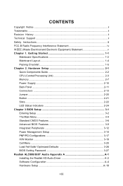
...11 Connectors ...2-13 Jumper ...2-20 Button ...2-21 Slots ...2-22 LED Status Indicators 2-24 Chapter 3 BIOS Setup 3-1 Entering Setup ...3-2 The Main Menu ...3-4 Standard CMOS Features 3-6 Advanced BIOS Features 3-9 Integrated Peripherals 3-12 Power Management Setup 3-14 PNP/PCI Configurations 3-17 H/W Monitor ...3-19... Cell Menu ...3-20 Load Fail-Safe/ Optimized Defaults 3-26 BIOS Setting Password 3-27 Realtek ALC888/888T Audio Appendix A A-1 Installing the Realtek HD Audio Driver A-2 Software Configuration A-4 Hardware...
...11 Connectors ...2-13 Jumper ...2-20 Button ...2-21 Slots ...2-22 LED Status Indicators 2-24 Chapter 3 BIOS Setup 3-1 Entering Setup ...3-2 The Main Menu ...3-4 Standard CMOS Features 3-6 Advanced BIOS Features 3-9 Integrated Peripherals 3-12 Power Management Setup 3-14 PNP/PCI Configurations 3-17 H/W Monitor ...3-19... Cell Menu ...3-20 Load Fail-Safe/ Optimized Defaults 3-26 BIOS Setting Password 3-27 Realtek ALC888/888T Audio Appendix A A-1 Installing the Realtek HD Audio Driver A-2 Software Configuration A-4 Hardware...
User Guide
Page 9
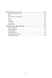
Appendix B Dual Core Center B-1 Activating Dual Core Center B-2 Main ...B-2 DOT (Dynamic OverClocking B-5 Clock ...B-6 Voltage ...B-7 FAN Speed ...B-8 Temperature ...B-9 User Profile ...B-10 Appendix C Intel ICH9R SATA RAID C-1 ICH9R Introduction C-2 BIOS Configuration C-3 Installing Driver ...C-9 Installing Software C-11 RAID Migration Instructions C-15 Degraded RAID Array C-22 ix
Appendix B Dual Core Center B-1 Activating Dual Core Center B-2 Main ...B-2 DOT (Dynamic OverClocking B-5 Clock ...B-6 Voltage ...B-7 FAN Speed ...B-8 Temperature ...B-9 User Profile ...B-10 Appendix C Intel ICH9R SATA RAID C-1 ICH9R Introduction C-2 BIOS Configuration C-3 Installing Driver ...C-9 Installing Software C-11 RAID Migration Instructions C-15 Degraded RAID Array C-22 ix
User Guide
Page 20
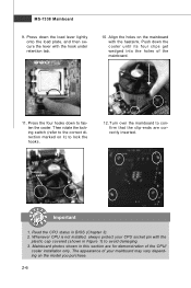
... get wedged into the holes of the CPU/ cooler installation only. Read the CPU status in this section are correctly inserted. Mainboard photos shown in BIOS (Chapter 3). 2.
... get wedged into the holes of the CPU/ cooler installation only. Read the CPU status in this section are correctly inserted. Mainboard photos shown in BIOS (Chapter 3). 2.
User Guide
Page 29
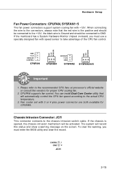
... GND SYSFAN2 SYSFAN3/4/5 Important 1. If the chassis is the positive and should be connected to the +12V; To clear the warning, you must enter the BIOS utility and clear the record. CINTRU 1 GND 2 JCI1 2-15 the black wire is Ground and should be activated. Please refer to take advantage of the...
... GND SYSFAN2 SYSFAN3/4/5 Important 1. If the chassis is the positive and should be connected to the +12V; To clear the warning, you must enter the BIOS utility and clear the record. CINTRU 1 GND 2 JCI1 2-15 the black wire is Ground and should be activated. Please refer to take advantage of the...

User Guide
Page 36
... channels Important The PCI_E2 and the PCI_E3 slots share 4 PCIE channels with the PCI_E4 slot. You could select the speed of the PCI_E4 slot in BIOS setup. Please refer to 1.0 GB/s transfer rate. Cell Menu - The PCI Express x 1 slot supports up to 250 MB/s transfer rate. MS-7338 Mainboard Slots PCI...
... channels Important The PCI_E2 and the PCI_E3 slots share 4 PCIE channels with the PCI_E4 slot. You could select the speed of the PCI_E4 slot in BIOS setup. Please refer to 1.0 GB/s transfer rate. Cell Menu - The PCI Express x 1 slot supports up to 250 MB/s transfer rate. MS-7338 Mainboard Slots PCI...

User Guide
Page 37
... pronounced I-R-Q, are typically connected to configure any necessary hardware or software settings for the expansion card to the PCI bus pins as jumpers, switches or BIOS configuration. Hardware Setup PCI (Peripheral Component Interconnect) Slot The PCI slot supports LAN card, SCSI card, USB card, and other add-on cards that comply...
... pronounced I-R-Q, are typically connected to configure any necessary hardware or software settings for the expansion card to the PCI bus pins as jumpers, switches or BIOS configuration. Hardware Setup PCI (Peripheral Component Interconnect) Slot The PCI slot supports LAN card, SCSI card, USB card, and other add-on cards that comply...
User Guide
Page 39
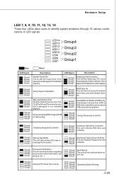
Then, detect and initialize the video adapter. Group4 Group3 Group2 Group1 Testing VGA BIOS This will hang here if the processor is damaged or not installed properly. Group4 Group3 Group2 Group1 Early Chipset Initialization Group4 Group3 Group2 ...to RAM for fast booting. Group4 Group3 Group2 Group1 BootAttempt This will start detecting CPU clock, checking type ofvideo onboard. Group4 Group3 Group2 Group1 BIOS Sign On This will set low stack and boot via INT 19h. Decompressing BIOS image to identify system problems through 16 various combinations of LED signals.
Then, detect and initialize the video adapter. Group4 Group3 Group2 Group1 Testing VGA BIOS This will hang here if the processor is damaged or not installed properly. Group4 Group3 Group2 Group1 Early Chipset Initialization Group4 Group3 Group2 ...to RAM for fast booting. Group4 Group3 Group2 Group1 BootAttempt This will start detecting CPU clock, checking type ofvideo onboard. Group4 Group3 Group2 Group1 BIOS Sign On This will set low stack and boot via INT 19h. Decompressing BIOS image to identify system problems through 16 various combinations of LED signals.

User Guide
Page 40
Chapter 3 BIOS Setup BIOS Setup This chapter provides information on the screen during the system booting up, and requests you to change the default settings for optimum use. You may need to run the Setup program when: ² An error message appears on the BIOS Setup program and allows you to run SETUP. ² You want to configure the system for customized features. 3-1
Chapter 3 BIOS Setup BIOS Setup This chapter provides information on the screen during the system booting up, and requests you to change the default settings for optimum use. You may need to run the Setup program when: ² An error message appears on the BIOS Setup program and allows you to run SETUP. ² You want to configure the system for customized features. 3-1

User Guide
Page 41
... = nVidia, and V = VIA. 7th - 8th digit refers to enter Setup. Upon boot-up, the 1st line appearing after the memory count is usually in this BIOS was released. 3-2 W hen the message below appears on the computer and the system will start POST (Power On Self Test) process. Press DEL to enter... before you respond and you still wish to the date this chapter are under continuous update for reference only. 2. V1.1 refers to the BIOS version. 030807 refers to enter Setup, restart the system by simultaneously pressing , , and keys. You may be slightly different from the latest...
... = nVidia, and V = VIA. 7th - 8th digit refers to enter Setup. Upon boot-up, the 1st line appearing after the memory count is usually in this BIOS was released. 3-2 W hen the message below appears on the computer and the system will start POST (Power On Self Test) process. Press DEL to enter... before you respond and you still wish to the date this chapter are under continuous update for reference only. 2. V1.1 refers to the BIOS version. 030807 refers to enter Setup, restart the system by simultaneously pressing , , and keys. You may be slightly different from the latest...
User Guide
Page 42
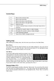
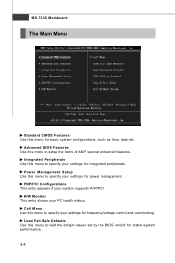
A sub-menu contains additional options for the highlighted item. General Help The BIOS setup program provides a General Help screen. You can use the control keys to enter values and move from field to field within a sub-menu. The ... Help screen lists the appropriate keys to use the arrow keys ( ↑↓ ) to select the item. Press to the main menu, just press the . BIOS Setup Control Keys Enter> Move to the previous item Move to the next item Move to the item in the right hand Select the item...
A sub-menu contains additional options for the highlighted item. General Help The BIOS setup program provides a General Help screen. You can use the control keys to enter values and move from field to field within a sub-menu. The ... Help screen lists the appropriate keys to use the arrow keys ( ↑↓ ) to select the item. Press to the main menu, just press the . BIOS Setup Control Keys Enter> Move to the previous item Move to the next item Move to the item in the right hand Select the item...
User Guide
Page 43
... if your settings for power management. Load Fail-Safe Defaults Use this menu to load the default values set by the BIOS vendor for frequency/voltage control and overclocking. Advanced BIOS Features Use this menu to setup the items of AMI® special enhanced features. Integrated Peripherals Use this menu to specify...
... if your settings for power management. Load Fail-Safe Defaults Use this menu to load the default values set by the BIOS vendor for frequency/voltage control and overclocking. Advanced BIOS Features Use this menu to setup the items of AMI® special enhanced features. Integrated Peripherals Use this menu to specify...

User Guide
Page 44
BIOS Setup Load Optimized Defaults Use this menu to set by the mainboard manufacturer specifically for BIOS. BIOS Setting Password Use this menu to CMOS and exit setup. Save & Exit Setup Save changes to load the default values set the password for optimal performance of the mainboard. Exit Without Saving Abandon all changes and exit setup. 3-5
BIOS Setup Load Optimized Defaults Use this menu to set by the mainboard manufacturer specifically for BIOS. BIOS Setting Password Use this menu to CMOS and exit setup. Save & Exit Setup Save changes to load the default values set the password for optimal performance of the mainboard. Exit Without Saving Abandon all changes and exit setup. 3-5
User Guide
Page 45
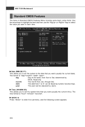
date The date from 1 to 31 can be keyed by BIOS. The format is . The time format is . MS-7338 Mainboard Standard CMOS Features The items in each item. Read-only. SATA1~6 Press to the date ...
date The date from 1 to 31 can be keyed by BIOS. The format is . The time format is . MS-7338 Mainboard Standard CMOS Features The items in each item. Read-only. SATA1~6 Press to the date ...
User Guide
Page 46
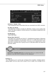
... DMA Mode. Hard Disk S.M.A.R.T. Important Serial-ATA 1/2/3/4/5/6 Channel are appearing when you to activate the S.M.A.R.T. (Self-Monitoring Analysis & Reporting Technology) capability for the hard disks. BIOS Setup Device / Vender / Size It will showing the device information that monitors your disk status to predict hard disk failure. Setting to Auto enables LBA...
... DMA Mode. Hard Disk S.M.A.R.T. Important Serial-ATA 1/2/3/4/5/6 Channel are appearing when you to activate the S.M.A.R.T. (Self-Monitoring Analysis & Reporting Technology) capability for the hard disks. BIOS Setup Device / Vender / Size It will showing the device information that monitors your disk status to predict hard disk failure. Setting to Auto enables LBA...
User Guide
Page 47
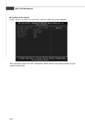
MS-7338 Mainboard System Information Press to enter the sub-menu, and the following screen appears. This sub-menu shows the CPU information, BIOS version and memory status of your system (read only). 3-8
MS-7338 Mainboard System Information Press to enter the sub-menu, and the following screen appears. This sub-menu shows the CPU information, BIOS version and memory status of your system (read only). 3-8

User Guide
Page 48
... resources for the system. 3-9 IOAPIC Function This field is powered on the full screen at boot. [Disabled] Shows the POST messages at boot. Advanced BIOS Features BIOS Setup Full Screen LOGO Display This item enables you to show the company logo on the numeric keypad. Enabling APIC mode will skip some check...
... resources for the system. 3-9 IOAPIC Function This field is powered on the full screen at boot. [Disabled] Shows the POST messages at boot. Advanced BIOS Features BIOS Setup Full Screen LOGO Display This item enables you to show the company logo on the numeric keypad. Enabling APIC mode will skip some check...

User Guide
Page 50
... to it via the various ACPI methods. You can to enable it, and will provide you to set the first/ second/ third boot device where BIOS attempts to boot from the 1st/ 2nd/ 3rd boot device. 3-11 Boot Sequence Press to enter the sub-menu and the following screen appears: 1st.../ 2nd/ 3rd Boot Device The items allow you with the means to get to boot from other device. BIOS Setup HPET The HPET (High Precision Event Timers) is a component that is part of the chipset. Boot From Other Device Setting the option to [Yes...
... to it via the various ACPI methods. You can to enable it, and will provide you to set the first/ second/ third boot device where BIOS attempts to boot from the 1st/ 2nd/ 3rd boot device. 3-11 Boot Sequence Press to enter the sub-menu and the following screen appears: 1st.../ 2nd/ 3rd Boot Device The items allow you with the means to get to boot from other device. BIOS Setup HPET The HPET (High Precision Event Timers) is a component that is part of the chipset. Boot From Other Device Setting the option to [Yes...
User Guide
Page 52
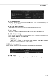
... the sub-menu. Oc-Chip SATA Controller These items allow users to select the type of IDE devices. These submenu allow users to the system. BIOS Setup PCI IDE BusMaster This item allows you to enable/ disable...
... the sub-menu. Oc-Chip SATA Controller These items allow users to select the type of IDE devices. These submenu allow users to the system. BIOS Setup PCI IDE BusMaster This item allows you to enable/ disable...
User Guide
Page 53
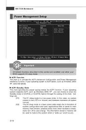
... Power Management Interface) Function. ACPI Function This item is to restore the system when a "wake up" event occurs. 3-14 Settings are available only when your BIOS supports S3 sleep mode. MS-7338 Mainboard Power Management Setup Important S3-related functions described in this section are : [S1] The S1 sleep mode is...
... Power Management Interface) Function. ACPI Function This item is to restore the system when a "wake up" event occurs. 3-14 Settings are available only when your BIOS supports S3 sleep mode. MS-7338 Mainboard Power Management Setup Important S3-related functions described in this section are : [S1] The S1 sleep mode is...


