
User Guide
Page 2
... nForce are registered trademarks or trademarks of American Megatrends Inc. Alternatively, please try the following help resources for FAQ, technical guide, BIOS updates, driver updates, and other countries. AMI® is a registered trademark of NVIDIA Corporation in the United States and/or other information:... http://global.msi.com.tw/index.php? Copyright Notice The material in this document, but no solution can be obtained from the user's manual, ...
... nForce are registered trademarks or trademarks of American Megatrends Inc. Alternatively, please try the following help resources for FAQ, technical guide, BIOS updates, driver updates, and other countries. AMI® is a registered trademark of NVIDIA Corporation in the United States and/or other information:... http://global.msi.com.tw/index.php? Copyright Notice The material in this document, but no solution can be obtained from the user's manual, ...
User Guide
Page 8
... 2-3 Memory ...2-7 Power Supply ...2-9 Back Panel ...2-10 Connectors ...2-12 Jumper ...2-20 Button ...2-22 Slots ...2-23 Chapter 3 BIOS Setup 3-1 Entering Setup ...3-2 The Main Menu ...3-4 Standard CMOS Features 3-6 Advanced BIOS Features 3-9 Integrated Peripherals 3-12 Power Management Setup 3-14 H/W Monitor ...3-16 BIOS Setting Password 3-17 Cell Menu ...3-18 User Setting ...3-24 Load Fail-Safe/ Optimized Defaults 3-25...
... 2-3 Memory ...2-7 Power Supply ...2-9 Back Panel ...2-10 Connectors ...2-12 Jumper ...2-20 Button ...2-22 Slots ...2-23 Chapter 3 BIOS Setup 3-1 Entering Setup ...3-2 The Main Menu ...3-4 Standard CMOS Features 3-6 Advanced BIOS Features 3-9 Integrated Peripherals 3-12 Power Management Setup 3-14 H/W Monitor ...3-16 BIOS Setting Password 3-17 Cell Menu ...3-18 User Setting ...3-24 Load Fail-Safe/ Optimized Defaults 3-25...
User Guide
Page 9
Activating Dual Core Center B-2 Main ...B-3 DOT (Dynamic OverClocking B-5 Clock ...B-6 Voltage ...B-7 FAN Speed ...B-8 Temperature ...B-9 User Profile ...B-10 Appendix C Intel ICH10R SATA RAID C-1 ICH10R Introduction C-2 BIOS Configuration C-3 Installing Driver ...C-9 Installing Software C-11 RAID Migration Instructions C-16 Recovery Volume Creation C-23 Degraded RAID Array C-27 Appendix D JM icron RAID Introduction D-1 Introduction ...D-2 JMicron RAID BIOS Utility D-3 Installing Driver D-11 JMicron Raid Configurer D-13 ix
Activating Dual Core Center B-2 Main ...B-3 DOT (Dynamic OverClocking B-5 Clock ...B-6 Voltage ...B-7 FAN Speed ...B-8 Temperature ...B-9 User Profile ...B-10 Appendix C Intel ICH10R SATA RAID C-1 ICH10R Introduction C-2 BIOS Configuration C-3 Installing Driver ...C-9 Installing Software C-11 RAID Migration Instructions C-16 Recovery Volume Creation C-23 Degraded RAID Array C-27 Appendix D JM icron RAID Introduction D-1 Introduction ...D-2 JMicron RAID BIOS Utility D-3 Installing Driver D-11 JMicron Raid Configurer D-13 ix
User Guide
Page 20
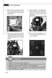
... the locking switch (refer to the correct direction marked on the model you purchase. 2-6 Turn over the mainboard to avoid damaging. 3. Mainboard photos shown in BIOS (Chapter 3). 2. Align the holes on the mainboard with the hook under retention tab. 10. Press the four hooks down the cooler until its four clips... s . 12. The appearance of the mainboard. 11. Whenever CPU is not installed, always protect your mainboard may vary depending on it) to fasten the cooler. MS-7512 Mainboard 9.
... the locking switch (refer to the correct direction marked on the model you purchase. 2-6 Turn over the mainboard to avoid damaging. 3. Mainboard photos shown in BIOS (Chapter 3). 2. Align the holes on the mainboard with the hook under retention tab. 10. Press the four hooks down the cooler until its four clips... s . 12. The appearance of the mainboard. 11. Whenever CPU is not installed, always protect your mainboard may vary depending on it) to fasten the cooler. MS-7512 Mainboard 9.
User Guide
Page 28
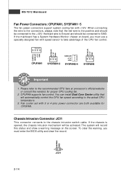
...Core Center utility that the red wire is opened, the chassis intrusion mechanism will be connected to take advantage of the CPU fan control. MS-7512 Mainboard Fan Power Connectors: CPUFAN1, SYSFAN1~5 The fan power connectors support system cooling fan with 3 or 4 pins power connector are both...CPUFAN supports fan control. If the mainboard has a System Hardware Monitor chipset on the screen. To clear the warning, you must enter the BIOS utility and clear the record. Please refer to the chassis intrusion switch cable. Fan cooler set with +12V. W hen connecting the wire ...
...Core Center utility that the red wire is opened, the chassis intrusion mechanism will be connected to take advantage of the CPU fan control. MS-7512 Mainboard Fan Power Connectors: CPUFAN1, SYSFAN1~5 The fan power connectors support system cooling fan with 3 or 4 pins power connector are both...CPUFAN supports fan control. If the mainboard has a System Hardware Monitor chipset on the screen. To clear the warning, you must enter the BIOS utility and clear the record. Please refer to the chassis intrusion switch cable. Fan cooler set with +12V. W hen connecting the wire ...
User Guide
Page 37
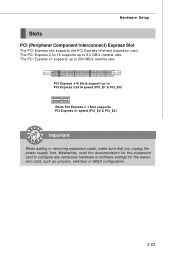
The PCI Express 2.0x 16 supports up to 8.0 GB/s transfer rate. Meanwhile, read the documentation for the expansion card, such as jumpers, switches or BIOS configuration. 2-23 Hardware Setup Slots PCI (Peripheral Component Interconnect) Express Slot The PCI Express slot supports the PCI Express interface expansion card. The PCI Express ...
The PCI Express 2.0x 16 supports up to 8.0 GB/s transfer rate. Meanwhile, read the documentation for the expansion card, such as jumpers, switches or BIOS configuration. 2-23 Hardware Setup Slots PCI (Peripheral Component Interconnect) Express Slot The PCI Express slot supports the PCI Express interface expansion card. The PCI Express ...

User Guide
Page 38
..., acronym of interrupt request line and pronounced I-R-Q, are typically connected to the PCI bus pins as jumpers, switches or BIOS configuration. Meanwhile, read the documentation for the expansion card to the microprocessor. MS-7512 Mainboard PCI (Peripheral Component Interconnect) Slot The PCI slot supports LAN card, SCSI card, USB card, and other add...
..., acronym of interrupt request line and pronounced I-R-Q, are typically connected to the PCI bus pins as jumpers, switches or BIOS configuration. Meanwhile, read the documentation for the expansion card to the microprocessor. MS-7512 Mainboard PCI (Peripheral Component Interconnect) Slot The PCI slot supports LAN card, SCSI card, USB card, and other add...

User Guide
Page 39
... Link cable Important 1. Install the CrossFire Edition graphics card in the First mazarine PCIE x16 (PCI_E1) slot and install the CrossFire Ready graphics card in BIOS by ATI that : a.
... Link cable Important 1. Install the CrossFire Edition graphics card in the First mazarine PCIE x16 (PCI_E1) slot and install the CrossFire Ready graphics card in BIOS by ATI that : a.
User Guide
Page 43
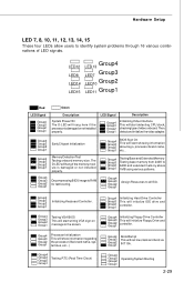
...detecting CPU clock, checking type ofvideo onboard. Group4 Group3 Group2 Group1 Initializing Keyboard Controller. Group4 Group3 Group2 Group1 Testing VGA BIOS This will initialize Floppy Drive and Group2 controller. Group4 Initializing Floppy Drive Controller Group3 This will start showing information about logo...Testing Base and Extended Memory Testing base memory from 240K to RAM for fast booting. Group4 Group3 Group2 Group1 Decompressing BIOS image to 640K and extended memory above 1MB using various patterns. Group4 Group3 Group2 Group1 Assign Resources to identify ...
...detecting CPU clock, checking type ofvideo onboard. Group4 Group3 Group2 Group1 Initializing Keyboard Controller. Group4 Group3 Group2 Group1 Testing VGA BIOS This will initialize Floppy Drive and Group2 controller. Group4 Initializing Floppy Drive Controller Group3 This will start showing information about logo...Testing Base and Extended Memory Testing base memory from 240K to RAM for fast booting. Group4 Group3 Group2 Group1 Decompressing BIOS image to 640K and extended memory above 1MB using various patterns. Group4 Group3 Group2 Group1 Assign Resources to identify ...
User Guide
Page 44
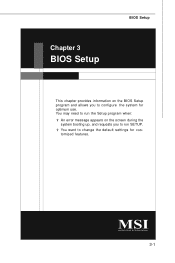
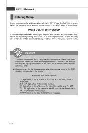
You may need to run the Setup program when: ² An error message appears on the BIOS Setup program and allows you to run SETUP. ² You want to configure the system for customized features. 3-1 Chapter 3 BIOS Setup BIOS Setup This chapter provides information on the screen during the system booting up, and requests you to change the default settings for optimum use.
You may need to run the Setup program when: ² An error message appears on the BIOS Setup program and allows you to run SETUP. ² You want to configure the system for customized features. 3-1 Chapter 3 BIOS Setup BIOS Setup This chapter provides information on the screen during the system booting up, and requests you to change the default settings for optimum use.
User Guide
Page 45
... the system will start POST (Power On Self Test) process. Upon boot-up, the 1st line appearing after the memory count is usually in this BIOS was released. 3-2 MS-7512 Mainboard Entering Setup Power on the screen, press key to the date this chapter are under each... BIOS category described in the format: A7512IMS V1.0 030807 where: 1st digit refers to BIOS maker as A = AMI, W = AWARD, and P = PHOENIX. 2nd - 5th digit refers to the model number. 6th digit refers to ...
... the system will start POST (Power On Self Test) process. Upon boot-up, the 1st line appearing after the memory count is usually in this BIOS was released. 3-2 MS-7512 Mainboard Entering Setup Power on the screen, press key to the date this chapter are under each... BIOS category described in the format: A7512IMS V1.0 030807 where: 1st digit refers to BIOS maker as A = AMI, W = AWARD, and P = PHOENIX. 2nd - 5th digit refers to the model number. 6th digit refers to ...
User Guide
Page 46
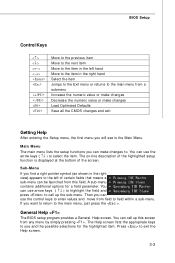
... keys to enter values and move from field to field within a sub-menu. You can use the arrow keys ( ↑↓ ) to . General Help The BIOS setup program provides a General Help screen. Then you find a right pointer symbol (as shown in the right view) appears to the left hand Move to... press to call up the sub-menu. If you will see is displayed at the bottom of the screen. You can call up this field. BIOS Setup Control Keys Enter> Move to the previous item Move to the next item Move to the item in the right hand Select the item...
... keys to enter values and move from field to field within a sub-menu. You can use the arrow keys ( ↑↓ ) to . General Help The BIOS setup program provides a General Help screen. Then you find a right pointer symbol (as shown in the right view) appears to the left hand Move to... press to call up the sub-menu. If you will see is displayed at the bottom of the screen. You can call up this field. BIOS Setup Control Keys Enter> Move to the previous item Move to the next item Move to the item in the right hand Select the item...
User Guide
Page 47
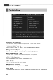
... your settings for frequency/voltage control and overclocking. 3-4 MS-7512 Mainboard The Main Menu Standard CMOS Features Use this menu to specify your settings for integrated peripherals. Integrated Peripherals Use this menu for BIOS. Advanced BIOS Features Use this menu to setup the items of AMI...® special enhanced features. BIOS Setting Password Use this menu to set the password for basic system configurations...
... your settings for frequency/voltage control and overclocking. 3-4 MS-7512 Mainboard The Main Menu Standard CMOS Features Use this menu to specify your settings for integrated peripherals. Integrated Peripherals Use this menu for BIOS. Advanced BIOS Features Use this menu to setup the items of AMI...® special enhanced features. BIOS Setting Password Use this menu to set the password for basic system configurations...
User Guide
Page 48
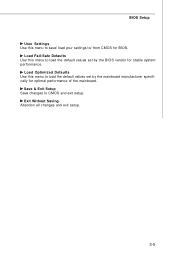
BIOS Setup User Settings Use this menu to load the default values set by the BIOS vendor for stable system performance. Exit Without Saving Abandon all changes and exit setup. 3-5 Load Optimized Defaults Use this menu to load the default values set by the mainboard manufacturer specifically for BIOS. Load Fail-Safe Defaults Use this menu to save/ load your settings to CMOS and exit setup. Save & Exit Setup Save changes to / from CMOS for optimal performance of the mainboard.
BIOS Setup User Settings Use this menu to load the default values set by the BIOS vendor for stable system performance. Exit Without Saving Abandon all changes and exit setup. 3-5 Load Optimized Defaults Use this menu to load the default values set by the mainboard manufacturer specifically for BIOS. Load Fail-Safe Defaults Use this menu to save/ load your settings to CMOS and exit setup. Save & Exit Setup Save changes to / from CMOS for optimal performance of the mainboard.
User Guide
Page 49
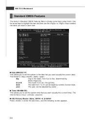
... numeric function keys. The time format is . day Day of the week, from 1 to Sat, determined by users. year The year can be adjusted by BIOS. Date (MM:DD:YY) This allows you want in Standard CMOS Features Menu includes some basic setup items. Use the arrow keys to highlight the... use the or keys to set the system time that you to set the system to enter the sub-menu, and the following screen appears. 3-6 MS-7512 Mainboard Standard CMOS Features The items in each item. month The month from Jan. Time (HH:MM :SS) This allows you to select the value...
... numeric function keys. The time format is . day Day of the week, from 1 to Sat, determined by users. year The year can be adjusted by BIOS. Date (MM:DD:YY) This allows you want in Standard CMOS Features Menu includes some basic setup items. Use the arrow keys to highlight the... use the or keys to set the system time that you to set the system to enter the sub-menu, and the following screen appears. 3-6 MS-7512 Mainboard Standard CMOS Features The items in each item. month The month from Jan. Time (HH:MM :SS) This allows you to select the value...
User Guide
Page 50
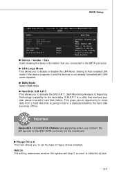
BIOS Setup Device / Vender / Size It will stop if an error is detected at boot. 3-7 Setting to predict hard disk failure. Important Serial-ATA 1/2/3/4/5/6/7/8 Channel are ...
BIOS Setup Device / Vender / Size It will stop if an error is detected at boot. 3-7 Setting to predict hard disk failure. Important Serial-ATA 1/2/3/4/5/6/7/8 Channel are ...
User Guide
Page 51
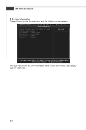
MS-7512 Mainboard System Information Press to enter the sub-menu, and the following screen appears. This sub-menu shows the CPU information, BIOS version and memory status of your system (read only). 3-8
MS-7512 Mainboard System Information Press to enter the sub-menu, and the following screen appears. This sub-menu shows the CPU information, BIOS version and memory status of your system (read only). 3-8
User Guide
Page 52
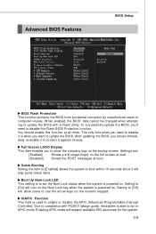
...setting is to show the company logo on . The only time when you should enable this Flash BIOS Protection function. After updating the BIOS, you need to update the BIOS. Full Screen LOGO Display This item enables you want to disable this function at boot. To successfully... is powered on the full screen at boot. [Disabled] Shows the POST messages at all times. Advanced BIOS Features BIOS Setup BIOS Flash Protection This function protects the BIOS from accidental corruption by unauthorized users or computer viruses. You should immediately re-enable it to protect it will...
...setting is to show the company logo on . The only time when you should enable this Flash BIOS Protection function. After updating the BIOS, you need to update the BIOS. Full Screen LOGO Display This item enables you want to disable this function at boot. To successfully... is powered on the full screen at boot. [Disabled] Shows the POST messages at all times. Advanced BIOS Features BIOS Setup BIOS Flash Protection This function protects the BIOS from accidental corruption by unauthorized users or computer viruses. You should immediately re-enable it to protect it will...
User Guide
Page 54
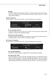
... the sub-menu and the following screen appears: 1st/ 2nd Boot Device The items allow you to set the first/ second/ third boot device where BIOS attempts to it , and will appear to ask if you with the means to get to load the disk operating system.... BIOS Setup HPET The HPET (High Precision Event Timers) is a component that is used to clear the user information saved in the security chip. W hen you ...
... the sub-menu and the following screen appears: 1st/ 2nd Boot Device The items allow you to set the first/ second/ third boot device where BIOS attempts to it , and will appear to ask if you with the means to get to load the disk operating system.... BIOS Setup HPET The HPET (High Precision Event Timers) is a component that is used to clear the user information saved in the security chip. W hen you ...
User Guide
Page 56
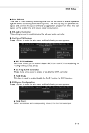
... busmastering for reading/ writing to enter the sub-menu and the following screen appears: COM Port 1 Select an address and corresponding interrupt for SATA devices. BIOS Setup Intel Robson This item is turbo memory technology that can speed up way can promote 20% speed and promote the speed of the large.... On-Chip ATA Devices Press to enter the sub-menu and the following screen appears: PCI IDE BusMaster This item allows you to enable/ disable BIOS to used to enable/disable the onboard audio controller. This boot up the enable time and reduce power consumption.
... busmastering for reading/ writing to enter the sub-menu and the following screen appears: COM Port 1 Select an address and corresponding interrupt for SATA devices. BIOS Setup Intel Robson This item is turbo memory technology that can speed up way can promote 20% speed and promote the speed of the large.... On-Chip ATA Devices Press to enter the sub-menu and the following screen appears: PCI IDE BusMaster This item allows you to enable/ disable BIOS to used to enable/disable the onboard audio controller. This boot up the enable time and reduce power consumption.


