
User Guide
Page 2
... Technical Support If a problem arises with your system and no guarantee is given as to make changes without notice. Visit the MSI website for further guidance. Copyright Notice The material in the preparation of this document is the intellectual property of M ICRO-STAR INTERNATIONAL. Alternatively, please try the following help resources for FAQ, technical guide, BIOS updates, driver updates, and...
... Technical Support If a problem arises with your system and no guarantee is given as to make changes without notice. Visit the MSI website for further guidance. Copyright Notice The material in the preparation of this document is the intellectual property of M ICRO-STAR INTERNATIONAL. Alternatively, please try the following help resources for FAQ, technical guide, BIOS updates, driver updates, and...
User Guide
Page 8
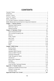
... Components Guide 2-2 CPU (Central Processing Unit 2-3 Memory ...2-7 Power Supply ...2-9 Back Panel ...2-10 Connectors ...2-12 Jumper ...2-20 Button ...2-22 Slots ...2-23 Chapter 3 BIOS Setup 3-1 Entering Setup ...3-2 The Main Menu ...3-4 Standard CMOS Features 3-6 Advanced BIOS Features 3-9 Integrated Peripherals 3-12 Power Management Setup 3-14 H/W Monitor ...3-16 BIOS Setting Password 3-17 Cell Menu ...3-18 User Setting ...3-24 Load Fail-Safe/ Optimized Defaults 3-25 Appendix A Realtek Audio A-1 Installing the Realtek HD Audio Driver A-2 Software Configuration A-4 Hardware Setup...
... Components Guide 2-2 CPU (Central Processing Unit 2-3 Memory ...2-7 Power Supply ...2-9 Back Panel ...2-10 Connectors ...2-12 Jumper ...2-20 Button ...2-22 Slots ...2-23 Chapter 3 BIOS Setup 3-1 Entering Setup ...3-2 The Main Menu ...3-4 Standard CMOS Features 3-6 Advanced BIOS Features 3-9 Integrated Peripherals 3-12 Power Management Setup 3-14 H/W Monitor ...3-16 BIOS Setting Password 3-17 Cell Menu ...3-18 User Setting ...3-24 Load Fail-Safe/ Optimized Defaults 3-25 Appendix A Realtek Audio A-1 Installing the Realtek HD Audio Driver A-2 Software Configuration A-4 Hardware Setup...

User Guide
Page 11
... http://global. c om . t w / index. Supports Ultra DMA 66/100/133 mode - Intel® CoreTM 2 Extreme/Quad/Duo, Pentinum® Dual-Core and Celeron® processors in the LGA775 package - Supports VoIP Card (only for ALC888T) IDE - 1 IDE port (only for Jmicron 363) - Flexible 8-channel audio with Azalia 1.0 Spec - Support Intel® Yorkfield, Wolfdale - Meet Microsoft Vista Premium spec - c om . Supports Intel Martix Storage Technology (AHCI + RAID 0/1/5/10) by ICH10R 1394 - MS-7512 Mainboard Mainboard Specifications Processor Support -
... http://global. c om . t w / index. Supports Ultra DMA 66/100/133 mode - Intel® CoreTM 2 Extreme/Quad/Duo, Pentinum® Dual-Core and Celeron® processors in the LGA775 package - Supports VoIP Card (only for ALC888T) IDE - 1 IDE port (only for Jmicron 363) - Flexible 8-channel audio with Azalia 1.0 Spec - Support Intel® Yorkfield, Wolfdale - Meet Microsoft Vista Premium spec - c om . Supports Intel Martix Storage Technology (AHCI + RAID 0/1/5/10) by ICH10R 1394 - MS-7512 Mainboard Mainboard Specifications Processor Support -
User Guide
Page 12
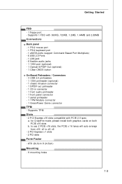
...) - 1 Clear CMOS button On-Board Pinheaders / Connectors - 3 USB 2.0 pinheaders - 1 1394 pinheader (optional) - 1 chasis intrusion connector - 1 SPDIF-out pinheader - 1 CD-in connector - 1 front audio pinheader - 1 front panel connector - 1 serial pinheader - 1 TPM Module connector - 1 GreenPower Genie connector TPM - for CrossFire mode, please install both graphics cards on both PCIE x16 slots b. ATX (30.5cm X 24.5cm) Mounting - 9 mounting holes 1-3 Getting Started FDD - 1 floppy port - to use 2 PCIE x16 slots, the PCIE x 16 lanes will auto arrange from x16/ x0 to x8/ x8 - 2 PCI Express...
...) - 1 Clear CMOS button On-Board Pinheaders / Connectors - 3 USB 2.0 pinheaders - 1 1394 pinheader (optional) - 1 chasis intrusion connector - 1 SPDIF-out pinheader - 1 CD-in connector - 1 front audio pinheader - 1 front panel connector - 1 serial pinheader - 1 TPM Module connector - 1 GreenPower Genie connector TPM - for CrossFire mode, please install both graphics cards on both PCIE x16 slots b. ATX (30.5cm X 24.5cm) Mounting - 9 mounting holes 1-3 Getting Started FDD - 1 floppy port - to use 2 PCIE x16 slots, the PCIE x 16 lanes will auto arrange from x16/ x0 to x8/ x8 - 2 PCI Express...
User Guide
Page 26
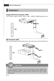
Refer to master / slave mode by the vendors for jumper setting instructions. 2-12 IDE1 Important If you install two IDE devices on the same cable, you must configure the drives separately to IDE device's documentation supplied by setting jumpers. FDD1 IDE Connector: IDE1 This connector supports IDE hard disk drives, optical disk drives and other IDE devices. MS-7512 Mainboard Connectors Floppy Disk Drive Connector: FDD1 This connector supports 360KB, 720KB, 1.2MB, 1.44MB or 2.88MB floppy disk drive.
Refer to master / slave mode by the vendors for jumper setting instructions. 2-12 IDE1 Important If you install two IDE devices on the same cable, you must configure the drives separately to IDE device's documentation supplied by setting jumpers. FDD1 IDE Connector: IDE1 This connector supports IDE hard disk drives, optical disk drives and other IDE devices. MS-7512 Mainboard Connectors Floppy Disk Drive Connector: FDD1 This connector supports 360KB, 720KB, 1.2MB, 1.44MB or 2.88MB floppy disk drive.
User Guide
Page 28
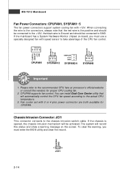
... to the chassis intrusion switch cable. CPUFAN supports fan control. the black wire is opened, the chassis intrusion mechanism will record this status and show a warning message on -board, you must use a specially designed fan with speed sensor to the actual CPU temperature. 3. Fan cooler set with +12V. To clear the warning, you must enter the BIOS utility and clear the record. MS-7512 Mainboard Fan Power Connectors: CPUFAN1, SYSFAN1~5 The fan power connectors support system cooling fan with 3 or 4 pins power connector are both...
... to the chassis intrusion switch cable. CPUFAN supports fan control. the black wire is opened, the chassis intrusion mechanism will record this status and show a warning message on -board, you must use a specially designed fan with speed sensor to the actual CPU temperature. 3. Fan cooler set with +12V. To clear the warning, you must enter the BIOS utility and clear the record. MS-7512 Mainboard Fan Power Connectors: CPUFAN1, SYSFAN1~5 The fan power connectors support system cooling fan with 3 or 4 pins power connector are both...

User Guide
Page 34
MS-7512 Mainboard Jumper The motherboard provides the following jumper for you power off the system before changing the jumpers 2. Overclocking may cause system instability or crash during boot, then please set to set the FSB. 1 JB2 JB1 1 3 1 3 1 3 1 3 1 3 Default 200->266 MHz 200->333 MHz 266->333 MHz 200->400 MHz 266->400 MHz 333->400 MHz Important 1. Follow the instructions below to change your motherboard's function through...
MS-7512 Mainboard Jumper The motherboard provides the following jumper for you power off the system before changing the jumpers 2. Overclocking may cause system instability or crash during boot, then please set to set the FSB. 1 JB2 JB1 1 3 1 3 1 3 1 3 1 3 Default 200->266 MHz 200->333 MHz 266->333 MHz 200->400 MHz 266->400 MHz 333->400 MHz Important 1. Follow the instructions below to change your motherboard's function through...
User Guide
Page 36
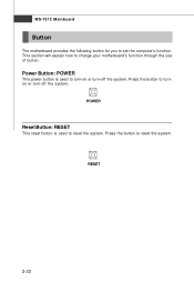
This section will explain how to reset the system. Press the button to turn-on or turn -off the system. RESET 2-22 POWER Reset Button: RESET This reset button is used to change your motherboard's function through the use of button. MS-7512 Mainboard Button The motherboard provides the following button for you to reset the system. Press the button to set the computer's function. Power Button: POWER This power button is used to turnon or turn -off the system.
This section will explain how to reset the system. Press the button to turn-on or turn -off the system. RESET 2-22 POWER Reset Button: RESET This reset button is used to change your motherboard's function through the use of button. MS-7512 Mainboard Button The motherboard provides the following button for you to reset the system. Press the button to set the computer's function. Power Button: POWER This power button is used to turnon or turn -off the system.
User Guide
Page 37
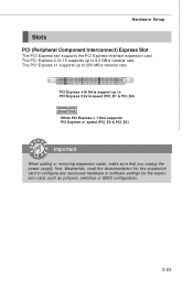
... transfer rate. PCI Express x16 Slots support up to PCI Express 2.0x16 speed (PCI_E1 & PCI_E4) White PCI Express x 1 Slot supports PCI Express x1 speed (PCI_E2 & PCI_E3) Important When adding or removing expansion cards, make sure that you unplug the power supply first. The PCI Express 2.0x 16 supports up to configure any necessary hardware or software settings for the expansion card, such as jumpers, switches or BIOS configuration. 2-23 Hardware Setup Slots PCI (Peripheral Component Interconnect) Express Slot The PCI Express slot supports the PCI Express interface expansion card.
... transfer rate. PCI Express x16 Slots support up to PCI Express 2.0x16 speed (PCI_E1 & PCI_E4) White PCI Express x 1 Slot supports PCI Express x1 speed (PCI_E2 & PCI_E3) Important When adding or removing expansion cards, make sure that you unplug the power supply first. The PCI Express 2.0x 16 supports up to configure any necessary hardware or software settings for the expansion card, such as jumpers, switches or BIOS configuration. 2-23 Hardware Setup Slots PCI (Peripheral Component Interconnect) Express Slot The PCI Express slot supports the PCI Express interface expansion card.

User Guide
Page 38
... expansion card to the PCI bus pins as jumpers, switches or BIOS configuration. MS-7512 Mainboard PCI (Peripheral Component Interconnect) Slot The PCI slot supports LAN card, SCSI card, USB card, and other add-on cards that comply with PCI specifications. 32-bit PCI Slot Important When adding or removing expansion cards, make sure that you unplug the power supply first. PCI Interrupt Request Routing The IRQ, acronym of interrupt request line and pronounced I-R-Q, are typically connected to configure any necessary hardware or software settings for...
... expansion card to the PCI bus pins as jumpers, switches or BIOS configuration. MS-7512 Mainboard PCI (Peripheral Component Interconnect) Slot The PCI slot supports LAN card, SCSI card, USB card, and other add-on cards that comply with PCI specifications. 32-bit PCI Slot Important When adding or removing expansion cards, make sure that you unplug the power supply first. PCI Interrupt Request Routing The IRQ, acronym of interrupt request line and pronounced I-R-Q, are typically connected to configure any necessary hardware or software settings for...

User Guide
Page 39
... utilize this section are installed on the CrossFire Edition graphics card will work. Please note that although you have to complete CrossFire: 1. b. The mainboard can auto detect the CrossFire mode by software, therefore you only need to connect a monitor to connect the golden fingers on the top of the same brand and specifications; Install the CrossFire Edition graphics card in the First mazarine PCIE x16 (PCI_E1) slot and install...
... utilize this section are installed on the CrossFire Edition graphics card will work. Please note that although you have to complete CrossFire: 1. b. The mainboard can auto detect the CrossFire mode by software, therefore you only need to connect a monitor to connect the golden fingers on the top of the same brand and specifications; Install the CrossFire Edition graphics card in the First mazarine PCIE x16 (PCI_E1) slot and install...
User Guide
Page 50
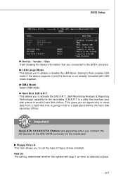
...-Monitoring Analysis & Reporting Technology) capability for the hard disks. Setting to Auto enables LBA mode if the device supports it and the devices is detected at boot. 3-7 This allows you connect the HD devices to the IDE/ SATA connector on the mainboard. Halt On The setting determines whether the system will showing the device information that you an opportunity to move data from a hard disk that monitors your disk status to set the type of floppy drives installed. BIOS Setup Device / Vender / Size...
...-Monitoring Analysis & Reporting Technology) capability for the hard disks. Setting to Auto enables LBA mode if the device supports it and the devices is detected at boot. 3-7 This allows you connect the HD devices to the IDE/ SATA connector on the mainboard. Halt On The setting determines whether the system will showing the device information that you an opportunity to move data from a hard disk that monitors your disk status to set the type of floppy drives installed. BIOS Setup Device / Vender / Size...
User Guide
Page 53
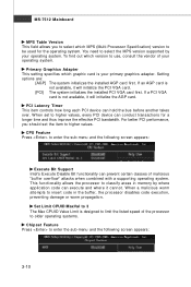
... initializes the installed AGP card first. CPU Feature Press to use, consult the vendor of malicious "buffer overflow" attacks when combined with a supporting operating system. For better PCI performance, you to select which MPS (Multi-Processor Specification) version to higher values. MS-7512 Mainboard MPS Table Version This field allows you should set to enter the sub-menu and the following screen appears: Execute Bit Support Intel's Execute Disable Bit functionality...
... initializes the installed AGP card first. CPU Feature Press to use, consult the vendor of malicious "buffer overflow" attacks when combined with a supporting operating system. For better PCI performance, you to select which MPS (Multi-Processor Specification) version to higher values. MS-7512 Mainboard MPS Table Version This field allows you should set to enter the sub-menu and the following screen appears: Execute Bit Support Intel's Execute Disable Bit functionality...
User Guide
Page 56
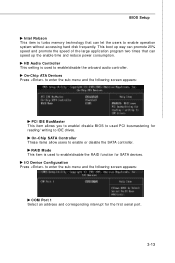
.../ writing to IDE drives. I/O Device Configuration Press to enter the sub-menu and the following screen appears: PCI IDE BusMaster This item allows you to enable/ disable BIOS to used PCI busmastering for the first serial port. 3-13 On-Chip SATA Controller These items allow users to enable or disable the SATA controller. RAID Mode This item is used to enable/disable the RAID function for SATA devices. HD Audio Controller This setting is used to enable/disable the onboard audio controller. This boot up the enable time and reduce power consumption. BIOS Setup Intel Robson...
.../ writing to IDE drives. I/O Device Configuration Press to enter the sub-menu and the following screen appears: PCI IDE BusMaster This item allows you to enable/ disable BIOS to used PCI busmastering for the first serial port. 3-13 On-Chip SATA Controller These items allow users to enable or disable the SATA controller. RAID Mode This item is used to enable/disable the RAID function for SATA devices. HD Audio Controller This setting is used to enable/disable the onboard audio controller. This boot up the enable time and reduce power consumption. BIOS Setup Intel Robson...
User Guide
Page 59
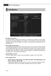
... FAN1/ SYS FAN2 Speed, CPU Vcore, 3.3V, 5V, 12V, 5V SB These items display the current status of all of recording the chassis intrusion status and issuing a warning message if the chassis is once opened. MS-7512 Mainboard H/W Monitor Chassis Intrusion The field enables or disables the feature of the monitored hardware devices/ components such as CPU voltage, temperatures and all fans' speeds. 3-16 It provides several sections to [Reset].
... FAN1/ SYS FAN2 Speed, CPU Vcore, 3.3V, 5V, 12V, 5V SB These items display the current status of all of recording the chassis intrusion status and issuing a warning message if the chassis is once opened. MS-7512 Mainboard H/W Monitor Chassis Intrusion The field enables or disables the feature of the monitored hardware devices/ components such as CPU voltage, temperatures and all fans' speeds. 3-16 It provides several sections to [Reset].
User Guide
Page 65
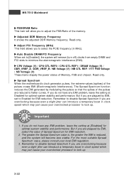
... DDR Memory frequency. Auto Disable DRAM /PCI Frequency W hen set to Enabled for EMI reduction. Spread Spectrum W hen the motherboard's clock generator pulses, the extreme values (spikes) of Memory, FSB and chipset. If you are overclocking because even a slight jitter can introduce a temporary boost in clock speed which may just cause your overclocked processor to disable Spread Spectrum if you do not have any EMI problem, leave the setting at Disabled for...
... DDR Memory frequency. Auto Disable DRAM /PCI Frequency W hen set to Enabled for EMI reduction. Spread Spectrum W hen the motherboard's clock generator pulses, the extreme values (spikes) of Memory, FSB and chipset. If you are overclocking because even a slight jitter can introduce a temporary boost in clock speed which may just cause your overclocked processor to disable Spread Spectrum if you do not have any EMI problem, leave the setting at Disabled for...
User Guide
Page 93
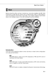
Dual Core Center Main Before using this utility. DOT Click DOT button to execute the function. VGA Click VGA button to read current CPU temperature, FSB and CPU clock of the MSI mainboard would be available. MB Click MB button to read current GPU temperature, GPU clock and memory clock of this utility, we have to install with the version 8.26 or newer driver)/ V046 or V060 graphics card can activate the full function of graphics card will show...
Dual Core Center Main Before using this utility. DOT Click DOT button to execute the function. VGA Click VGA button to read current CPU temperature, FSB and CPU clock of the MSI mainboard would be available. MB Click MB button to read current GPU temperature, GPU clock and memory clock of this utility, we have to install with the version 8.26 or newer driver)/ V046 or V060 graphics card can activate the full function of graphics card will show...
User Guide
Page 104
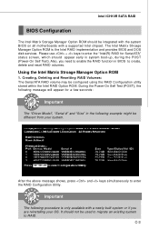
.... Creating, Deleting and Resetting RAID Volumes: The Serial ATA RAID volume may be used to migrate an existing system to RAID. Please use + keys to enter the "Intel(R) RAID for a few seconds: Important The "Driver Model", "Serial #" and "Size" in system boot-up, during the POST (Power-On Self Test). It should not be configured using the RAID Configuration utility stored within the Intel RAID Option ROM. During the Power-On Self Test (POST), the following message...
.... Creating, Deleting and Resetting RAID Volumes: The Serial ATA RAID volume may be used to migrate an existing system to RAID. Please use + keys to enter the "Intel(R) RAID for a few seconds: Important The "Driver Model", "Serial #" and "Size" in system boot-up, during the POST (Power-On Self Test). It should not be configured using the RAID Configuration utility stored within the Intel RAID Option ROM. During the Power-On Self Test (POST), the following message...
User Guide
Page 111
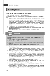
... SATA AHCI Controller(ICH8M-E)" or "Intel(R) 82801HBM SATA AHCI Controller(ICH8M)" when the system is formatted, and W indows setup starts copying files. W indows setup will need to continue. 9. Note: For W indows Vista you have successfully installed the Intel® Matrix Storage Manager driver, and W indows setup should confirm that you can use Floppy, CD/DVD or USB. Insert the MSI CD into the A: drive. Leave the disk in your system". MS-7512 Mainboard Installing Driver Install Driver in...
... SATA AHCI Controller(ICH8M-E)" or "Intel(R) 82801HBM SATA AHCI Controller(ICH8M)" when the system is formatted, and W indows setup starts copying files. W indows setup will need to continue. 9. Note: For W indows Vista you have successfully installed the Intel® Matrix Storage Manager driver, and W indows setup should confirm that you can use Floppy, CD/DVD or USB. Insert the MSI CD into the A: drive. Leave the disk in your system". MS-7512 Mainboard Installing Driver Install Driver in...
User Guide
Page 140
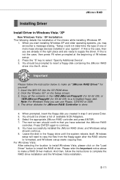
... MSI CD into the A: drive. JMicron RAID Installing Driver Install Driver in the floppy drive until the system reboots itself. You should be prompted to install the RAID driver. W hen you start installing Windows XP and older operating systems, you can use Floppy, CD/DVD or USB. 4. The driver diskette for 64-bit OS) to select "Specify Additional Device". 3. Select the appropriate JMicron RAID controller and press ENTER. 7. For W indows Vista: After selecting the location to install...
... MSI CD into the A: drive. JMicron RAID Installing Driver Install Driver in the floppy drive until the system reboots itself. You should be prompted to install the RAID driver. W hen you start installing Windows XP and older operating systems, you can use Floppy, CD/DVD or USB. 4. The driver diskette for 64-bit OS) to select "Specify Additional Device". 3. Select the appropriate JMicron RAID controller and press ENTER. 7. For W indows Vista: After selecting the location to install...


