User Manual
Page 12
... 42 CPU_PWR1~2, ATX_PWR1, PCIE_PWR1: Power Connectors 43 OC1: GAME BOOST Knob 44 JBLK_U1, JRATIO_U1: Base clock Plus, Ratio Plus connectors 45 OC_FS1: OC Force Enter BIOS Button 45 12 Contents
... 42 CPU_PWR1~2, ATX_PWR1, PCIE_PWR1: Power Connectors 43 OC1: GAME BOOST Knob 44 JBLK_U1, JRATIO_U1: Base clock Plus, Ratio Plus connectors 45 OC_FS1: OC Force Enter BIOS Button 45 12 Contents
User Manual
Page 13
...Connectors 49 JUSB5~6: USB 2.0 Connectors 50 POWER1, RESET1: Power Button, Reset Button 51 JBAT1: Clear CMOS (Reset BIOS) Jumper 51 JCI1: Chassis Intrusion Connector 52 BIOS_SW1: Multi-BIOS Switch 53 JRGB1, JRAINBOW1~2: RGB LED connectors 54 JCORSAIR1: CORSAIR Connector 55 DYNAMIC DASHBOARD 56 DYNAMIC DASHBOARD Status Table 56... Onboard LEDs ...57 EZ Debug LED...57 DIMM LEDs ...57 Fan LEDs...57 Multi-BIOS LEDs 58 XMP LED ...58 JPWRLED1: LED power input 58 CPU Power LED ...59 Debug Code LED 60 Hexadecimal Character Table 60 ...
...Connectors 49 JUSB5~6: USB 2.0 Connectors 50 POWER1, RESET1: Power Button, Reset Button 51 JBAT1: Clear CMOS (Reset BIOS) Jumper 51 JCI1: Chassis Intrusion Connector 52 BIOS_SW1: Multi-BIOS Switch 53 JRGB1, JRAINBOW1~2: RGB LED connectors 54 JCORSAIR1: CORSAIR Connector 55 DYNAMIC DASHBOARD 56 DYNAMIC DASHBOARD Status Table 56... Onboard LEDs ...57 EZ Debug LED...57 DIMM LEDs ...57 Fan LEDs...57 Multi-BIOS LEDs 58 XMP LED ...58 JPWRLED1: LED power input 58 CPU Power LED ...59 Debug Code LED 60 Hexadecimal Character Table 60 ...
User Manual
Page 14
Sound Tracker Tab 72 Settings Tab ...72 Killer Control Center 73 Configuring Bandwidth 73 BIOS Setup ...74 Entering BIOS Setup 74 Resetting BIOS...75 Updating BIOS...75 EZ Mode ...77 Advanced Mode ...79 SETTINGS...80 Advanced...80 Boot...86 Security ...87 Save & Exit...88 OC...89 M-FLASH ...95 OC PROFILE ...96 ...
Sound Tracker Tab 72 Settings Tab ...72 Killer Control Center 73 Configuring Bandwidth 73 BIOS Setup ...74 Entering BIOS Setup 74 Resetting BIOS...75 Updating BIOS...75 EZ Mode ...77 Advanced Mode ...79 SETTINGS...80 Advanced...80 Boot...86 Security ...87 Save & Exit...88 OC...89 M-FLASH ...95 OC PROFILE ...96 ...
User Manual
Page 15
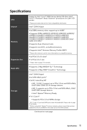
Intel® Z390 Chipset y 4x DDR4 memory slots, support up to PCIe 3.0 x4 and SATA 6Gb/s, 2242/ 2260/ 2280 storage devices ƒ...more compatibility information. Continued on compatible memory. y Supports 2-Way NVIDIA® SLI™ Technology y Supports 4-Way AMD® CrossFire™ Technology Intel® Z390 Chipset y 6x SATA 6Gb/s ports* y 3x M.2 slots (Key M)* ƒ M2_1 & M2_3 support up to PCIe 3.0 x4 and SATA 6Gb/s, 2242.... ** Before using Intel® Optane™ memory modules, please ensure that you have updated the drivers and BIOS to the latest version from MSI website.
Intel® Z390 Chipset y 4x DDR4 memory slots, support up to PCIe 3.0 x4 and SATA 6Gb/s, 2242/ 2260/ 2280 storage devices ƒ...more compatibility information. Continued on compatible memory. y Supports 2-Way NVIDIA® SLI™ Technology y Supports 4-Way AMD® CrossFire™ Technology Intel® Z390 Chipset y 6x SATA 6Gb/s ports* y 3x M.2 slots (Key M)* ƒ M2_1 & M2_3 support up to PCIe 3.0 x4 and SATA 6Gb/s, 2242.... ** Before using Intel® Optane™ memory modules, please ensure that you have updated the drivers and BIOS to the latest version from MSI website.

User Manual
Page 17
Continued from previous page Back Panel Connectors y 1x Flash BIOS Button y 1x Clear CMOS button y 2x Wi-Fi Antenna connectors y 1x PS/2 keyboard/ mouse combo port y 2x USB 3.1 Gen1 Type-A ports y 2x LAN (RJ45) ports y ...
Continued from previous page Back Panel Connectors y 1x Flash BIOS Button y 1x Clear CMOS button y 2x Wi-Fi Antenna connectors y 1x PS/2 keyboard/ mouse combo port y 2x USB 3.1 Gen1 Type-A ports y 2x LAN (RJ45) ports y ...

User Manual
Page 18
...LED Display Panel I/O Controller y 1x GAME BOOST knob y 1x OC retry button y 1x OC force enter BIOS button y 1x Power button y 1x Reset button y 1x JBLK_U1 pinheader y 1x JRATIO_U1 pinheader y 1x Multi-BIOS switch y 1x PCIe CeaseFire switch y 1x Slow mode jumper y 1x 2-Digit Debug Code LED y 4x ...detection y CPU/System fan speed detection y CPU/System fan speed control Form Factor y E-ATX Form Factor y 12 in . (30.5 cm x 27.2 cm) BIOS Features y Dual BIOS y 2x 128 Mb flash y UEFI AMI BIOS y ACPI 6.1, SMBIOS 2.8 y Multi-language Continued on next page 18 Specifications x 10.7 in .
...LED Display Panel I/O Controller y 1x GAME BOOST knob y 1x OC retry button y 1x OC force enter BIOS button y 1x Power button y 1x Reset button y 1x JBLK_U1 pinheader y 1x JRATIO_U1 pinheader y 1x Multi-BIOS switch y 1x PCIe CeaseFire switch y 1x Slow mode jumper y 1x 2-Digit Debug Code LED y 4x ...detection y CPU/System fan speed detection y CPU/System fan speed control Form Factor y E-ATX Form Factor y 12 in . (30.5 cm x 27.2 cm) BIOS Features y Dual BIOS y 2x 128 Mb flash y UEFI AMI BIOS y ACPI 6.1, SMBIOS 2.8 y Multi-language Continued on next page 18 Specifications x 10.7 in .

User Manual
Page 21
Special Features Continued from previous page y VR ƒ VR Ready ƒ Gamer Experience ƒ GAMING HOTKEY ƒ GAMING MOUSE Control y BIOS ƒ Click BIOS 5 ƒ Flash BIOS Button ƒ Dual BIOS y Certification ƒ Quadro SLI Ready ƒ Quadro Ready ƒ GAMING Certified JCORSAIR1 Connector Specification Supporting CORSAIR RGB Products Lighting Node PRO LED Strip HD120 RGB Fan SP120 RGB Fan LL120 RGB Fan Maximum connection 20* * 20% brightness is recommended when the number of LED strips exceeds 8. 6 6 6 Specifications 21
Special Features Continued from previous page y VR ƒ VR Ready ƒ Gamer Experience ƒ GAMING HOTKEY ƒ GAMING MOUSE Control y BIOS ƒ Click BIOS 5 ƒ Flash BIOS Button ƒ Dual BIOS y Certification ƒ Quadro SLI Ready ƒ Quadro Ready ƒ GAMING Certified JCORSAIR1 Connector Specification Supporting CORSAIR RGB Products Lighting Node PRO LED Strip HD120 RGB Fan SP120 RGB Fan LL120 RGB Fan Maximum connection 20* * 20% brightness is recommended when the number of LED strips exceeds 8. 6 6 6 Specifications 21

User Manual
Page 24
... CMOS PS/2 LAN LAN USB 3.1 Gen2 Audio Ports USB 3.1 Gen1 Flash BIOS Button USB 3.1 Gen2/ Flash BIOS Port Optical S/PDIF-Out 6.3mm headphone port USB 3.1 Gen2 Type-C y Clear CMOS button - y Flash BIOS Button/ Port - This port is used for Updating BIOS with Flash BIOS Button. Press and hold the Clear CMOS button for about 5-10...
... CMOS PS/2 LAN LAN USB 3.1 Gen2 Audio Ports USB 3.1 Gen1 Flash BIOS Button USB 3.1 Gen2/ Flash BIOS Port Optical S/PDIF-Out 6.3mm headphone port USB 3.1 Gen2 Type-C y Clear CMOS button - y Flash BIOS Button/ Port - This port is used for Updating BIOS with Flash BIOS Button. Press and hold the Clear CMOS button for about 5-10...
User Manual
Page 31
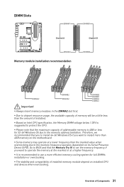
... overclocking. Therefore, we recommended that the maximum capacity of installed. y Due to install more efficient memory cooling system for 32-bit Windows OS due to BIOS and find the Memory Try It! Overview of installed memory module depend on the motherboard. Go to the memory address limitation. y The stability and compatibility...
... overclocking. Therefore, we recommended that the maximum capacity of installed. y Due to install more efficient memory cooling system for 32-bit Windows OS due to BIOS and find the Memory Try It! Overview of installed memory module depend on the motherboard. Go to the memory address limitation. y The stability and compatibility...
User Manual
Page 44
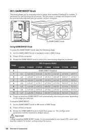
...) for better cooling and performance. 44 Overview of Components Important y When enabling GAME BOOST mode, it is recommended to HW mode in BIOS Setup. 2. The processor's voltage and frequency will be automatically adjusted after you selected. Set the GAME BOOST knob to use liquid CPU cooler... with dual fan radiator for overclocking the processor. Power off the computer. 3. Rotate the GAME BOOST knob to hardware mode in BIOS Setup. 2. OC1: GAME BOOST Knob This knob allows you desire. Power on and then GAME BOOST will automatically overclock processor depending on ....
...) for better cooling and performance. 44 Overview of Components Important y When enabling GAME BOOST mode, it is recommended to HW mode in BIOS Setup. 2. The processor's voltage and frequency will be automatically adjusted after you selected. Set the GAME BOOST knob to use liquid CPU cooler... with dual fan radiator for overclocking the processor. Power off the computer. 3. Rotate the GAME BOOST knob to hardware mode in BIOS Setup. 2. OC1: GAME BOOST Knob This knob allows you desire. Power on and then GAME BOOST will automatically overclock processor depending on ....

User Manual
Page 45
...depends on the components of Components 45 JBLK_U1, JRATIO_U1: Base clock Plus, Ratio Plus connectors You can also control the GAME BOOST function in the BIOS > OC menu unchanged. JBLK_U1 (Short the jumper to increase the CPU base clock) JRATIO_U1 (Short the jumper to increase the CPU ratio) OC_FS1:... showing the OC_FAIL message. OC_RT2: OC Retry Button When you activate the GAME BOOST function, please leave the settings in BIOS Setup or with MSI DRAGON CENTER software. Press the button connecting to JBLK_U1 to increase the CPU base clock or press the button connecting to JRATIO_U1 to ...
...depends on the components of Components 45 JBLK_U1, JRATIO_U1: Base clock Plus, Ratio Plus connectors You can also control the GAME BOOST function in the BIOS > OC menu unchanged. JBLK_U1 (Short the jumper to increase the CPU base clock) JRATIO_U1 (Short the jumper to increase the CPU ratio) OC_FS1:... showing the OC_FAIL message. OC_RT2: OC Retry Button When you activate the GAME BOOST function, please leave the settings in BIOS Setup or with MSI DRAGON CENTER software. Press the button connecting to JBLK_U1 to increase the CPU base clock or press the button connecting to JRATIO_U1 to ...

User Manual
Page 46
... used for LN2 cooling solution, that provides the extreme overclocking conditions, to boot at their own risks. Normal (default) Enabled (Please enable this jumper during BIOS POST.) Important y Users will vary according to the CPU version. y The overclocking results will try extreme low temperature (must be started. 46 Overview of the...
... used for LN2 cooling solution, that provides the extreme overclocking conditions, to boot at their own risks. Normal (default) Enabled (Please enable this jumper during BIOS POST.) Important y Users will vary according to the CPU version. y The overclocking results will try extreme low temperature (must be started. 46 Overview of the...
User Manual
Page 47
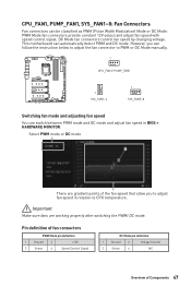
... mode and adjusting fan speed You can switch between PWM mode and DC mode and adjust fan speed in relation to adjust fan speed in BIOS > HARDWARE MONITOR. CPU_FAN1, PUMP_FAN1, SYS_FAN1~8: Fan Connectors Fan connectors can automatically detect PWM and DC mode. Select PWM mode or DC mode There are working...
... mode and adjusting fan speed You can switch between PWM mode and DC mode and adjust fan speed in relation to adjust fan speed in BIOS > HARDWARE MONITOR. CPU_FAN1, PUMP_FAN1, SYS_FAN1~8: Fan Connectors Fan connectors can automatically detect PWM and DC mode. Select PWM mode or DC mode There are working...
User Manual
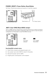
Page 51
... the computer and unplug the power cord 2. Plug the power cord and power on / reset the computer. Reset button Power button JBAT1: Clear CMOS (Reset BIOS) Jumper There is CMOS memory onboard that is external powered from JBAT1. 4. Keep Data (default) Clear CMOS/ Reset...
... the computer and unplug the power cord 2. Plug the power cord and power on / reset the computer. Reset button Power button JBAT1: Clear CMOS (Reset BIOS) Jumper There is CMOS memory onboard that is external powered from JBAT1. 4. Keep Data (default) Clear CMOS/ Reset...

User Manual
Page 52
...Yes. 6. Press F10 to save and exit and then press the Enter key to the chassis intrusion switch/ sensor on . Set Chassis Intrusion to BIOS > SETTINGS > Security > Chassis Intrusion Configuration. 4. Once the chassis cover is opened again, a warning message will be displayed on screen when the... computer is turned on the chassis. 2. Press F10 to save and exit and then press the Enter key to BIOS > SETTINGS > Security > Chassis Intrusion Configuration. 2. Go to Enabled. 5. Go to select Yes. 52 Overview of Components Close the chassis cover. 3. ...
...Yes. 6. Press F10 to save and exit and then press the Enter key to the chassis intrusion switch/ sensor on . Set Chassis Intrusion to BIOS > SETTINGS > Security > Chassis Intrusion Configuration. 4. Once the chassis cover is opened again, a warning message will be displayed on screen when the... computer is turned on the chassis. 2. Press F10 to save and exit and then press the Enter key to BIOS > SETTINGS > Security > Chassis Intrusion Configuration. 2. Go to Enabled. 5. Go to select Yes. 52 Overview of Components Close the chassis cover. 3. ...
User Manual
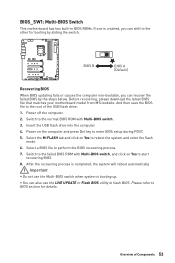
Page 53
... Yes to reboot the system and enter the flash mode. 6. Before recovering, please download the latest BIOS file that matches your motherboard model from MSI website. Switch to flash BIOS. After the recovering process is completed, the system will reboot automatically Important y Do not use the... LIVE UPDATE or Flash BIOS utility to the failed BIOS ROM with Multi-BIOS switch. 3. y You can also use the Multi-BIOS switch when system...
... Yes to reboot the system and enter the flash mode. 6. Before recovering, please download the latest BIOS file that matches your motherboard model from MSI website. Switch to flash BIOS. After the recovering process is completed, the system will reboot automatically Important y Do not use the... LIVE UPDATE or Flash BIOS utility to the failed BIOS ROM with Multi-BIOS switch. 3. y You can also use the Multi-BIOS switch when system...

User Manual
Page 56
... S4/S5 (Suspend to Disk/ Shutdown) User profile 256*64px .gif Flash BIOS (Update) Important For information on configuration and customization DYNAMIC DASHBOARD, please refer to the MSI's website. 56 Overview of Components You can be used to display system information, CPU temperature..., CPU speed, BIOS flash status and error message. DYNAMIC DASHBOARD The DYNAMIC DASHBOARD can use MSI's software to configure and customize the...
... S4/S5 (Suspend to Disk/ Shutdown) User profile 256*64px .gif Flash BIOS (Update) Important For information on configuration and customization DYNAMIC DASHBOARD, please refer to the MSI's website. 56 Overview of Components You can be used to display system information, CPU temperature..., CPU speed, BIOS flash status and error message. DYNAMIC DASHBOARD The DYNAMIC DASHBOARD can use MSI's software to configure and customize the...

User Manual
Page 58
Multi-BIOS LEDs Multi-BIOS LEDs indicate which BIOS ROM is used by retailers to demonstrate onboard LED light effects. XMP LED JPWRLED1: LED power input This connector is in operation. LED power input 58 Onboard LEDs BIOS B LED (White) BIOS A LED (Red) XMP LED This LED indicates the XMP (Extreme Memory Profile) mode is enabled. JPWRLED1 -
Multi-BIOS LEDs Multi-BIOS LEDs indicate which BIOS ROM is used by retailers to demonstrate onboard LED light effects. XMP LED JPWRLED1: LED power input This connector is in operation. LED power input 58 Onboard LEDs BIOS B LED (White) BIOS A LED (Red) XMP LED This LED indicates the XMP (Extreme Memory Profile) mode is enabled. JPWRLED1 -

User Manual
Page 74
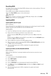
...to enter BIOS setup. y In MSI Dragon Center application, click on the screen during the boot process. Entering BIOS Setup Please refer the following methods to the HELP information panel for BIOS item description. Important y BIOS items are familiar with BIOS. The system will reboot and enter BIOS setup directly...F9: Save Overclocking Profile F10: Save Change and Reset* F12: Take a screenshot and save it provides the modification information. BIOS Setup The default settings offer the optimal performance for system stability in this chapter are for reference only and may be slightly ...
...to enter BIOS setup. y In MSI Dragon Center application, click on the screen during the boot process. Entering BIOS Setup Please refer the following methods to the HELP information panel for BIOS item description. Important y BIOS items are familiar with BIOS. The system will reboot and enter BIOS setup directly...F9: Save Overclocking Profile F10: Save Change and Reset* F12: Take a screenshot and save it provides the modification information. BIOS Setup The default settings offer the optimal performance for system stability in this chapter are for reference only and may be slightly ...
User Manual
Page 75
...to the Clear CMOS jumper section for resetting BIOS. y Short the Clear CMOS jumper on Yes to the target BIOS ROM with Multi-BIOS switch, and click on the motherboard. Click Next and choose In Windows mode. Updating BIOS Updating BIOS with MSI DRAGON CENTER Before updating: Make sure the... LAN driver is already installed and the Internet connection is off before clearing CMOS data. When prompted, switch to start updating BIOS. 6. Insert the USB flash drive that ...
...to the Clear CMOS jumper section for resetting BIOS. y Short the Clear CMOS jumper on Yes to the target BIOS ROM with Multi-BIOS switch, and click on the motherboard. Click Next and choose In Windows mode. Updating BIOS Updating BIOS with MSI DRAGON CENTER Before updating: Make sure the... LAN driver is already installed and the Internet connection is off before clearing CMOS data. When prompted, switch to start updating BIOS. 6. Insert the USB flash drive that ...


