User Manual
Page 12
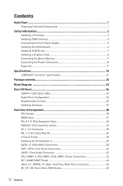
...a Processor 3 Installing DDR4 memory 4 Connecting the Front Panel Header 5 Installing the Motherboard 6 Installing SATA Drives 7 Installing a Graphics Card 8 Connecting Peripheral Devices 9 Connecting the Power Connectors 10 Power On...11 Specifications...15 JCORSAIR1 Connector Specification 21 Package contents 22 Block Diagram ...23 Rear I/O Panel...24 LAN Port LED Status Table 24 Audio Ports Configuration 24 Realtek Audio Console 25 Installing Antennas 27 Overview of Components 28 CPU Socket ...30 DIMM Slots...31 PCI_E1~5: PCIe Expansion Slots 32 PEGSW1: PCIe CeaseFire Switch...
...a Processor 3 Installing DDR4 memory 4 Connecting the Front Panel Header 5 Installing the Motherboard 6 Installing SATA Drives 7 Installing a Graphics Card 8 Connecting Peripheral Devices 9 Connecting the Power Connectors 10 Power On...11 Specifications...15 JCORSAIR1 Connector Specification 21 Package contents 22 Block Diagram ...23 Rear I/O Panel...24 LAN Port LED Status Table 24 Audio Ports Configuration 24 Realtek Audio Console 25 Installing Antennas 27 Overview of Components 28 CPU Socket ...30 DIMM Slots...31 PCI_E1~5: PCIe Expansion Slots 32 PEGSW1: PCIe CeaseFire Switch...
User Manual
Page 13
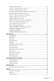
... Status Table 56 Onboard LEDs ...57 EZ Debug LED...57 DIMM LEDs ...57 Fan LEDs...57 Multi-BIOS LEDs 58 XMP LED ...58 JPWRLED1: LED power input 58 CPU Power LED ...59 Debug Code LED 60 Hexadecimal Character Table 60 Boot Phases...60 Debug Code LED Table 60 ACPI States Codes 65 CPU Temperature 65 Installing OS, Drivers & Utilities 66 Installing Windows® 10 66 Installing Drivers 66 Installing Utilities 66 MYSTIC LIGHT...67 Device LED effect control screen 67 Nahimic 3 ...70 Installation and Update 70 Audio Tab ...70 Microphone...
... Status Table 56 Onboard LEDs ...57 EZ Debug LED...57 DIMM LEDs ...57 Fan LEDs...57 Multi-BIOS LEDs 58 XMP LED ...58 JPWRLED1: LED power input 58 CPU Power LED ...59 Debug Code LED 60 Hexadecimal Character Table 60 Boot Phases...60 Debug Code LED Table 60 ACPI States Codes 65 CPU Temperature 65 Installing OS, Drivers & Utilities 66 Installing Windows® 10 66 Installing Drivers 66 Installing Utilities 66 MYSTIC LIGHT...67 Device LED effect control screen 67 Nahimic 3 ...70 Installation and Update 70 Audio Tab ...70 Microphone...
User Manual
Page 61
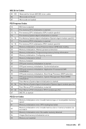
... Processor (BSP) selection CPU post-memory initialization. No usable memory detected 54 Unspecified memory initialization error 55 Memory not installed Onboard LEDs 61 Cache initialization CPU post-memory initialization. SPD reading has failed 52 Memory initialization error. Invalid memory size or memory modules do not match 53 Memory initialization error. Memory presence detection Memory initialization. System Management Mode (SMM) initialization Post-Memory System Agent initialization is started Post-Memory System Agent initialization (System Agent module specific...
... Processor (BSP) selection CPU post-memory initialization. No usable memory detected 54 Unspecified memory initialization error 55 Memory not installed Onboard LEDs 61 Cache initialization CPU post-memory initialization. SPD reading has failed 52 Memory initialization error. Invalid memory size or memory modules do not match 53 Memory initialization error. Memory presence detection Memory initialization. System Management Mode (SMM) initialization Post-Memory System Agent initialization is started Post-Memory System Agent initialization (System Agent module specific...
User Manual
Page 62
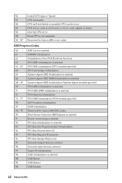
... is started PCH DXE SMM initialization is started PCH devices initialization PCH DXE Initialization (PCH module specific) ACPI module initialization CSM initialization Reserved for future AMI DXE codes Boot Device Selection (BDS) phase is started Driver connecting is started PCI Bus initialization is started PCI Bus Hot Plug Controller Initialization PCI Bus Enumeration 32 PCI Bus Request Resources PCI Bus Assign Resources Console Output devices connect Console input devices connect Super IO Initialization USB initialization is started USB Reset USB Detect USB Enable 62 Onboard LEDs
... is started PCH DXE SMM initialization is started PCH devices initialization PCH DXE Initialization (PCH module specific) ACPI module initialization CSM initialization Reserved for future AMI DXE codes Boot Device Selection (BDS) phase is started Driver connecting is started PCI Bus initialization is started PCI Bus Hot Plug Controller Initialization PCI Bus Enumeration 32 PCI Bus Request Resources PCI Bus Assign Resources Console Output devices connect Console input devices connect Super IO Initialization USB initialization is started USB Reset USB Detect USB Enable 62 Onboard LEDs
User Manual
Page 63
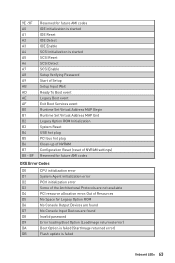
... Enable Setup Verifying Password Start of Setup Setup Input Wait Ready To Boot event Legacy Boot event Exit Boot Services event Runtime Set Virtual Address MAP Begin Runtime Set Virtual Address MAP End Legacy Option ROM Initialization System Reset USB hot plug PCI bus hot plug Clean-up of NVRAM Configuration Reset (reset of the Architectural Protocols are found D7 No Console Input Devices are not available D4 PCI resource allocation error. BF Reserved for future AMI codes IDE initialization is started IDE Reset IDE Detect IDE Enable...
... Enable Setup Verifying Password Start of Setup Setup Input Wait Ready To Boot event Legacy Boot event Exit Boot Services event Runtime Set Virtual Address MAP Begin Runtime Set Virtual Address MAP End Legacy Option ROM Initialization System Reset USB hot plug PCI bus hot plug Clean-up of NVRAM Configuration Reset (reset of the Architectural Protocols are found D7 No Console Input Devices are not available D4 PCI resource allocation error. BF Reserved for future AMI codes IDE initialization is started IDE Reset IDE Detect IDE Enable...
User Manual
Page 66
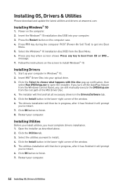
... Install button in the Drivers/Software tab. 5. The utilities installation will then be in the lower-right corner of the window. 5. Select the Windows® 10 installation disc/USB from CD or DVD... Press any key when screen shows Press any key to boot from the Boot Menu. 6. Click the Utilities tab. 3. Press F11 key during the computer POST (Power-On Self Test) to restart. 6. Restart your optical drive. 3. Click OK button to install...
... Install button in the Drivers/Software tab. 5. The utilities installation will then be in the lower-right corner of the window. 5. Select the Windows® 10 installation disc/USB from CD or DVD... Press any key when screen shows Press any key to boot from the Boot Menu. 6. Click the Utilities tab. 3. Press F11 key during the computer POST (Power-On Self Test) to restart. 6. Restart your optical drive. 3. Click OK button to install...
User Manual
Page 70
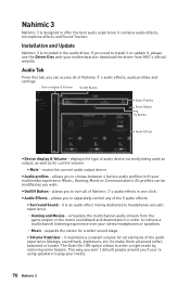
... between 4 factory audio profiles to fit your motherboard or download the driver from MSI's official website. Installation and Update Nahimic 3 is included in one click. mutes the current audio output device. allows you to separately control any of Nahimic 3's audio effects, audio profiles and settings. The Quiet On / Off option allows to make them all sound softer, balanced or louder. y Audio profiles - virtualizes the multichannel audio stream from...
... between 4 factory audio profiles to fit your motherboard or download the driver from MSI's official website. Installation and Update Nahimic 3 is included in one click. mutes the current audio output device. allows you to separately control any of Nahimic 3's audio effects, audio profiles and settings. The Quiet On / Off option allows to make them all sound softer, balanced or louder. y Audio profiles - virtualizes the multichannel audio stream from...
User Manual
Page 75
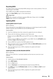
... M-FLASH button and click on Download icon to reboot the system. 3. When prompted, switch to start updating BIOS. 6. Click Next and choose In Windows mode. BIOS Setup 75 y Short the Clear CMOS jumper on Yes to the target BIOS ROM with Multi-BIOS switch, and click on the motherboard. Insert the USB flash drive that matches your motherboard model from MSI website. Updating the BIOS with M-FLASH Before updating: Please download the latest BIOS file that contains the update file into the USB flash drive. Select a BIOS file to start recovering BIOS. 5. Install...
... M-FLASH button and click on Download icon to reboot the system. 3. When prompted, switch to start updating BIOS. 6. Click Next and choose In Windows mode. BIOS Setup 75 y Short the Clear CMOS jumper on Yes to the target BIOS ROM with Multi-BIOS switch, and click on the motherboard. Insert the USB flash drive that matches your motherboard model from MSI website. Updating the BIOS with M-FLASH Before updating: Please download the latest BIOS file that contains the update file into the USB flash drive. Select a BIOS file to start recovering BIOS. 5. Install...
User Manual
Page 77
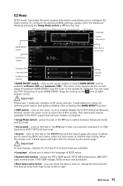
... - shows the CPU/ DDR speed, CPU/ MB temperature, MB/ CPU type, memory size, CPU/ DDR voltage, BIOS version and build date. The boot priority from high to low is installed. To configure the advanced BIOS settings, please enter the Advanced Mode by BIOS item name, enter the item name to right. y Setup Mode switch - It allows you to enable/ disable the X.M.P. (Extreme Memory Profile). Move the mouse over a blank space and right click the mouse to switch between software (SW...
... - shows the CPU/ DDR speed, CPU/ MB temperature, MB/ CPU type, memory size, CPU/ DDR voltage, BIOS version and build date. The boot priority from high to low is installed. To configure the advanced BIOS settings, please enter the Advanced Mode by BIOS item name, enter the item name to right. y Setup Mode switch - It allows you to enable/ disable the X.M.P. (Extreme Memory Profile). Move the mouse over a blank space and right click the mouse to switch between software (SW...
User Manual
Page 78
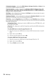
... page. 2. enable or disable the LAN Option ROM, M.2/Optane Genie, HD audio controller, AHCI, RAID, CPU Fan Fail Warning Control and BIOS Log Review by percentage. y Function buttons - It allows you to add the frequently-used/ favorite BIOS setting items in one page. ƒ To add a BIOS item to update BIOS with a USB flash drive. allows you to create personal BIOS menu where you to enter Favorites menu. Move the mouse over a BIOS item on this button to display the M-Flash menu that...
... page. 2. enable or disable the LAN Option ROM, M.2/Optane Genie, HD audio controller, AHCI, RAID, CPU Fan Fail Warning Control and BIOS Log Review by percentage. y Function buttons - It allows you to add the frequently-used/ favorite BIOS setting items in one page. ƒ To add a BIOS item to update BIOS with a USB flash drive. allows you to create personal BIOS menu where you to enter Favorites menu. Move the mouse over a BIOS item on this button to display the M-Flash menu that...
User Manual
Page 81
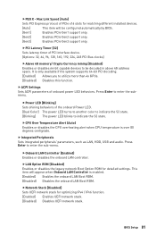
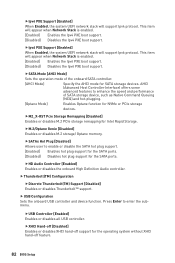
... PCIe Gen3 support only. fLAN Option ROM [Disabled] Enables or disables the legacy network Boot Option ROM for optimizing IPv4 / IPv6 function. [Enabled] Enables UEFI network stack. [Disabled] Disables UEFI network stack. fNetwork Stack [Disabled] Sets UEFI network stack for detailed settings. fPCI Latency Timer [32] Sets latency timer of the onboard Power LED. [Dual Color] The power LED turns to another color to indicate the S3 state. [Blinking] The power LED blinks to utilize more than 4x GPUs. [Disabled] Disables this function. Press Enter to enter the sub-menu. BIOS Setup...
... PCIe Gen3 support only. fLAN Option ROM [Disabled] Enables or disables the legacy network Boot Option ROM for optimizing IPv4 / IPv6 function. [Enabled] Enables UEFI network stack. [Disabled] Disables UEFI network stack. fNetwork Stack [Disabled] Sets UEFI network stack for detailed settings. fPCI Latency Timer [32] Sets latency timer of the onboard Power LED. [Dual Color] The power LED turns to another color to indicate the S3 state. [Blinking] The power LED blinks to utilize more than 4x GPUs. [Disabled] Disables this function. Press Enter to enter the sub-menu. BIOS Setup...
User Manual
Page 82
...when Network Stack is enabled. [Enabled] Enables the Ipv6 PXE boot support. [Disabled] Disables the Ipv6 PXE boot support. fM2_X-RST Pcie Storage Remapping [Disabled] Enables or disables M.2 PCIe storage remapping for the operating system without XHCI hand-off support for Intel Rapid Storage. fUSB Controller [Enabled] Enables or disables all USB controller. fSATAx Hot Plug [Disabled] Allows user to enter the submenu. f USB Configuration Sets the onboard USB controller and device function. fSATA Mode [AHCI Mode] Sets the operation mode of SATA storage device, such...
...when Network Stack is enabled. [Enabled] Enables the Ipv6 PXE boot support. [Disabled] Disables the Ipv6 PXE boot support. fM2_X-RST Pcie Storage Remapping [Disabled] Enables or disables M.2 PCIe storage remapping for the operating system without XHCI hand-off support for Intel Rapid Storage. fUSB Controller [Enabled] Enables or disables all USB controller. fSATAx Hot Plug [Disabled] Allows user to enter the submenu. f USB Configuration Sets the onboard USB controller and device function. fSATA Mode [AHCI Mode] Sets the operation mode of SATA storage device, such...
User Manual
Page 83
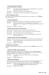
... installed devices & utilities (hardware & software) should meet the Windows 10 requirements. [Enabled] The system will switch to UEFI mode to enter the sub-menu. fLegacy USB Support [Enabled] Sets Legacy USB function support. [Auto] The system will automatically detect if any USB device is connected and enable the legacy USB support. [Enabled] Enable the USB support under legacy mode. fSystem Power Fault Protection [Disabled] Enables or disables the system to speed up system boot time which is faster than the boot time of ErP and AC Power Loss behaviors. f Power Management Setup...
... installed devices & utilities (hardware & software) should meet the Windows 10 requirements. [Enabled] The system will switch to UEFI mode to enter the sub-menu. fLegacy USB Support [Enabled] Sets Legacy USB function support. [Auto] The system will automatically detect if any USB device is connected and enable the legacy USB support. [Enabled] Enable the USB support under legacy mode. fSystem Power Fault Protection [Disabled] Enables or disables the system to speed up system boot time which is faster than the boot time of ErP and AC Power Loss behaviors. f Power Management Setup...
User Manual
Page 85
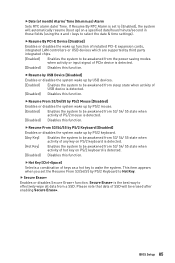
.../2 Mouse [Disabled] Enables or disables the system wake up function of installed PCI-E expansion cards, integrated LAN controllers or USB devices which are supported by PS/2 Keyboard to effectively wipe all data from the power saving modes when activity or input signal of hot key on a specified date/hour/minute/second in these fields (using the + and - This item appears when you set to be...
.../2 Mouse [Disabled] Enables or disables the system wake up function of installed PCI-E expansion cards, integrated LAN controllers or USB devices which are supported by PS/2 Keyboard to effectively wipe all data from the power saving modes when activity or input signal of hot key on a specified date/hour/minute/second in these fields (using the + and - This item appears when you set to be...
User Manual
Page 90
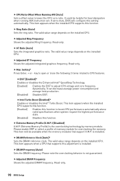
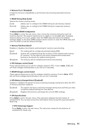
... installed CPU. fEIST [Enabled]* Enables or disables the Enhanced Intel® SpeedStep Technology. [Enabled] Enables the EIST to lower the CPU core ratio. f DRAM Reference Clock [Auto]* Sets the DRAM reference clock. f Adjusted GT Frequency Shows the adjusted integrated graphics frequency. Read-only. 90 BIOS Setup f GT Ratio [Auto] Sets the integrated graphics ratio. Read-only. key to open or close the following 3 items related to Auto, BIOS will be helpful for overclocking the memory. It can decrease average power...
... installed CPU. fEIST [Enabled]* Enables or disables the Enhanced Intel® SpeedStep Technology. [Enabled] Enables the EIST to lower the CPU core ratio. f DRAM Reference Clock [Auto]* Sets the DRAM reference clock. f Adjusted GT Frequency Shows the adjusted integrated graphics frequency. Read-only. 90 BIOS Setup f GT Ratio [Auto] Sets the integrated graphics ratio. Read-only. key to open or close the following 3 items related to Auto, BIOS will be helpful for overclocking the memory. It can decrease average power...
User Manual
Page 91
... load the default settings for memory. Disables this information menu at any time by choosing optimized memory preset. Read only. If it manually. f DRAM Voltages control [Auto] These options allows you can also access this function and keeps the current BIOS settings. This sub-menu displays the information of installed CPU. The sub-menu shows the key features of installed CPU. f DRAM Timing Mode [Link] Selects the memory timing mode. [Link] Allows user to configure the DRAM timing for memory every booting. [Auto] [Enabled] [Disabled] The setting...
... load the default settings for memory. Disables this information menu at any time by choosing optimized memory preset. Read only. If it manually. f DRAM Voltages control [Auto] These options allows you can also access this function and keeps the current BIOS settings. This sub-menu displays the information of installed CPU. The sub-menu shows the key features of installed CPU. f DRAM Timing Mode [Link] Selects the memory timing mode. [Link] Allows user to configure the DRAM timing for memory every booting. [Auto] [Enabled] [Disabled] The setting...
User Manual
Page 93
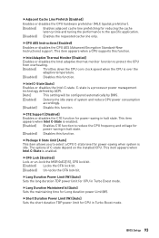
... the CPU core clock speed when the CPU is a processor power management technology defined by ACPI. [Auto] This setting will be configured automatically by BIOS. [Enabled] Detects the idle state of C-state depend on the installed CPU. fLong Duration Power Limit (W) [Auto] Sets the long duration TDP power limit for Long duration power Limit(W). fCPU AES Instructions [Enabled] Enables or disables the CPU AES (Advanced Encryption Standard-New Instructions) support. C-state is over the adaptive temperature. [Disabled] Disables...
... the CPU core clock speed when the CPU is a processor power management technology defined by ACPI. [Auto] This setting will be configured automatically by BIOS. [Enabled] Detects the idle state of C-state depend on the installed CPU. fLong Duration Power Limit (W) [Auto] Sets the long duration TDP power limit for Long duration power Limit(W). fCPU AES Instructions [Enabled] Enables or disables the CPU AES (Advanced Encryption Standard-New Instructions) support. C-state is over the adaptive temperature. [Disabled] Disables...
User Manual
Page 103
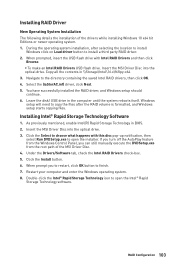
... in BIOS. 2. You have successfully installed the RAID driver, and Windows setup should continue. 6. If you turn off the AutoPlay feature from the Windows Control Panel, you to restart, click OK button to install a third party RAID driver. 2. Restart your computer and enter the Windows operating system. 8. Windows setup will need to the directory containing the saved Intel RAID drivers, then click OK. 4. As previously mentioned, enable Intel(R) Rapid Storage Technology in \\Storage\Intel...
... in BIOS. 2. You have successfully installed the RAID driver, and Windows setup should continue. 6. If you turn off the AutoPlay feature from the Windows Control Panel, you to restart, click OK button to install a third party RAID driver. 2. Restart your computer and enter the Windows operating system. 8. Windows setup will need to the directory containing the saved Intel RAID drivers, then click OK. 4. As previously mentioned, enable Intel(R) Rapid Storage Technology in \\Storage\Intel...
User Manual
Page 104
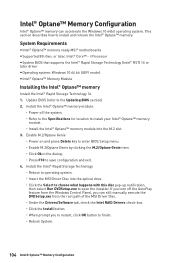
... install and remove the Intel® Optane™ memory. System Requirements y Intel® Optane™ memory ready MSI® motherboards y Supported 8th Gen, or later, Intel® Core™ - i Processor y System BIOS that supports the Intel® Rapid Storage Technology (Intel® RST) 16 or later driver y Operating system: Windows 10 64 bit (UEFI mode). Install the Intel® Optane™ memory module. ˜ Power off the AutoPlay feature from the Windows Control Panel...
... install and remove the Intel® Optane™ memory. System Requirements y Intel® Optane™ memory ready MSI® motherboards y Supported 8th Gen, or later, Intel® Core™ - i Processor y System BIOS that supports the Intel® Rapid Storage Technology (Intel® RST) 16 or later driver y Operating system: Windows 10 64 bit (UEFI mode). Install the Intel® Optane™ memory module. ˜ Power off the AutoPlay feature from the Windows Control Panel...
User Manual
Page 107
... power is turned on the motherboard rear IO panel. y If 3 long beeps are properly illuminated. y Verify your got similar symptoms as mentioned below. y Test with another known working graphics card. y Make sure the monitor is on . y If 1 long 2 short beeps are connected from the power supply to JFP1 pin header properly. y Connect the AC power cord to other USB port on . There is no network y Make sure the network chipset driver has been installed. y Remove secondary speakers/ headphones, HDMI cables, USB audio devices. y Connect the USB device...
... power is turned on the motherboard rear IO panel. y If 3 long beeps are properly illuminated. y Verify your got similar symptoms as mentioned below. y Test with another known working graphics card. y Make sure the monitor is on . y If 1 long 2 short beeps are connected from the power supply to JFP1 pin header properly. y Connect the AC power cord to other USB port on . There is no network y Make sure the network chipset driver has been installed. y Remove secondary speakers/ headphones, HDMI cables, USB audio devices. y Connect the USB device...


