
User Manual
Page 14
... JCORSAIR1: CORSAIR Connector 54 DYNAMIC DASHBOARD 55 DYNAMIC DASHBOARD Status Table 55 Onboard LEDs ...56 EZ Debug LED...56 Fan LEDs...56 Multi-BIOS LEDs 56 A-XMP LED ...57 JPWRLED1: LED power input 57 CPU Power LED ...58 Debug Code LED 59 Hexadecimal Character Table 59 ... ACPI States Codes 63 Installing OS, Drivers & Utilities 64 Installing Windows® 10 64 Installing Drivers 64 Installing Utilities 64 BIOS Setup ...65 Entering BIOS Setup 65 Resetting BIOS...66 Updating BIOS...66 EZ Mode ...68 Advanced Mode ...70 SETTINGS...71 Advanced...71 Boot...76 Security ...77 14 Contents
... JCORSAIR1: CORSAIR Connector 54 DYNAMIC DASHBOARD 55 DYNAMIC DASHBOARD Status Table 55 Onboard LEDs ...56 EZ Debug LED...56 Fan LEDs...56 Multi-BIOS LEDs 56 A-XMP LED ...57 JPWRLED1: LED power input 57 CPU Power LED ...58 Debug Code LED 59 Hexadecimal Character Table 59 ... ACPI States Codes 63 Installing OS, Drivers & Utilities 64 Installing Windows® 10 64 Installing Drivers 64 Installing Utilities 64 BIOS Setup ...65 Entering BIOS Setup 65 Resetting BIOS...66 Updating BIOS...66 EZ Mode ...68 Advanced Mode ...70 SETTINGS...71 Advanced...71 Boot...76 Security ...77 14 Contents

User Manual
Page 18
USB Audio Back Panel Connectors Continued from previous page y AMD® X570 Chipset ƒ 3x USB 3.2 Gen2 (SuperSpeed USB 10Gbps) ports (2 Type-A ports on the back panel, 1 Type-C internal connectors) ƒ 4x USB 3.2 Gen1 (SuperSpeed USB) ports ...; ALC1220 Codecs ƒ 7.1-Channel High Definition Audio ƒ Supports S/PDIF output y ESS® E9018 Codec ƒ Supports 6.3mm Gold-plated stereo headphone out y 1x Flash BIOS Button y 1x Clear CMOS button y 2x Wi-Fi Antenna connectors y 1x PS/2 keyboard/ mouse combo port y 2x USB 3.2 Gen1 Type-A ports y 2x LAN (RJ45) ports...
USB Audio Back Panel Connectors Continued from previous page y AMD® X570 Chipset ƒ 3x USB 3.2 Gen2 (SuperSpeed USB 10Gbps) ports (2 Type-A ports on the back panel, 1 Type-C internal connectors) ƒ 4x USB 3.2 Gen1 (SuperSpeed USB) ports ...; ALC1220 Codecs ƒ 7.1-Channel High Definition Audio ƒ Supports S/PDIF output y ESS® E9018 Codec ƒ Supports 6.3mm Gold-plated stereo headphone out y 1x Flash BIOS Button y 1x Clear CMOS button y 2x Wi-Fi Antenna connectors y 1x PS/2 keyboard/ mouse combo port y 2x USB 3.2 Gen1 Type-A ports y 2x LAN (RJ45) ports...

User Manual
Page 19
... connectors y 1x 3-pin CORSAIR LED connector y 1x GAME BOOST knob y 1x BCLK+1 button y 1x BCLK-1 button y 1x Power button y 1x Reset button Switch y 1x Multi-BIOS switch Jumper Debug LED Display Panel y 1x Slow mode jumper y 1x Low temperature booting jumper y 1x 2-Digit Debug Code LED y 4x EZ Debug LED DYNAMIC...
... connectors y 1x 3-pin CORSAIR LED connector y 1x GAME BOOST knob y 1x BCLK+1 button y 1x BCLK-1 button y 1x Power button y 1x Reset button Switch y 1x Multi-BIOS switch Jumper Debug LED Display Panel y 1x Slow mode jumper y 1x Low temperature booting jumper y 1x 2-Digit Debug Code LED y 4x EZ Debug LED DYNAMIC...
User Manual
Page 20
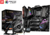
.../System/Chipset fan speed control y E-ATX Form Factor y 12 in . (30.5 cm x 27.2 cm) y Dual BIOS y 2x 256 Mb flash y UEFI AMI BIOS y ACPI 6.1, SMBIOS 2.8 y Multi-language y Drivers y DRAGON CENTER y Killer Control Center y Nahimic Audio y CPU-Z MSI GAMING y MSI App Player (BlueStacks) y Google Chrome™, Google Toolbar, Google Drive y Norton™ Internet Security Solution...
.../System/Chipset fan speed control y E-ATX Form Factor y 12 in . (30.5 cm x 27.2 cm) y Dual BIOS y 2x 256 Mb flash y UEFI AMI BIOS y ACPI 6.1, SMBIOS 2.8 y Multi-language y Drivers y DRAGON CENTER y Killer Control Center y Nahimic Audio y CPU-Z MSI GAMING y MSI App Player (BlueStacks) y Google Chrome™, Google Toolbar, Google Drive y Norton™ Internet Security Solution...

User Manual
Page 22
... CENTER ƒ GAMING HOTKEY ƒ GAMING MOUSE Control ƒ SPEED UP ƒ Total Fan Control ƒ Live Update ƒ APP Player y BIOS ƒ Click BIOS 5 ƒ Flash BIOS Button ƒ Dual BIOS 22 Specifications Special Features Continued from previous page y Performance ƒ Lightning Gen 4 PCI-E Slot ƒ Multi GPU - SLI Technology ƒ...
... CENTER ƒ GAMING HOTKEY ƒ GAMING MOUSE Control ƒ SPEED UP ƒ Total Fan Control ƒ Live Update ƒ APP Player y BIOS ƒ Click BIOS 5 ƒ Flash BIOS Button ƒ Dual BIOS 22 Specifications Special Features Continued from previous page y Performance ƒ Lightning Gen 4 PCI-E Slot ƒ Multi GPU - SLI Technology ƒ...

User Manual
Page 25
... /O Panel 25 Press and hold the Clear CMOS button for about 5-10 seconds to reset BIOS to page 67 for connecting the headphone. y Flash BIOS Button/Port - This port is used for Updating BIOS with Radeon™ Graphics) y Clear CMOS button - LAN Port LED Status Table Link/ Activity...Wi-Fi Antenna connectors Clear CMOS button PS/2 Gigabit LAN 2.5Gbps LAN USB 3.2 Gen2 Audio Ports Flash BIOS Button USB 3.2 Gen1 USB 3.2 Gen2 Type-C* Optical S/PDIF-Out USB 3.2 Gen1/ USB 3.2 Gen2* Flash BIOS Port 6.3mm headphone port *USB 3.2 Gen2 (3rd Gen AMD Ryzen™) or USB 3.2 Gen1 (...
... /O Panel 25 Press and hold the Clear CMOS button for about 5-10 seconds to reset BIOS to page 67 for connecting the headphone. y Flash BIOS Button/Port - This port is used for Updating BIOS with Radeon™ Graphics) y Clear CMOS button - LAN Port LED Status Table Link/ Activity...Wi-Fi Antenna connectors Clear CMOS button PS/2 Gigabit LAN 2.5Gbps LAN USB 3.2 Gen2 Audio Ports Flash BIOS Button USB 3.2 Gen1 USB 3.2 Gen2 Type-C* Optical S/PDIF-Out USB 3.2 Gen1/ USB 3.2 Gen2* Flash BIOS Port 6.3mm headphone port *USB 3.2 Gen2 (3rd Gen AMD Ryzen™) or USB 3.2 Gen1 (...

User Manual
Page 30
...~5 M2_1~3 OC1 PCI_E1~4 POWER1, RESET1 Processor Socket SATA1~6 T_SEN1~2 W_FLOW1 Port Type Base Clock Plus & Minus Button Multi-BIOS Switch Fan Connectors Power Connectors DIMM Slots OLED Front Audio Connector Clear CMOS (Reset BIOS) Jumper Chassis Intrusion Connector CORSAIR Connector Front Panel Connectors Low Temperature Booting Jumper LED power input Addressable RGB...
...~5 M2_1~3 OC1 PCI_E1~4 POWER1, RESET1 Processor Socket SATA1~6 T_SEN1~2 W_FLOW1 Port Type Base Clock Plus & Minus Button Multi-BIOS Switch Fan Connectors Power Connectors DIMM Slots OLED Front Audio Connector Clear CMOS (Reset BIOS) Jumper Chassis Intrusion Connector CORSAIR Connector Front Panel Connectors Low Temperature Booting Jumper LED power input Addressable RGB...

User Manual
Page 31
...properly to protect the CPU from the power outlet before booting your system. y This motherboard is necessary to prevent overheating and maintain system stability. MSI® does not guarantee the damages or risks caused by inadequate operation beyond product specifications is the Pin 1 indicator. Overview of thermal paste (... for motherboard placement. The yellow triangle is not recommended. Important y When changing the processor, the system configuration could be cleared and reset BIOS to default values, due to install a CPU heatsink. y Overheating can tolerate overclocking.
...properly to protect the CPU from the power outlet before booting your system. y This motherboard is necessary to prevent overheating and maintain system stability. MSI® does not guarantee the damages or risks caused by inadequate operation beyond product specifications is the Pin 1 indicator. Overview of thermal paste (... for motherboard placement. The yellow triangle is not recommended. Important y When changing the processor, the system configuration could be cleared and reset BIOS to default values, due to install a CPU heatsink. y Overheating can tolerate overclocking.

User Manual
Page 32
y Due to operate the memory at the marked or at a lower frequency than the amount of installed. Please refer www.msi.com for full DIMMs installation or overclocking. Go to BIOS and find the DRAM Frequency to set the memory frequency if you want to AM4 CPU/memory controller official specification limitation, the...
y Due to operate the memory at the marked or at a lower frequency than the amount of installed. Please refer www.msi.com for full DIMMs installation or overclocking. Go to BIOS and find the DRAM Frequency to set the memory frequency if you want to AM4 CPU/memory controller official specification limitation, the...
User Manual
Page 43
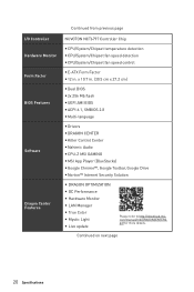
...1. Rotate the GAME BOOST knob to default values. Power on your computer. Rotate the GAME BOOST knob to HW mode in BIOS Setup. 2. Set the GAME BOOST knob to 0 and then power on the stage you selected. Overview of Components 43 The ... will automatically overclock processor depending on . OC1: GAME BOOST Knob This knob allows you to manually select a stage from number 0 (default) to hardware mode in BIOS Setup. 2. Set the GAME BOOST knob to number 11 (extreme) for overclocking the processor. Stage 0 1 2 4 6 8 10 11 Ryzen 7 2700X 2700 3.7 3.2 4.1 3.6 4.15...
...1. Rotate the GAME BOOST knob to default values. Power on your computer. Rotate the GAME BOOST knob to HW mode in BIOS Setup. 2. Set the GAME BOOST knob to 0 and then power on the stage you selected. Overview of Components 43 The ... will automatically overclock processor depending on . OC1: GAME BOOST Knob This knob allows you to manually select a stage from number 0 (default) to hardware mode in BIOS Setup. 2. Set the GAME BOOST knob to number 11 (extreme) for overclocking the processor. Stage 0 1 2 4 6 8 10 11 Ryzen 7 2700X 2700 3.7 3.2 4.1 3.6 4.15...
User Manual
Page 44
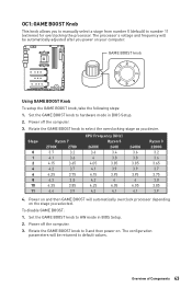
... mounting hole) and a V-Check Point. Press F10 to save and exit and then press the Enter key to Expert. 3. Adjust the relevant settings in BIOS Setup or with MSI DRAGON CENTER software. y In order to check voltages. BCLK-1 BCLK+1 Setting CPU BCLK 1. GND SOC CHIP CORE DDR 1P8 44 Overview of your...
... mounting hole) and a V-Check Point. Press F10 to save and exit and then press the Enter key to Expert. 3. Adjust the relevant settings in BIOS Setup or with MSI DRAGON CENTER software. y In order to check voltages. BCLK-1 BCLK+1 Setting CPU BCLK 1. GND SOC CHIP CORE DDR 1P8 44 Overview of your...

User Manual
Page 45
... at a stable processor frequency and to prevent the system from crashing. JSLOW1 Normal (Default) Enabled (Please enable this jumper during BIOS POST.) JLN1 Normal (Default) Enabled (Please enable this jumper during BIOS POST.) Important y Users will vary according to prevent Debug Code 00) overclocking at an extreme low temperature. y The overclocking results...
... at a stable processor frequency and to prevent the system from crashing. JSLOW1 Normal (Default) Enabled (Please enable this jumper during BIOS POST.) JLN1 Normal (Default) Enabled (Please enable this jumper during BIOS POST.) Important y Users will vary according to prevent Debug Code 00) overclocking at an extreme low temperature. y The overclocking results...
User Manual
Page 46
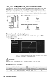
PWM Mode fan connectors provide constant 12V output and adjust fan speed with speed control signal. However, you to adjust fan speed in BIOS > HARDWARE MONITOR. Default PWM Mode fan connectors 1 CPU_FAN1 1 PUMP_FAN1 Default Auto Mode fan connectors 1 1 SYS_FAN1~4 SYS_FAN5~7 Switching fan mode and adjusting fan speed You can ...
PWM Mode fan connectors provide constant 12V output and adjust fan speed with speed control signal. However, you to adjust fan speed in BIOS > HARDWARE MONITOR. Default PWM Mode fan connectors 1 CPU_FAN1 1 PUMP_FAN1 Default Auto Mode fan connectors 1 1 SYS_FAN1~4 SYS_FAN5~7 Switching fan mode and adjusting fan speed You can ...
User Manual
Page 49
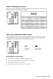
...the computer and unplug the power cord 2. Please refer to save system configuration data. Overview of Components 49 Keep Data (default) Clear CMOS/ Reset BIOS Resetting BIOS to clear the CMOS memory. Use a jumper cap to short JBAT1 for more details and usages. 2 14 1 13 1 LPC Clock 2 3V... LPC address & data pin2 10 No Pin 11 LPC address & data pin3 12 Ground 13 LPC Frame 14 Ground JBAT1: Clear CMOS (Reset BIOS) Jumper There is CMOS memory onboard that is for TPM (Trusted Platform Module). JTPM1: TPM Module Connector This connector is external powered from JBAT1....
...the computer and unplug the power cord 2. Please refer to save system configuration data. Overview of Components 49 Keep Data (default) Clear CMOS/ Reset BIOS Resetting BIOS to clear the CMOS memory. Use a jumper cap to short JBAT1 for more details and usages. 2 14 1 13 1 LPC Clock 2 3V... LPC address & data pin2 10 No Pin 11 LPC address & data pin3 12 Ground 13 LPC Frame 14 Ground JBAT1: Clear CMOS (Reset BIOS) Jumper There is CMOS memory onboard that is for TPM (Trusted Platform Module). JTPM1: TPM Module Connector This connector is external powered from JBAT1....

User Manual
Page 50
Set Chassis Intrusion to BIOS > SETTINGS > Security > Chassis Intrusion Configuration. 2. Once the chassis cover is opened again, a warning message will be displayed on screen when the computer is turned on ... JCI1 connector to connect the chassis intrusion switch cable. Go to Reset. 3. Reset Reset button Power button 50 Overview of Components Set Chassis Intrusion to BIOS > SETTINGS > Security > Chassis Intrusion Configuration. 4.
Set Chassis Intrusion to BIOS > SETTINGS > Security > Chassis Intrusion Configuration. 2. Once the chassis cover is opened again, a warning message will be displayed on screen when the computer is turned on ... JCI1 connector to connect the chassis intrusion switch cable. Go to Reset. 3. Reset Reset button Power button 50 Overview of Components Set Chassis Intrusion to BIOS > SETTINGS > Security > Chassis Intrusion Configuration. 4.

User Manual
Page 51
... is completed, the system will reboot automatically Important y Do not use the MSI DRAGON CENTER or Flash BIOS Button to flash BIOS. Before recovering, please download the latest BIOS file that matches your motherboard model from MSI website. Power on Yes to enter BIOS setup during POST. 5. Switch to reboot the system and enter the flash...
... is completed, the system will reboot automatically Important y Do not use the MSI DRAGON CENTER or Flash BIOS Button to flash BIOS. Before recovering, please download the latest BIOS file that matches your motherboard model from MSI website. Power on Yes to enter BIOS setup during POST. 5. Switch to reboot the system and enter the flash...

User Manual
Page 55
DYNAMIC DASHBOARD The DYNAMIC DASHBOARD can use MSI's software to configure and customize the DYNAMIC DASHBOARD and even upload a .gif animation file. DYNAMIC DASHBOARD DYNAMIC DASHBOARD Status Table System Status DYNAMIC DASHBOARD System ... detected or fail DRAM is not detected or fail GPU is not detected or fail Enter the OS S3 (Suspend to RAM) Flash BIOS (Update) Flash BIOS (Finish) Flash BIOS (Error) Fan Speed/ Temperature/ Voltage CPU/ VGA/ Memory information S4/S5 (Suspend to Disk/ Shutdown) User profile 256*64px .gif Important...
DYNAMIC DASHBOARD The DYNAMIC DASHBOARD can use MSI's software to configure and customize the DYNAMIC DASHBOARD and even upload a .gif animation file. DYNAMIC DASHBOARD DYNAMIC DASHBOARD Status Table System Status DYNAMIC DASHBOARD System ... detected or fail DRAM is not detected or fail GPU is not detected or fail Enter the OS S3 (Suspend to RAM) Flash BIOS (Update) Flash BIOS (Finish) Flash BIOS (Error) Fan Speed/ Temperature/ Voltage CPU/ VGA/ Memory information S4/S5 (Suspend to Disk/ Shutdown) User profile 256*64px .gif Important...

User Manual
Page 56
... LED SYS_FAN3LED SYS_FAN7 LED SYS_FAN6 LED SYS_FAN5 LED SYS_FAN4 LED LED color Red White Fan control mode PWM mode DC mode Multi-BIOS LEDs Multi-BIOS LEDs indicate which BIOS ROM is not detected or fail. VGA - Fan LEDs These LEDs indicate the fan control mode. indicates CPU is in operation.... 56 Onboard LEDs BIOS A LED (Red) BIOS B LED (White) indicates DRAM is not detected or fail. indicates the booting device is not detected or fail. DRAM - Onboard LEDs EZ ...
... LED SYS_FAN3LED SYS_FAN7 LED SYS_FAN6 LED SYS_FAN5 LED SYS_FAN4 LED LED color Red White Fan control mode PWM mode DC mode Multi-BIOS LEDs Multi-BIOS LEDs indicate which BIOS ROM is not detected or fail. VGA - Fan LEDs These LEDs indicate the fan control mode. indicates CPU is in operation.... 56 Onboard LEDs BIOS A LED (Red) BIOS B LED (White) indicates DRAM is not detected or fail. indicates the booting device is not detected or fail. DRAM - Onboard LEDs EZ ...

User Manual
Page 65
...confirmation window appears and it to confirm your choice. Ctrl+F: Enter Search page * When you are familiar with BIOS. You should be for better system performance. Important y BIOS items are for BIOS item description. Function key F1: General Help F2: Add/ Remove a favorite item F3: Enter Favorites menu F4... panel for reference only and may be slightly different from the product you purchased. y The pictures in normal conditions. BIOS Setup The default settings offer the optimal performance for system stability in this chapter are continuously update for reference only.
...confirmation window appears and it to confirm your choice. Ctrl+F: Enter Search page * When you are familiar with BIOS. You should be for better system performance. Important y BIOS items are for BIOS item description. Function key F1: General Help F2: Add/ Remove a favorite item F3: Enter Favorites menu F4... panel for reference only and may be slightly different from the product you purchased. y The pictures in normal conditions. BIOS Setup The default settings offer the optimal performance for system stability in this chapter are continuously update for reference only.
User Manual
Page 66
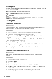
...and click on Yes to reboot the system. ƒ Reboot and press Del key during POST to perform the BIOS update process. 4. Select a BIOS file to enter BIOS. Install and launch MSI DRAGON CENTER. 2. Click Next and choose In Windows mode. After the flashing process is 100% completed, the... system will restart automatically. 66 BIOS Setup When prompted, switch to the target BIOS ROM with MSI DRAGON CENTER Before updating: Make sure the LAN driver is already installed and the Internet connection is off before...
...and click on Yes to reboot the system. ƒ Reboot and press Del key during POST to perform the BIOS update process. 4. Select a BIOS file to enter BIOS. Install and launch MSI DRAGON CENTER. 2. Click Next and choose In Windows mode. After the flashing process is 100% completed, the... system will restart automatically. 66 BIOS Setup When prompted, switch to the target BIOS ROM with MSI DRAGON CENTER Before updating: Make sure the LAN driver is already installed and the Internet connection is off before...


