
User Manual
Page 13
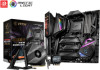
... a Processor 3 Installing DDR4 memory 5 Connecting the Front Panel Header 6 Installing the Motherboard 7 Connecting the Power Connectors 8 Installing SATA Drives 9 Installing a Graphics Card 10 Connecting Peripheral Devices 11 Power On...12 Specifications...16 JCORSAIR1 Connector Specification 23 Package contents 23 Block Diagram ...24 Rear I/O Panel...25 LAN Port LED Status Table 25 Audio Ports Configuration 25 Realtek Audio Console 26 Installing Antennas 28 Overview of Components 29 Processor Socket 31 DIMM Slots...32 PCI_E1~4: PCIe Expansion Slots 33 M2_1~3: M.2 Slots (Key...
... a Processor 3 Installing DDR4 memory 5 Connecting the Front Panel Header 6 Installing the Motherboard 7 Connecting the Power Connectors 8 Installing SATA Drives 9 Installing a Graphics Card 10 Connecting Peripheral Devices 11 Power On...12 Specifications...16 JCORSAIR1 Connector Specification 23 Package contents 23 Block Diagram ...24 Rear I/O Panel...25 LAN Port LED Status Table 25 Audio Ports Configuration 25 Realtek Audio Console 26 Installing Antennas 28 Overview of Components 29 Processor Socket 31 DIMM Slots...32 PCI_E1~4: PCIe Expansion Slots 33 M2_1~3: M.2 Slots (Key...

User Manual
Page 14
... Connector 54 DYNAMIC DASHBOARD 55 DYNAMIC DASHBOARD Status Table 55 Onboard LEDs ...56 EZ Debug LED...56 Fan LEDs...56 Multi-BIOS LEDs 56 A-XMP LED ...57 JPWRLED1: LED power input 57 CPU Power LED ...58 Debug Code LED 59 Hexadecimal Character Table 59 Boot Phases...59 Debug Code LED Table 59 ACPI States Codes 63 Installing OS, Drivers & Utilities 64 Installing Windows® 10 64 Installing Drivers 64 Installing Utilities 64 BIOS Setup ...65 Entering BIOS Setup 65 Resetting BIOS...66 Updating BIOS...66 EZ Mode ...68 Advanced Mode ...70 SETTINGS...
... Connector 54 DYNAMIC DASHBOARD 55 DYNAMIC DASHBOARD Status Table 55 Onboard LEDs ...56 EZ Debug LED...56 Fan LEDs...56 Multi-BIOS LEDs 56 A-XMP LED ...57 JPWRLED1: LED power input 57 CPU Power LED ...58 Debug Code LED 59 Hexadecimal Character Table 59 Boot Phases...59 Debug Code LED Table 59 ACPI States Codes 63 Installing OS, Drivers & Utilities 64 Installing Windows® 10 64 Installing Drivers 64 Installing Utilities 64 BIOS Setup ...65 Entering BIOS Setup 65 Resetting BIOS...66 Updating BIOS...66 EZ Mode ...68 Advanced Mode ...70 SETTINGS...
User Manual
Page 15
Save & Exit...78 OC...79 M-FLASH ...82 OC PROFILE ...83 HARDWARE MONITOR 84 Nahimic 3 ...85 Installation and Update 85 Audio Tab ...85 Microphone Tab ...86 Sound Tracker Tab 87 Settings Tab ...87 Killer Control Center 88 Configuring Bandwidth 88 AMD RAID Configuration 89 Enabling RAIDXpert2 Configuration Utility 89 Initializing Disks 90 Creating Arrays...91 Deleting Arrays ...92 Installing RAID Driver 93 Troubleshooting 94 Contents 15
Save & Exit...78 OC...79 M-FLASH ...82 OC PROFILE ...83 HARDWARE MONITOR 84 Nahimic 3 ...85 Installation and Update 85 Audio Tab ...85 Microphone Tab ...86 Sound Tracker Tab 87 Settings Tab ...87 Killer Control Center 88 Configuring Bandwidth 88 AMD RAID Configuration 89 Enabling RAIDXpert2 Configuration Utility 89 Initializing Disks 90 Creating Arrays...91 Deleting Arrays ...92 Installing RAID Driver 93 Troubleshooting 94 Contents 15

User Manual
Page 17
... AMD Ryzen™ with Radeon™ Graphics) 2242/ 2260/ 2280/ 22110 storage devices *The speeds may vary for different devices y Supports RAID 0, RAID 1 and RAID 10 for X570 Chipset SATA storage devices y Supports RAID 0, RAID 1 and RAID 10 for M.2 NVMe storage devices y 1x Killer® E2600 Gigabit LAN Controller y 1x Killer® E3000 2.5 Gbps LAN Controller Killer™ Wi-Fi 6 AX1650 Chipset y The Wireless module is pre-install in the M2_4 (Key-E) slot y Supports Wi-Fi 802.11 a/b/g/n/ac/ax, dual...
... AMD Ryzen™ with Radeon™ Graphics) 2242/ 2260/ 2280/ 22110 storage devices *The speeds may vary for different devices y Supports RAID 0, RAID 1 and RAID 10 for X570 Chipset SATA storage devices y Supports RAID 0, RAID 1 and RAID 10 for M.2 NVMe storage devices y 1x Killer® E2600 Gigabit LAN Controller y 1x Killer® E3000 2.5 Gbps LAN Controller Killer™ Wi-Fi 6 AX1650 Chipset y The Wireless module is pre-install in the M2_4 (Key-E) slot y Supports Wi-Fi 802.11 a/b/g/n/ac/ax, dual...

User Manual
Page 19
... 4 USB 2.0 ports) y 1x 4-pin CPU fan connector y 1x 4-pin Water Pump connector y 7x 4-pin system fan connectors y 1x 3-pin Water Flow connector y 1x Front panel audio connector y 2x System panel connectors y 1x Chassis Intrusion connector y 2x 2-pin Thermal Sensors connectors y 1x 4-pin RGB LED connector y 2x 3-pin RAINBOW LED connectors y 1x 3-pin CORSAIR LED connector y 1x GAME BOOST knob y 1x BCLK+1 button y 1x BCLK-1 button y 1x Power button y 1x Reset button Switch y 1x Multi-BIOS switch Jumper Debug LED Display Panel y 1x Slow mode jumper y 1x Low temperature booting jumper y 1x...
... 4 USB 2.0 ports) y 1x 4-pin CPU fan connector y 1x 4-pin Water Pump connector y 7x 4-pin system fan connectors y 1x 3-pin Water Flow connector y 1x Front panel audio connector y 2x System panel connectors y 1x Chassis Intrusion connector y 2x 2-pin Thermal Sensors connectors y 1x 4-pin RGB LED connector y 2x 3-pin RAINBOW LED connectors y 1x 3-pin CORSAIR LED connector y 1x GAME BOOST knob y 1x BCLK+1 button y 1x BCLK-1 button y 1x Power button y 1x Reset button Switch y 1x Multi-BIOS switch Jumper Debug LED Display Panel y 1x Slow mode jumper y 1x Low temperature booting jumper y 1x...

User Manual
Page 53
... LED strips. In the case of Components 53 y Always turn off the power supply and unplug the power cord from the power outlet before installing or removing the RGB LED strip. The JRGB connector and the JRAINBOW connector provide different voltages, and connecting the 5V LED strip to the JRGB connector will result in damage to control the extended LED strip. Important y The JRAINBOW connector supports up to 200 LEDs. y Please use MSI's software...
... LED strips. In the case of Components 53 y Always turn off the power supply and unplug the power cord from the power outlet before installing or removing the RGB LED strip. The JRGB connector and the JRAINBOW connector provide different voltages, and connecting the 5V LED strip to the JRGB connector will result in damage to control the extended LED strip. Important y The JRAINBOW connector supports up to 200 LEDs. y Please use MSI's software...

User Manual
Page 60
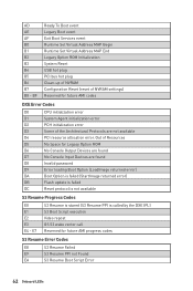
... module specific) Post-Memory PCH initialization is started Post-Memory PCH initialization (PCH module specific) DXE IPL is started PEI Error Codes 4B Memory not installed (For Summit CPU) E0 Memory not installed (For Bristol CPU) DXE Progress Codes 60 DXE Core is started 61 NVRAM initialization 62 Installation of the PCH Runtime Services 63 CPU DXE initialization is started 60 Onboard LEDs Serial Presence Detect (SPD) data reading Memory initialization. Application Processor(s) (AP) initialization CPU post-memory initialization. Memory presence detection Memory...
... module specific) Post-Memory PCH initialization is started Post-Memory PCH initialization (PCH module specific) DXE IPL is started PEI Error Codes 4B Memory not installed (For Summit CPU) E0 Memory not installed (For Bristol CPU) DXE Progress Codes 60 DXE Core is started 61 NVRAM initialization 62 Installation of the PCH Runtime Services 63 CPU DXE initialization is started 60 Onboard LEDs Serial Presence Detect (SPD) data reading Memory initialization. Application Processor(s) (AP) initialization CPU post-memory initialization. Memory presence detection Memory...
User Manual
Page 62
... To Boot event Legacy Boot event Exit Boot Services event Runtime Set Virtual Address MAP Begin Runtime Set Virtual Address MAP End Legacy Option ROM Initialization System Reset USB hot plug PCI bus hot plug Clean-up of NVRAM Configuration Reset (reset of NVRAM settings) Reserved for future AMI codes DXE Error Codes D0 CPU initialization error D1 System Agent initialization error D2 PCH initialization error D3 Some of Resources D5 No Space for Legacy Option ROM D6 No Console Output Devices are...
... To Boot event Legacy Boot event Exit Boot Services event Runtime Set Virtual Address MAP Begin Runtime Set Virtual Address MAP End Legacy Option ROM Initialization System Reset USB hot plug PCI bus hot plug Clean-up of NVRAM Configuration Reset (reset of NVRAM settings) Reserved for future AMI codes DXE Error Codes D0 CPU initialization error D1 System Agent initialization error D2 PCH initialization error D3 Some of Resources D5 No Space for Legacy Option ROM D6 No Console Output Devices are...
User Manual
Page 64
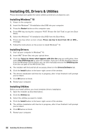
message. 7. Follow the instructions on the computer. 2. Insert MSI® Driver Disc into your computer. If you turn off the AutoPlay feature from the Windows Control Panel, you can still manually execute the DVDSetup.exe from CD or DVD... Select the utilities you must complete drivers installation. 1. Click OK button to finish. 8. Power on the screen to install Windows® 10. Press F11 key during the computer POST (Power-On Self...
message. 7. Follow the instructions on the computer. 2. Insert MSI® Driver Disc into your computer. If you turn off the AutoPlay feature from the Windows Control Panel, you can still manually execute the DVDSetup.exe from CD or DVD... Select the utilities you must complete drivers installation. 1. Click OK button to finish. 8. Power on the screen to install Windows® 10. Press F11 key during the computer POST (Power-On Self...
User Manual
Page 66
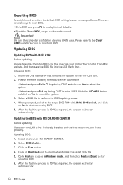
... USB flash drive that matches your motherboard model from MSI website. Click Next and choose In Windows mode. After the flashing process is off before clearing CMOS data. Click on the motherboard. y Short the Clear CMOS jumper on Scan button. 4. Important Be sure the computer is 100% completed, the system will reboot automatically. And then save the BIOS file into the USB port. 2. Select BIOS Update. 3. And then click Next and Start to download and install...
... USB flash drive that matches your motherboard model from MSI website. Click Next and choose In Windows mode. After the flashing process is off before clearing CMOS data. Click on the motherboard. y Short the Clear CMOS jumper on Scan button. 4. Important Be sure the computer is 100% completed, the system will reboot automatically. And then save the BIOS file into the USB port. 2. Select BIOS Update. 3. And then click Next and Start to download and install...

User Manual
Page 68
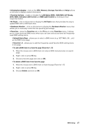
... the CPU/ DDR speed, CPU/ MB temperature, MB/ CPU type, memory size, CPU/ DDR voltage, BIOS version and build date. This switch will only be available if the installed processor supports this function. y Language - you to search by clicking on the question mark in OC menu and don't load defaults to keep the optimal performance and system stability after activating the GAME Boost function. EZ Mode At EZ mode, it to USB flash drive...
... the CPU/ DDR speed, CPU/ MB temperature, MB/ CPU type, memory size, CPU/ DDR voltage, BIOS version and build date. This switch will only be available if the installed processor supports this function. y Language - you to search by clicking on the question mark in OC menu and don't load defaults to keep the optimal performance and system stability after activating the GAME Boost function. EZ Mode At EZ mode, it to USB flash drive...
User Manual
Page 69
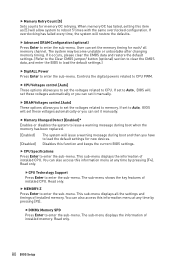
... not only on BIOS menu but also on their respective button. Move the mouse over a BIOS item on OK. ƒ To delete a BIOS item from favorite page 1. enable or disable the LAN Option ROM, CSM/UEFI, ErP Ready, AHCI, RAID, Indication LED Control and RGB Light Control by percentage. y M-Flash - Right-click or press F2 key. 3. BIOS Setup 69 press the Favorites tab or the F3 key to manually control the fan speed by clicking on...
... not only on BIOS menu but also on their respective button. Move the mouse over a BIOS item on OK. ƒ To delete a BIOS item from favorite page 1. enable or disable the LAN Option ROM, CSM/UEFI, ErP Ready, AHCI, RAID, Indication LED Control and RGB Light Control by percentage. y M-Flash - Right-click or press F2 key. 3. BIOS Setup 69 press the Favorites tab or the F3 key to manually control the fan speed by clicking on...

User Manual
Page 72
...Enables the onboard LAN Boot ROM. [Disabled] Disables the onboard LAN Boot ROM. 72 BIOS Setup fLAN Option ROM [Disabled] Enables or disables the legacy network Boot Option ROM for detailed settings. This item will appear when Onboard LAN Controller is only available if the system supports 64-bit PCI decoding. [Enabled] Allows you to utilize more than 4x GPUs. [Disabled] Disables this function. f Integrated Peripherals Sets integrated peripherals'parameters, such as LAN, HDD, USB and audio. fPCI_EX - Max Link Speed [Auto] Sets PCI Express protocol of the onboard Power LED. [Dual...
...Enables the onboard LAN Boot ROM. [Disabled] Disables the onboard LAN Boot ROM. 72 BIOS Setup fLAN Option ROM [Disabled] Enables or disables the legacy network Boot Option ROM for detailed settings. This item will appear when Onboard LAN Controller is only available if the system supports 64-bit PCI decoding. [Enabled] Allows you to utilize more than 4x GPUs. [Disabled] Disables this function. f Integrated Peripherals Sets integrated peripherals'parameters, such as LAN, HDD, USB and audio. fPCI_EX - Max Link Speed [Auto] Sets PCI Express protocol of the onboard Power LED. [Dual...

User Manual
Page 73
... legacy mode. [Disabled] The USB devices will support Ipv6 protocol. fOnboard Wi-Fi Module Control [Enabled] Enables or disables the onboard Wi-Fi module controller. fSATAx Hot Plug [Disabled] Allows user to enable or disable the SATA hot plug support. [Enabled] Enables hot plug support for the SATA ports. [Disabled] Disables hot plug support for SATA storage devices. fXHCI Hand-off [Enabled] Enables or disables XHCI hand-off feature. AHCI (Advanced Host Controller Interface) offers some advanced features to enter the submenu. BIOS Setup 73 fNetwork Stack [Disabled] Sets UEFI network...
... legacy mode. [Disabled] The USB devices will support Ipv6 protocol. fOnboard Wi-Fi Module Control [Enabled] Enables or disables the onboard Wi-Fi module controller. fSATAx Hot Plug [Disabled] Allows user to enable or disable the SATA hot plug support. [Enabled] Enables hot plug support for the SATA ports. [Disabled] Disables hot plug support for SATA storage devices. fXHCI Hand-off [Enabled] Enables or disables XHCI hand-off feature. AHCI (Advanced Host Controller Interface) offers some advanced features to enter the submenu. BIOS Setup 73 fNetwork Stack [Disabled] Sets UEFI network...

User Manual
Page 74
... BIOS Setup This sub-menu will appear when BIOS UEFI/CSM Mode is enabled. fSystem Power Fault Protection [Disabled] Enables or disables the system to enter the sub-menu. fBIOS UEFI/CSM Mode [CSM] Select CSM or UEFI for different sleep modes. It will not support S4 & S5 wake up by OS. f Power Management Setup Sets system Power Management of these items. [OS] The wake up events will be defined by USB and PCIe devices. [Disabled] Disables this...
... BIOS Setup This sub-menu will appear when BIOS UEFI/CSM Mode is enabled. fSystem Power Fault Protection [Disabled] Enables or disables the system to enter the sub-menu. fBIOS UEFI/CSM Mode [CSM] Select CSM or UEFI for different sleep modes. It will not support S4 & S5 wake up by OS. f Power Management Setup Sets system Power Management of these items. [OS] The wake up events will be defined by USB and PCIe devices. [Disabled] Disables this...

User Manual
Page 75
... the power saving modes when activity or input signal of USB device is detected. [Disabled] Disables this function. fResume by USB Device [Disabled] Disables or enables system wake up function of installed PCI/ PCI-E expansion cards, integrated LAN controllers or USB devices which are supported by USB device. [Enabled] Enables the system to be awakened from sleep state when activity of PCI/ PCIe device is detected. [Disabled] Disables this function. fResume From S3/S4/S5 by PS/2 Keyboard [Disabled] Enables or disables the system wake up...
... the power saving modes when activity or input signal of USB device is detected. [Disabled] Disables this function. fResume by USB Device [Disabled] Disables or enables system wake up function of installed PCI/ PCI-E expansion cards, integrated LAN controllers or USB devices which are supported by USB device. [Enabled] Enables the system to be awakened from sleep state when activity of PCI/ PCIe device is detected. [Disabled] Disables this function. fResume From S3/S4/S5 by PS/2 Keyboard [Disabled] Enables or disables the system wake up...
User Manual
Page 80
... during boot and then you can set it manually. f CPU Specifications Press Enter to enter the sub-menu. fCPU Technology Support Press Enter to enter the sub-menu. f MEMORY-Z Press Enter to CPU PWM. This sub-menu displays all memory channel. Controls the digital powers related to enter the sub-menu. f DRAM Voltages control [Auto] These options allows you can also access this function and keeps the current BIOS settings. Read only. The sub-menu displays the information of installed CPU. User can set the memory...
... during boot and then you can set it manually. f CPU Specifications Press Enter to enter the sub-menu. fCPU Technology Support Press Enter to enter the sub-menu. f MEMORY-Z Press Enter to CPU PWM. This sub-menu displays all memory channel. Controls the digital powers related to enter the sub-menu. f DRAM Voltages control [Auto] These options allows you can also access this function and keeps the current BIOS settings. Read only. The sub-menu displays the information of installed CPU. User can set the memory...
User Manual
Page 85
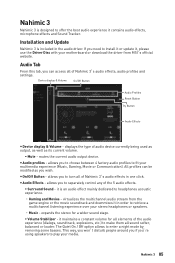
...; Surround Sound - Device display & Volume On/Off Button Audio Profiles Reset Button Try Button Audio Effects y Device display & Volume - Nahimic 3 85 y Audio profiles - it in order to retrieve a multichannel listening experience over your motherboard or download the driver from the game engine or the movie soundtrack and downmixes it is an audio effect mainly dedicated to separately control any of Nahimic 3's audio effects in the audio driver. virtualizes the multichannel audio stream from MSI...
...; Surround Sound - Device display & Volume On/Off Button Audio Profiles Reset Button Try Button Audio Effects y Device display & Volume - Nahimic 3 85 y Audio profiles - it in order to retrieve a multichannel listening experience over your motherboard or download the driver from the game engine or the movie soundtrack and downmixes it is an audio effect mainly dedicated to separately control any of Nahimic 3's audio effects in the audio driver. virtualizes the multichannel audio stream from MSI...
User Manual
Page 93
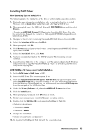
.... 7. You have successfully installed the RAID driver, and Windows setup should continue. 9. Re-log into the optical drive. Click the Install button. 6. When prompt you can still manually execute the DVDSetup.exe from the root path of the drivers while installing operating system. 1. Set the SATA Mode to choose what happens with AMD RAID Drivers and then click Browse. ƒ To make an AMD RAID Drivers USB flash drive. Click Browse and navigate...
.... 7. You have successfully installed the RAID driver, and Windows setup should continue. 9. Re-log into the optical drive. Click the Install button. 6. When prompt you can still manually execute the DVDSetup.exe from the root path of the drivers while installing operating system. 1. Set the SATA Mode to choose what happens with AMD RAID Drivers and then click Browse. ƒ To make an AMD RAID Drivers USB flash drive. Click Browse and navigate...

User Manual
Page 94
... Windows® Device Manager. ∙∙Connect the USB device to other USB port on the monitor. ∙∙If 3 long beeps are heard, remove all memory modules and try to go over troubleshooting guide first to JFP1 pin header properly. ∙∙Verify the Clear CMOS jumper JBAT1 is turned on. ∙∙Select different inputs on the motherboard rear IO panel. The power is listed in the BIOS. Troubleshooting Before sending the motherboard for motherboard with Dual BIOS...
... Windows® Device Manager. ∙∙Connect the USB device to other USB port on the monitor. ∙∙If 3 long beeps are heard, remove all memory modules and try to go over troubleshooting guide first to JFP1 pin header properly. ∙∙Verify the Clear CMOS jumper JBAT1 is turned on. ∙∙Select different inputs on the motherboard rear IO panel. The power is listed in the BIOS. Troubleshooting Before sending the motherboard for motherboard with Dual BIOS...


