User Manual
Page 11
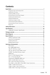
... Realtek Audio Console 24 Overview of Components 26 CPU Socket ...28 OC1: GAME BOOST Knob 31 JOC_RT1: OC Retry Jumper 32 JOC_FS1: OC Force Enter BIOS Jumper 32 JSLOW1: Slow Mode Booting Jumper 33 DIMM Slots...33 PCI_E1~5: PCIe Expansion Slots 36 M2_1~3: M.2 Slots (Key M 39 Installing M.2 XPANDER-AERO card 41...
... Realtek Audio Console 24 Overview of Components 26 CPU Socket ...28 OC1: GAME BOOST Knob 31 JOC_RT1: OC Retry Jumper 32 JOC_FS1: OC Force Enter BIOS Jumper 32 JSLOW1: Slow Mode Booting Jumper 33 DIMM Slots...33 PCI_E1~5: PCIe Expansion Slots 36 M2_1~3: M.2 Slots (Key M 39 Installing M.2 XPANDER-AERO card 41...
User Manual
Page 12
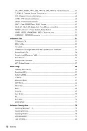
... Thermal Sensor Connectors 47 JCI1: Chassis Intrusion Connector 48 JTPM1: TPM Module Connector 48 JAUD1: Front Audio Connector 49 JBAT1: Clear CMOS (Reset BIOS) Jumper 49 JBLK_U1, JBLK_D1: Base clock Plus, Minus connectors 50 POWER1, RESET1: Power Button, Reset Button 50 JRGB1, JRGB2, JRAINBOW1: RGB...Debug Code LED 54 Hexadecimal Character Table 54 Boot Phases...54 Debug Code LED Table 55 ACPI States Codes 57 BIOS Setup ...58 Entering BIOS Setup 58 Resetting BIOS...59 Updating BIOS...59 EZ Mode ...61 Advanced Mode ...63 SETTINGS...64 Advanced...64 Boot...68 Security ...69 Save & Exit...
... Thermal Sensor Connectors 47 JCI1: Chassis Intrusion Connector 48 JTPM1: TPM Module Connector 48 JAUD1: Front Audio Connector 49 JBAT1: Clear CMOS (Reset BIOS) Jumper 49 JBLK_U1, JBLK_D1: Base clock Plus, Minus connectors 50 POWER1, RESET1: Power Button, Reset Button 50 JRGB1, JRGB2, JRAINBOW1: RGB...Debug Code LED 54 Hexadecimal Character Table 54 Boot Phases...54 Debug Code LED Table 55 ACPI States Codes 57 BIOS Setup ...58 Entering BIOS Setup 58 Resetting BIOS...59 Updating BIOS...59 EZ Mode ...61 Advanced Mode ...63 SETTINGS...64 Advanced...64 Boot...68 Security ...69 Save & Exit...
User Manual
Page 16
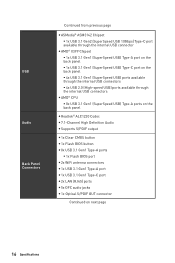
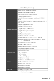
... page y ASMedia® ASM3142 Chipset ƒ 1x USB 3.1 Gen2 (SuperSpeed USB 10Gbps) Type-C port available through the internal USB connector y AMD® X399 Chipset ƒ 1x USB 3.1 Gen1 (SuperSpeed USB) Type-A port on the back panel ƒ 1x USB 3.1 Gen1 (SuperSpeed USB) Type-C port on...back panel y Realtek® ALC1220 Codec y 7.1-Channel High Definition Audio y Supports S/PDIF output y 1x Clear CMOS button y 1x Flash BIOS button y 8x USB 3.1 Gen1 Type-A ports ƒ 1x Flash BIOS port y 2x WiFi antenna connectors y 1x USB 3.1 Gen1 Type-A port y 1x USB 3.1 Gen1 Type-C port y 2x LAN (RJ45...
... page y ASMedia® ASM3142 Chipset ƒ 1x USB 3.1 Gen2 (SuperSpeed USB 10Gbps) Type-C port available through the internal USB connector y AMD® X399 Chipset ƒ 1x USB 3.1 Gen1 (SuperSpeed USB) Type-A port on the back panel ƒ 1x USB 3.1 Gen1 (SuperSpeed USB) Type-C port on...back panel y Realtek® ALC1220 Codec y 7.1-Channel High Definition Audio y Supports S/PDIF output y 1x Clear CMOS button y 1x Flash BIOS button y 8x USB 3.1 Gen1 Type-A ports ƒ 1x Flash BIOS port y 2x WiFi antenna connectors y 1x USB 3.1 Gen1 Type-A port y 1x USB 3.1 Gen1 Type-C port y 2x LAN (RJ45...
User Manual
Page 17
... PCIe x16 slots y 1x GAME BOOST knob y 1x Power button y 1x Reset button y 1x Clear CMOS jumper y 1x OC retry connector y 1x OC force enter BIOS connector y 1x Chassis Intrusion connector y 1x Slow mode connector y 1x JBLK_U1 connector y 1x JBLK_D1 connector Debug LED y 1x 2-Digit Debug Code LED Continued on next...
... PCIe x16 slots y 1x GAME BOOST knob y 1x Power button y 1x Reset button y 1x Clear CMOS jumper y 1x OC retry connector y 1x OC force enter BIOS connector y 1x Chassis Intrusion connector y 1x Slow mode connector y 1x JBLK_U1 connector y 1x JBLK_D1 connector Debug LED y 1x 2-Digit Debug Code LED Continued on next...
User Manual
Page 18
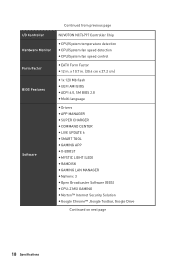
...detection y CPU/System fan speed control y EATX Form Factor y 12 in . (30.4 cm x 27.2 cm) y 1x 128 Mb flash y UEFI AMI BIOS y ACPI 6.0, SM BIOS 2.8 y Multi-language y Drivers y APP MANAGER y SUPER CHARGER y COMMAND CENTER y LIVE UPDATE 6 y SMART TOOL y GAMING APP y X-BOOST y MYSTIC ...LIGHT (LED) y RAMDISK y GAMING LAN MANAGER y Nahimic 3 y Open Broadcaster Software (OBS) y CPU-Z MSI GAMING y Norton™ Internet Security Solution y Google ...
...detection y CPU/System fan speed control y EATX Form Factor y 12 in . (30.4 cm x 27.2 cm) y 1x 128 Mb flash y UEFI AMI BIOS y ACPI 6.0, SM BIOS 2.8 y Multi-language y Drivers y APP MANAGER y SUPER CHARGER y COMMAND CENTER y LIVE UPDATE 6 y SMART TOOL y GAMING APP y X-BOOST y MYSTIC ...LIGHT (LED) y RAMDISK y GAMING LAN MANAGER y Nahimic 3 y Open Broadcaster Software (OBS) y CPU-Z MSI GAMING y Norton™ Internet Security Solution y Google ...
User Manual
Page 19
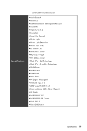
... page y Audio Boost 4 y Nahimic 3 y GAMING LAN with type A+C y AMD Turbo USB3.1 Gen 1 y Front Lightning USB 3.1 Gen 2 Type-C y VR Ready y GAMING HOTKEY y GAMING MOUSE Control y Click BIOS 5 y Flash BIOS button Specifications 19
... page y Audio Boost 4 y Nahimic 3 y GAMING LAN with type A+C y AMD Turbo USB3.1 Gen 1 y Front Lightning USB 3.1 Gen 2 Type-C y VR Ready y GAMING HOTKEY y GAMING MOUSE Control y Click BIOS 5 y Flash BIOS button Specifications 19
User Manual
Page 22
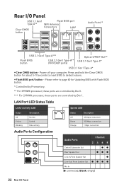
... *** For 2990WX processor, these ports are controlled by Die 1. Please refer to page 60 for about 5-10 seconds to reset BIOS to default values. LAN Port LED Status Table Link/ Activity LED Status Off Yellow Blinking Description No link Linked Data activity Speed ...Front Speaker Out Mic In (●: connected, Blank: empty) 22 Rear I /O Panel USB 3.1 Gen1 Flash BIOS port Type-A** WiFi Antenna Clear CMOS Connectors LAN* button Audio Ports** USB 3.1 Gen1 Type-A*** Flash BIOS button USB 3.1 Gen1 Type-A** (VR READY ports) Optical S/PDIF-Out** USB 3.1 Gen1 Type-C* USB 3.1 ...
... *** For 2990WX processor, these ports are controlled by Die 1. Please refer to page 60 for about 5-10 seconds to reset BIOS to default values. LAN Port LED Status Table Link/ Activity LED Status Off Yellow Blinking Description No link Linked Data activity Speed ...Front Speaker Out Mic In (●: connected, Blank: empty) 22 Rear I /O Panel USB 3.1 Gen1 Flash BIOS port Type-A** WiFi Antenna Clear CMOS Connectors LAN* button Audio Ports** USB 3.1 Gen1 Type-A*** Flash BIOS button USB 3.1 Gen1 Type-A** (VR READY ports) Optical S/PDIF-Out** USB 3.1 Gen1 Type-C* USB 3.1 ...
User Manual
Page 27
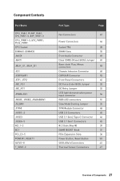
... SATA1~8 T_SEN1~3 Port Type Page Fan Connectors 47 Power Connectors 44 Socket TR4 28 DIMM Slots 33 Front Audio Connector 49 Clear CMOS (Reset BIOS) Jumper 49 Base clock Plus, Minus connectors 50 Chassis Intrusion Connector 48 CORSAIR Connector 52 Front Panel Connectors 43 OC Force Enter... BIOS Jumper 32 OC Retry Jumper 32 LED light demonstration power input connector 54 RGB LED connectors 51 Slow Mode Booting Jumper 33 TPM ...
... SATA1~8 T_SEN1~3 Port Type Page Fan Connectors 47 Power Connectors 44 Socket TR4 28 DIMM Slots 33 Front Audio Connector 49 Clear CMOS (Reset BIOS) Jumper 49 Base clock Plus, Minus connectors 50 Chassis Intrusion Connector 48 CORSAIR Connector 52 Front Panel Connectors 43 OC Force Enter... BIOS Jumper 32 OC Retry Jumper 32 LED light demonstration power input connector 54 RGB LED connectors 51 Slow Mode Booting Jumper 33 TPM ...
User Manual
Page 31
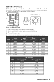
... of Components 31 Set the GAME BOOST knob to select the overclocking stage as you desire. Rotate the GAME BOOST knob to hardware mode in BIOS Setup. 2. OC1: GAME BOOST Knob This knob allows you power on your computer. The processor's voltage and frequency will be automatically adjusted after you to...
... of Components 31 Set the GAME BOOST knob to select the overclocking stage as you desire. Rotate the GAME BOOST knob to hardware mode in BIOS Setup. 2. OC1: GAME BOOST Knob This knob allows you power on your computer. The processor's voltage and frequency will be automatically adjusted after you to...

User Manual
Page 32
... GAME BOOST overclocking range or the damages/ risks caused by overclocking behavior. JOC_FS1: OC Force Enter BIOS Jumper When you selected. Important y You can also control the GAME BOOST function in the BIOS > OC menu unchanged. y MSI components are recommended for better compatibility when using GAME BOOST function. JOC_RT1 Normal (default) Keep retrying...
... GAME BOOST overclocking range or the damages/ risks caused by overclocking behavior. JOC_FS1: OC Force Enter BIOS Jumper When you selected. Important y You can also control the GAME BOOST function in the BIOS > OC menu unchanged. y MSI components are recommended for better compatibility when using GAME BOOST function. JOC_RT1 Normal (default) Keep retrying...
User Manual
Page 33
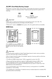
... 32-bit Windows OS due to the memory address limitation. y The stability and compatibility of Components 33 Normal (default) Enabled (Please enable this jumper during BIOS POST.) Important y Users will be a little less than 4GB memory on installed CPU and devices when overclocking. DIMM Slots Die 0* Die 1* * For 2990WX processor, DIMMC1...
... 32-bit Windows OS due to the memory address limitation. y The stability and compatibility of Components 33 Normal (default) Enabled (Please enable this jumper during BIOS POST.) Important y Users will be a little less than 4GB memory on installed CPU and devices when overclocking. DIMM Slots Die 0* Die 1* * For 2990WX processor, DIMMC1...
User Manual
Page 47
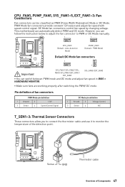
... 2 Voltage Control 3 Sense 4 NC T_SEN1~3: Thermal Sensor Connectors These connectors allow you can switch between PWM mode and DC mode and adjust fan speed in BIOS > HARDWARE MONITOR. CPU_FAN1, PUMP_FAN1, SYS_FAN1~5, EXT_FAN1~3: Fan Connectors Fan connectors can automatically detect PWM and DC mode. Pin definition of Components 47 PWM Mode fan...
... 2 Voltage Control 3 Sense 4 NC T_SEN1~3: Thermal Sensor Connectors These connectors allow you can switch between PWM mode and DC mode and adjust fan speed in BIOS > HARDWARE MONITOR. CPU_FAN1, PUMP_FAN1, SYS_FAN1~5, EXT_FAN1~3: Fan Connectors Fan connectors can automatically detect PWM and DC mode. Pin definition of Components 47 PWM Mode fan...
User Manual
Page 48
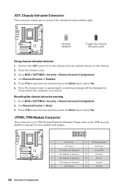
... the chassis intrusion switch cable. JTPM1: TPM Module Connector This connector is turned on the chassis. 2. JCI1: Chassis Intrusion Connector This connector allows you to BIOS > SETTINGS > Security > Chassis Intrusion Configuration. 2. Resetting the chassis intrusion warning 1. Go to Enabled. 5. Close the chassis cover. 3. Set Chassis Intrusion to...
... the chassis intrusion switch cable. JTPM1: TPM Module Connector This connector is turned on the chassis. 2. JCI1: Chassis Intrusion Connector This connector allows you to BIOS > SETTINGS > Security > Chassis Intrusion Configuration. 2. Resetting the chassis intrusion warning 1. Go to Enabled. 5. Close the chassis cover. 3. Set Chassis Intrusion to...
User Manual
Page 49
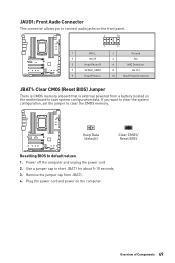
... system configuration, set the jumper to clear the CMOS memory. If you to connect audio jacks on the computer. Keep Data (default) Clear CMOS/ Reset BIOS Resetting BIOS to short JBAT1 for about 5-10 seconds. 3. Plug the power cord and power on the front panel. 2 10 1 9 1 MIC L 2 Ground 3 MIC R 4 NC 5 ...Head Phone R 6 MIC Detection 7 SENSE_SEND 8 No Pin 9 Head Phone L 10 Head Phone Detection JBAT1: Clear CMOS (Reset BIOS) Jumper There is CMOS memory onboard that is external powered from JBAT1. 4.
... system configuration, set the jumper to clear the CMOS memory. If you to connect audio jacks on the computer. Keep Data (default) Clear CMOS/ Reset BIOS Resetting BIOS to short JBAT1 for about 5-10 seconds. 3. Plug the power cord and power on the front panel. 2 10 1 9 1 MIC L 2 Ground 3 MIC R 4 NC 5 ...Head Phone R 6 MIC Detection 7 SENSE_SEND 8 No Pin 9 Head Phone L 10 Head Phone Detection JBAT1: Clear CMOS (Reset BIOS) Jumper There is CMOS memory onboard that is external powered from JBAT1. 4.
User Manual
Page 58
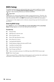
... and it to USB flash drive (FAT/ FAT32 format only). Important y BIOS items are familiar with BIOS. You could also refer to enter Boot Menu message appears on the screen during the boot process. Entering BIOS Setup Press Delete key, when the Press DEL key to enter Setup Menu,... F11 to the HELP information panel for BIOS item description. Therefore, the description may vary from the latest BIOS and should always keep the default settings to confirm your choice. 58 BIOS Setup Ctrl+F: Enter Search page * When you purchased. BIOS Setup The default settings offer the optimal ...
... and it to USB flash drive (FAT/ FAT32 format only). Important y BIOS items are familiar with BIOS. You could also refer to enter Boot Menu message appears on the screen during the boot process. Entering BIOS Setup Press Delete key, when the Press DEL key to enter Setup Menu,... F11 to the HELP information panel for BIOS item description. Therefore, the description may vary from the latest BIOS and should always keep the default settings to confirm your choice. 58 BIOS Setup Ctrl+F: Enter Search page * When you purchased. BIOS Setup The default settings offer the optimal ...
User Manual
Page 59
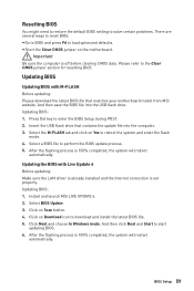
...is 100% completed, the system will restart automatically. And then save the BIOS file into the computer. 3. Select the M-FLASH tab and click on Download icon to load optimized defaults. Install and launch MSI LIVE UPDATE 6. 2. Please refer to reboot the system and enter the... flash mode. 4. Select BIOS Update. 3. And then click Next and Start to start updating BIOS. 6. Updating BIOS: 1. Click Next and choose In Windows mode. ...
...is 100% completed, the system will restart automatically. And then save the BIOS file into the computer. 3. Select the M-FLASH tab and click on Download icon to load optimized defaults. Install and launch MSI LIVE UPDATE 6. 2. Please refer to reboot the system and enter the... flash mode. 4. Select BIOS Update. 3. And then click Next and Start to start updating BIOS. 6. Updating BIOS: 1. Click Next and choose In Windows mode. ...
User Manual
Page 60
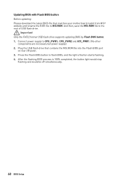
..., the button light would stop flashing and would be off simultaneously. 60 BIOS Setup Updating BIOS with Flash BIOS button Before updating: Please download the latest BIOS file that contains the MSI.ROM file into the Flash BIOS port on rear I/O panel. 3. Plug the USB flash drive that matches... your motherboard model from MSI® website and rename the BIOS file to CPU_PWR1,CPU_PWR2 and ATX_PWR1. (No other components...
..., the button light would stop flashing and would be off simultaneously. 60 BIOS Setup Updating BIOS with Flash BIOS button Before updating: Please download the latest BIOS file that contains the MSI.ROM file into the Flash BIOS port on rear I/O panel. 3. Plug the USB flash drive that matches... your motherboard model from MSI® website and rename the BIOS file to CPU_PWR1,CPU_PWR2 and ATX_PWR1. (No other components...
User Manual
Page 61
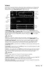
...this tab or the F12 key to take a screenshot and save it provides the basic system information and allows you to select the language of BIOS setup. Switch the outer circle to select the memory profile if any changes in OC menu and don't load defaults to keep the optimal ... y Language - You can move the device icons to switch GAME BOOST control between Advanced mode and EZ mode. allows you to find the item listing. BIOS Setup 61 The boot priority from high to low is left to search by pressing the Setup Mode switch or F7 function key. y Screenshot - y System...
...this tab or the F12 key to take a screenshot and save it provides the basic system information and allows you to select the language of BIOS setup. Switch the outer circle to select the memory profile if any changes in OC menu and don't load defaults to keep the optimal ... y Language - You can move the device icons to switch GAME BOOST control between Advanced mode and EZ mode. allows you to find the item listing. BIOS Setup 61 The boot priority from high to low is left to search by pressing the Setup Mode switch or F7 function key. y Screenshot - y System...
User Manual
Page 62
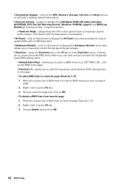
...display related information. y Function buttons - y M-Flash - y Hardware Monitor - click on favorite page (Favorite 1~5) 2. Move the mouse over a BIOS item on this button to update BIOS with a USB flash drive. Right-click or press F2 key. 3. enable or disable the LAN Option ROM, HD audio controller, AHCI/RAID..., CPU Fan Fail Warning Control, Windows 10 WHQL support and BIOS Log Review by percentage. Move the mouse over a BIOS item not only on BIOS menu but also on this button to display the Hardware Monitor menu that provides the way to ...
...display related information. y Function buttons - y M-Flash - y Hardware Monitor - click on favorite page (Favorite 1~5) 2. Move the mouse over a BIOS item on this button to update BIOS with a USB flash drive. Right-click or press F2 key. 3. enable or disable the LAN Option ROM, HD audio controller, AHCI/RAID..., CPU Fan Fail Warning Control, Windows 10 WHQL support and BIOS Log Review by percentage. Move the mouse over a BIOS item not only on BIOS menu but also on this button to display the Hardware Monitor menu that provides the way to ...
User Manual
Page 63
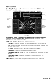
...ƒ OC - A-XMP switch Setup Mode switch Screenshot Search Language System information GAME BOOST switch Boot device priority bar BIOS menu selection BIOS menu selection Menu display y GAME BOOST switch/ A-XMP switch/ Setup Mode switch/ Screenshot/ Favorites/ Language/ System information...priority bar - Increasing the frequency may get better performance. ƒ M-FLASH - provides BIOS setting items and information to update BIOS with a USB flash drive. ƒ OC PROFILE - y BIOS menu selection - the following options are available: ƒ SETTINGS - allows you to set...
...ƒ OC - A-XMP switch Setup Mode switch Screenshot Search Language System information GAME BOOST switch Boot device priority bar BIOS menu selection BIOS menu selection Menu display y GAME BOOST switch/ A-XMP switch/ Setup Mode switch/ Screenshot/ Favorites/ Language/ System information...priority bar - Increasing the frequency may get better performance. ƒ M-FLASH - provides BIOS setting items and information to update BIOS with a USB flash drive. ƒ OC PROFILE - y BIOS menu selection - the following options are available: ƒ SETTINGS - allows you to set...


