User Manual
Page 11
...the Motherboard 5 Installing SATA Drives 6 Installing a Graphics Card 7 Connecting Peripheral Devices 8 Connecting the Power Connectors 9 Power On...10 Safety Information 14 Specifications...15 JCORSAIR1 Connector Specification 20 Package contents 20 Block Diagram ...21 Rear I/O Panel ...22 LAN Port LED Status Table 22 Audio Ports Configuration 22 Installing Antennas 23 Realtek Audio Console 24 Overview of Components 26 CPU Socket ...28 OC1: GAME BOOST Knob 31 JOC_RT1: OC Retry Jumper 32 JOC_FS1: OC Force Enter BIOS Jumper 32 JSLOW1: Slow Mode Booting Jumper 33 DIMM Slots...33...
...the Motherboard 5 Installing SATA Drives 6 Installing a Graphics Card 7 Connecting Peripheral Devices 8 Connecting the Power Connectors 9 Power On...10 Safety Information 14 Specifications...15 JCORSAIR1 Connector Specification 20 Package contents 20 Block Diagram ...21 Rear I/O Panel ...22 LAN Port LED Status Table 22 Audio Ports Configuration 22 Installing Antennas 23 Realtek Audio Console 24 Overview of Components 26 CPU Socket ...28 OC1: GAME BOOST Knob 31 JOC_RT1: OC Retry Jumper 32 JOC_FS1: OC Force Enter BIOS Jumper 32 JSLOW1: Slow Mode Booting Jumper 33 DIMM Slots...33...
User Manual
Page 12
... LED...53 DIMM LEDs ...53 Fan LEDs...53 JPWRLED1: LED light demonstration power input connector 54 Debug Code LED 54 Hexadecimal Character Table 54 Boot Phases...54 Debug Code LED Table 55 ACPI States Codes 57 BIOS Setup ...58 Entering BIOS Setup 58 Resetting BIOS...59 Updating BIOS...59 EZ Mode ...61 Advanced Mode ...63 SETTINGS...64 Advanced...64 Boot...68 Security ...69 Save & Exit...70 OC...71 M-FLASH ...76 OC PROFILE ...77 Software Description 78 Installing Windows® 10 78 Installing Drivers 78 Installing Utilities...
... LED...53 DIMM LEDs ...53 Fan LEDs...53 JPWRLED1: LED light demonstration power input connector 54 Debug Code LED 54 Hexadecimal Character Table 54 Boot Phases...54 Debug Code LED Table 55 ACPI States Codes 57 BIOS Setup ...58 Entering BIOS Setup 58 Resetting BIOS...59 Updating BIOS...59 EZ Mode ...61 Advanced Mode ...63 SETTINGS...64 Advanced...64 Boot...68 Security ...69 Save & Exit...70 OC...71 M-FLASH ...76 OC PROFILE ...77 Software Description 78 Installing Windows® 10 78 Installing Drivers 78 Installing Utilities...
User Manual
Page 33
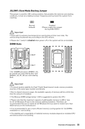
... installed. y Please don't switch to Enabled when power-off or the system will try extreme low temperature overclocking at a stable processor frequency and to prevent the system from crashing. y It is recommended to use a more than the amount of addressable memory is suggested to protect the CPU. Normal (default) Enabled (Please enable this jumper during BIOS POST.) Important y Users will be of Components 33 JSLOW1: Slow Mode Booting Jumper This jumper is used...
... installed. y Please don't switch to Enabled when power-off or the system will try extreme low temperature overclocking at a stable processor frequency and to prevent the system from crashing. y It is recommended to use a more than the amount of addressable memory is suggested to protect the CPU. Normal (default) Enabled (Please enable this jumper during BIOS POST.) Important y Users will be of Components 33 JSLOW1: Slow Mode Booting Jumper This jumper is used...
User Manual
Page 49
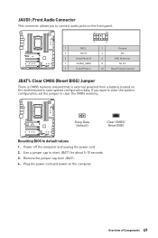
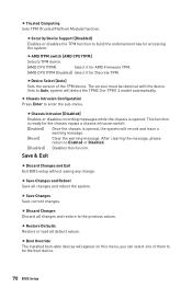
Use a jumper cap to default values 1. Remove the jumper cap from a battery located on the motherboard to save system configuration data. JAUD1: Front Audio Connector This connector allows you want to clear the system configuration, set the jumper to clear the CMOS memory. Power off the computer and unplug the power cord 2. Plug the power cord and power on the front panel. 2 10 1 9 1 MIC L 2 Ground 3 MIC R 4 NC 5 Head Phone R 6 MIC Detection 7 SENSE_SEND 8 No Pin 9 Head Phone L 10...
Use a jumper cap to default values 1. Remove the jumper cap from a battery located on the motherboard to save system configuration data. JAUD1: Front Audio Connector This connector allows you want to clear the system configuration, set the jumper to clear the CMOS memory. Power off the computer and unplug the power cord 2. Plug the power cord and power on the front panel. 2 10 1 9 1 MIC L 2 Ground 3 MIC R 4 NC 5 Head Phone R 6 MIC Detection 7 SENSE_SEND 8 No Pin 9 Head Phone L 10...
User Manual
Page 55
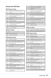
... is started Driver connecting is started PCI Bus initialization is started Pre-memory PCH initialization (PCH module specific) Memory initialization. Serial Presence Detect (SPD) data reading Memory initialization. Configuring memory Memory initialization (other) Memory Installed CPU post-memory initialization is started PCI Bus Hot Plug Controller Initialization Onboard LEDs 55 Cache initialization 34 35 36 37 38 - 3A 3B 3C - 3E 4F CPU post-memory initialization. Boot Strap Processor (BSP) selection CPU post-memory initialization. Debug Code LED Table SEC Progress Codes Power on...
... is started Driver connecting is started PCI Bus initialization is started Pre-memory PCH initialization (PCH module specific) Memory initialization. Serial Presence Detect (SPD) data reading Memory initialization. Configuring memory Memory initialization (other) Memory Installed CPU post-memory initialization is started PCI Bus Hot Plug Controller Initialization Onboard LEDs 55 Cache initialization 34 35 36 37 38 - 3A 3B 3C - 3E 4F CPU post-memory initialization. Boot Strap Processor (BSP) selection CPU post-memory initialization. Debug Code LED Table SEC Progress Codes Power on...
User Manual
Page 56
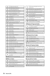
... by user (Forced recovery) Recovery process started A5 SCSI Reset A6 SCSI Detect A7 SCSI Enable A8 Setup Verifying Password A9 Start of Setup AB Setup Input Wait AD Ready To Boot event AE Legacy Boot event AF Exit Boot Services event B0 Runtime Set Virtual Address MAP Begin B1 Runtime Set Virtual Address MAP End B2 Legacy Option ROM Initialization B3 System Reset B4 USB hot plug B5 PCI bus hot plug B6 Clean-up of NVRAM Configuration Reset (reset of...
... by user (Forced recovery) Recovery process started A5 SCSI Reset A6 SCSI Detect A7 SCSI Enable A8 Setup Verifying Password A9 Start of Setup AB Setup Input Wait AD Ready To Boot event AE Legacy Boot event AF Exit Boot Services event B0 Runtime Set Virtual Address MAP Begin B1 Runtime Set Virtual Address MAP End B2 Legacy Option ROM Initialization B3 System Reset B4 USB hot plug B5 PCI bus hot plug B6 Clean-up of NVRAM Configuration Reset (reset of...
User Manual
Page 59
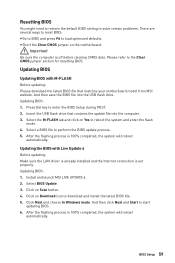
... and enter the flash mode. 4. Updating BIOS: 1. Click on the motherboard. Insert the USB flash drive that matches your motherboard model from MSI website. Install and launch MSI LIVE UPDATE 6. 2. Click on Yes to download and install the latest BIOS file. 5. And then save the BIOS file into the computer. 3. Select BIOS Update. 3. BIOS Setup 59 And then click Next and Start to perform the BIOS update process. 5. y Short the Clear CMOS jumper on Scan button. 4. Click Next and choose In Windows mode. Select a BIOS file to start updating BIOS. 6. Updating BIOS...
... and enter the flash mode. 4. Updating BIOS: 1. Click on the motherboard. Insert the USB flash drive that matches your motherboard model from MSI website. Install and launch MSI LIVE UPDATE 6. 2. Click on Yes to download and install the latest BIOS file. 5. And then save the BIOS file into the computer. 3. Select BIOS Update. 3. BIOS Setup 59 And then click Next and Start to perform the BIOS update process. 5. y Short the Clear CMOS jumper on Scan button. 4. Click Next and choose In Windows mode. Select a BIOS file to start updating BIOS. 6. Updating BIOS...
User Manual
Page 61
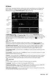
... find the item listing. The boot priority from high to low is left to enable/ disable the A-XMP. To configure the advanced BIOS settings, please enter the Advanced Mode by BIOS item name, enter the item name to switch between software (SW) and hardware (HW) . A-XMP switch Setup Mode switch Screenshot Search Language System information GAME BOOST switch Information display Boot device priority bar M-Flash Favorites Hardware Monitor Function buttons y GAME BOOST switch - Move the mouse...
... find the item listing. The boot priority from high to low is left to enable/ disable the A-XMP. To configure the advanced BIOS settings, please enter the Advanced Mode by BIOS item name, enter the item name to switch between software (SW) and hardware (HW) . A-XMP switch Setup Mode switch Screenshot Search Language System information GAME BOOST switch Information display Boot device priority bar M-Flash Favorites Hardware Monitor Function buttons y GAME BOOST switch - Move the mouse...
User Manual
Page 62
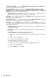
...-used/ favorite BIOS setting items in full speed mode to enter Favorites menu. It allows you can save and access favorite/ frequentlyused BIOS setting items. ƒ Default HomePage - Right-click or press F2 key. 3. Move the mouse over a BIOS item on OK. ƒ To delete a BIOS item from favorite page 1. This feature will increase power consumption. enable or disable the LAN Option ROM, HD audio controller, AHCI/RAID, CPU Fan Fail Warning Control, Windows 10 WHQL support and BIOS Log Review...
...-used/ favorite BIOS setting items in full speed mode to enter Favorites menu. It allows you can save and access favorite/ frequentlyused BIOS setting items. ƒ Default HomePage - Right-click or press F2 key. 3. Move the mouse over a BIOS item on OK. ƒ To delete a BIOS item from favorite page 1. This feature will increase power consumption. enable or disable the LAN Option ROM, HD audio controller, AHCI/RAID, CPU Fan Fail Warning Control, Windows 10 WHQL support and BIOS Log Review...
User Manual
Page 65
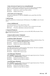
...] Sets UEFI network stack for MSI M.2 XPANDER series cards/ Other M.2 PCIe storage card. BIOS Setup 65 fPCIe SlotX Lanes Configuration PCIe lanes configuration for optimizing IPv4 / IPv6 function. fOnboard LAN Controller/ 2 [Enabled] Enables or disables the onboard LAN controller/ 2. This item will appear when Network Stack is Enabled. [Enabled] Enables the Ipv4 PXE boot support. [Disabled] Disables the Ipv4 PXE boot support. fAbove 4G memory/ Crypto Currency mining [Disabled] Enables or disables 64-bit capable devices to enter the submenu. Press Enter to utilize more...
...] Sets UEFI network stack for MSI M.2 XPANDER series cards/ Other M.2 PCIe storage card. BIOS Setup 65 fPCIe SlotX Lanes Configuration PCIe lanes configuration for optimizing IPv4 / IPv6 function. fOnboard LAN Controller/ 2 [Enabled] Enables or disables the onboard LAN controller/ 2. This item will appear when Network Stack is Enabled. [Enabled] Enables the Ipv4 PXE boot support. [Disabled] Disables the Ipv4 PXE boot support. fAbove 4G memory/ Crypto Currency mining [Disabled] Enables or disables 64-bit capable devices to enter the submenu. Press Enter to utilize more...
User Manual
Page 66
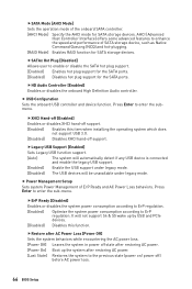
...AC power. [Power On] Boot up by USB and PCIe devices. [Disabled] Disables this item when installing the operating system which does not support USB 3.0. [Disabled] Disables XHCI hand-off ) before AC power loss. 66 BIOS Setup AHCI (Advanced Host Controller Interface) offers some advanced features to the previous state (power on/ power off support. fSATA Mode [AHCI Mode] Sets the operation mode of the onboard SATA controller. [AHCI Mode] Specify the AHCI mode for SATA storage devices. fHD Audio Controller [Enabled] Enables or disables the onboard High Definition Audio controller...
...AC power. [Power On] Boot up by USB and PCIe devices. [Disabled] Disables this item when installing the operating system which does not support USB 3.0. [Disabled] Disables XHCI hand-off ) before AC power loss. 66 BIOS Setup AHCI (Advanced Host Controller Interface) offers some advanced features to the previous state (power on/ power off support. fSATA Mode [AHCI Mode] Sets the operation mode of the onboard SATA controller. [AHCI Mode] Specify the AHCI mode for SATA storage devices. fHD Audio Controller [Enabled] Enables or disables the onboard High Definition Audio controller...
User Manual
Page 67
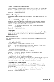
.... [BIOS] Activates the following items, set to [Enabled], the system will appear when Windows 10 WHQL Support is detected. [Disabled] Disables this function. If Resume By RTC Alarm is set wake up events of PCIe device is enabled. fSecure Boot Sets the Windows secure boot to enter the sub-menu. Press Enter to select the date & time settings). fDate (of installed PCI-E expansion cards, integrated LAN controllers or USB devices which are supported by third party integrated chips. [Enabled] Enables the...
.... [BIOS] Activates the following items, set to [Enabled], the system will appear when Windows 10 WHQL Support is detected. [Disabled] Disables this function. If Resume By RTC Alarm is set wake up events of PCIe device is enabled. fSecure Boot Sets the Windows secure boot to enter the sub-menu. Press Enter to select the date & time settings). fDate (of installed PCI-E expansion cards, integrated LAN controllers or USB devices which are supported by third party integrated chips. [Enabled] Enables the...
User Manual
Page 68
... best way to wake the system. f Intel ( R ) I211 Gigabit Network Connection Shows driver information and configuration of the Ethernet controller parameter. f Info Block effect [Unlock] Sets the state of system boot devices. Boot Sets the sequence of Help information block. [Unlock] [Lock] Sliding effect. fResume From S3/S4/S5 by PS/2 Keyboard [Disabled] Enables or disables the system wake up by PS/2 keyboard. [Any Key] Enables the system to...
... best way to wake the system. f Intel ( R ) I211 Gigabit Network Connection Shows driver information and configuration of the Ethernet controller parameter. f Info Block effect [Unlock] Sets the state of system boot devices. Boot Sets the sequence of Help information block. [Unlock] [Lock] Sliding effect. fResume From S3/S4/S5 by PS/2 Keyboard [Disabled] Enables or disables the system wake up by PS/2 keyboard. [Any Key] Enables the system to...
User Manual
Page 70
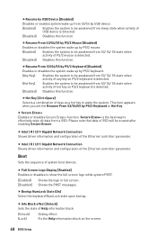
... AMD Firmware TPM. [AMD CPU fTPM Disabled] Select it for the chassis equips a chassis intrusion switch. [Enabled] Once the chassis is opened . fDevice Select [Auto] Sets the version of them to be identical with the device. f Trusted Computing Sets TPM (Trusted Platform Module) function. f Chassis Intrusion Configuration Press Enter to build the endorsement key for accessing the system. This function is opened , the system will record and issue a warning message. [Reset] Clear...
... AMD Firmware TPM. [AMD CPU fTPM Disabled] Select it for the chassis equips a chassis intrusion switch. [Enabled] Once the chassis is opened . fDevice Select [Auto] Sets the version of them to be identical with the device. f Trusted Computing Sets TPM (Trusted Platform Module) function. f Chassis Intrusion Configuration Press Enter to build the endorsement key for accessing the system. This function is opened , the system will record and issue a warning message. [Reset] Clear...
User Manual
Page 71
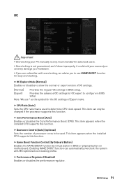
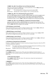
... for easy overclocking. f Downcore Control [Auto] (optional) Sets the number of processor cores to configure in BIOS or physical button on motherboard. f Performance Regulator [Disabled] Enables or disables the performance regulator. Note: We use GAME BOOST function for advanced users. This item can automatically overclock the system with overclocking, we advise you are unfamiliar with MSI optimized overclocking profile. f Game Boost Function Control [By Onboard Button] Enables the GAME BOOST function by virtual button in BIOS setup. Enabling GAME...
... for easy overclocking. f Downcore Control [Auto] (optional) Sets the number of processor cores to configure in BIOS or physical button on motherboard. f Performance Regulator [Disabled] Enables or disables the performance regulator. Note: We use GAME BOOST function for advanced users. This item can automatically overclock the system with overclocking, we advise you are unfamiliar with MSI optimized overclocking profile. f Game Boost Function Control [By Onboard Button] Enables the GAME BOOST function by virtual button in BIOS setup. Enabling GAME...
User Manual
Page 73
... PWM working speed to set it manually. f CPU Memory Changed Detect [Enabled]* Enables or disables the system to issue a warning message during boot when the CPU or memory has been replaced. [Enabled] [Disabled] The system will cause higher temperature of installed memory. The DRAM frequency may be configured automatically by pressing [F4]. If set to Auto, BIOS will set these voltages automatically or you can set to set it manually. f DRAM Voltages control [Auto] These options allows you can also access this settings. Read only. fCPU Technology Support...
... PWM working speed to set it manually. f CPU Memory Changed Detect [Enabled]* Enables or disables the system to issue a warning message during boot when the CPU or memory has been replaced. [Enabled] [Disabled] The system will cause higher temperature of installed memory. The DRAM frequency may be configured automatically by pressing [F4]. If set to Auto, BIOS will set these voltages automatically or you can set to set it manually. f DRAM Voltages control [Auto] These options allows you can also access this settings. Read only. fCPU Technology Support...
User Manual
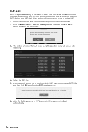
Page 76
... the BIOS update process. 6. Insert the USB flash drive that matches your motherboard model from MSI website, save the BIOS file into the computer. 2. The system will enter the flash mode and a file selection menu will reboot automatically. 76 BIOS Setup Select the BIOS file. 5. And then follow the steps below to update BIOS with a USB flash drive. Click on M-FLASH tab, a demand message will prompt you to toggle the Multi BIOS switch to the target BIOS ROM, and...
... the BIOS update process. 6. Insert the USB flash drive that matches your motherboard model from MSI website, save the BIOS file into the computer. 2. The system will enter the flash mode and a file selection menu will reboot automatically. 76 BIOS Setup Select the BIOS file. 5. And then follow the steps below to update BIOS with a USB flash drive. Click on M-FLASH tab, a demand message will prompt you to toggle the Multi BIOS switch to the target BIOS ROM, and...
User Manual
Page 78
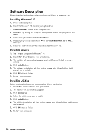
... your optical drive. 3. Follow the instructions on the screen to finish. 7. Installing Drivers 1. The installer will automatically appear and it will prompt you to get into your optical drive from CD or DVD... Click Install button. 5. Click Install button. 6. Press F11 key during the computer POST (Power-On Self Test) to restart. 6. Insert MSI® Driver Disc into Boot Menu. 5. Installing Utilities Before you install utilities, you want to finish. 8. Insert the Windows®...
... your optical drive. 3. Follow the instructions on the screen to finish. 7. Installing Drivers 1. The installer will automatically appear and it will prompt you to get into your optical drive from CD or DVD... Click Install button. 5. Click Install button. 6. Press F11 key during the computer POST (Power-On Self Test) to restart. 6. Insert MSI® Driver Disc into Boot Menu. 5. Installing Utilities Before you install utilities, you want to finish. 8. Insert the Windows®...
User Manual
Page 106
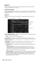
... device. Installation and Update Nahimic 3 is included in one click. displays the type of audio device currently being used as output, as well as you can access all of Nahimic 3's audio effects in the audio driver. allows you need to enter a night mode by removing some basses. Audio Tab From this tab, you wish. Nahimic 3 Nahimic 3 is designed to separately control any of the 5 audio effects. ƒ Surround Sound - y Audio...
... device. Installation and Update Nahimic 3 is included in one click. displays the type of audio device currently being used as output, as well as you can access all of Nahimic 3's audio effects in the audio driver. allows you need to enter a night mode by removing some basses. Audio Tab From this tab, you wish. Nahimic 3 Nahimic 3 is designed to separately control any of the 5 audio effects. ƒ Surround Sound - y Audio...
User Manual
Page 109
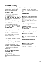
... 1 long 2 short beeps are connected from the power supply to an electrical outlet securely. y Verify if the network cable is properly connected and make sure the button is connected to Keep DATA. y Verify if USB device is no network y Make sure the network chipset driver has been installed. The computer does not boot after updating the BIOS y Clear the CMOS. y Check if the power switch cable is turned on the rear side, make sure the LAN port LEDs are heard, remove...
... 1 long 2 short beeps are connected from the power supply to an electrical outlet securely. y Verify if the network cable is properly connected and make sure the button is connected to Keep DATA. y Verify if USB device is no network y Make sure the network chipset driver has been installed. The computer does not boot after updating the BIOS y Clear the CMOS. y Check if the power switch cable is turned on the rear side, make sure the LAN port LEDs are heard, remove...


