
User Manual
Page 13
...51 JUSB5: USB 3.1 Gen2 Type-C Connector 51 POWER1, RESET1: Power Button, Reset Button 52 JBAT1: Clear CMOS (Reset BIOS) Jumper 52 JCI1: Chassis Intrusion Connector 53 BIOS_SW1: Multi-BIOS Switch 54 JRGB1, JRAINBOW1~2: RGB LED connectors 55 JCORSAIR1: CORSAIR Connector 56 Onboard LEDs ...57 EZ Debug LED...57 DIMM LEDs... ...57 XMP LED ...57 Multi-BIOS LEDs 58 JPWRLED1: LED power input 58 Debug Code LED 59 Hexadecimal Character Table 59 Boot Phases...59 Debug Code LED Table 59 ACPI ...
...51 JUSB5: USB 3.1 Gen2 Type-C Connector 51 POWER1, RESET1: Power Button, Reset Button 52 JBAT1: Clear CMOS (Reset BIOS) Jumper 52 JCI1: Chassis Intrusion Connector 53 BIOS_SW1: Multi-BIOS Switch 54 JRGB1, JRAINBOW1~2: RGB LED connectors 55 JCORSAIR1: CORSAIR Connector 56 Onboard LEDs ...57 EZ Debug LED...57 DIMM LEDs... ...57 XMP LED ...57 Multi-BIOS LEDs 58 JPWRLED1: LED power input 58 Debug Code LED 59 Hexadecimal Character Table 59 Boot Phases...59 Debug Code LED Table 59 ACPI ...

User Manual
Page 14
Settings Tab ...71 BIOS Setup ...72 Entering BIOS Setup 72 Resetting BIOS...73 Updating BIOS...73 EZ Mode ...75 Advanced Mode ...77 SETTINGS...78 Advanced...78 Boot...84 Security ...85 Save & Exit...86 OC...87 M-FLASH ...94 OC PROFILE ...95 ...
Settings Tab ...71 BIOS Setup ...72 Entering BIOS Setup 72 Resetting BIOS...73 Updating BIOS...73 EZ Mode ...75 Advanced Mode ...77 SETTINGS...78 Advanced...78 Boot...84 Security ...85 Save & Exit...86 OC...87 M-FLASH ...94 OC PROFILE ...95 ...

User Manual
Page 16
...PCIe storage devices y Intel® X299 Chipset ƒ 4x USB 3.1 Gen1...Channel High Definition Audio ƒ Supports S/PDIF output Continued on next page Intel® X299 Chipset y Supports RAID 0, RAID1, RAID 5 and RAID 10 for SATA storage devices y... Intel® Optane™ memory modules, please ensure that you have updated the drivers and BIOS to PCIe 3.0 x4, 2242/ 2260/ 2280 storage devices** ƒ Intel® Optane™...bandwidth. Storage RAID USB Audio 16 Specifications Continued from previous page Intel® X299 Chipset y 8x SATA 6Gb/s ports* y 3x M.2 slots (Key M) ƒ...
...PCIe storage devices y Intel® X299 Chipset ƒ 4x USB 3.1 Gen1...Channel High Definition Audio ƒ Supports S/PDIF output Continued on next page Intel® X299 Chipset y Supports RAID 0, RAID1, RAID 5 and RAID 10 for SATA storage devices y... Intel® Optane™ memory modules, please ensure that you have updated the drivers and BIOS to PCIe 3.0 x4, 2242/ 2260/ 2280 storage devices** ƒ Intel® Optane™...bandwidth. Storage RAID USB Audio 16 Specifications Continued from previous page Intel® X299 Chipset y 8x SATA 6Gb/s ports* y 3x M.2 slots (Key M) ƒ...

User Manual
Page 17
Continued from previous page Back Panel Connectors y 1x BIOS FlashBack button y 1x Clear CMOS button y 1x PS/2 keyboard/ mouse combo port y 2x USB 2.0 Type-A ports y 6x USB 3.1 Gen1 Type-A ports y 1x 2.5G LAN (RJ45) ...
Continued from previous page Back Panel Connectors y 1x BIOS FlashBack button y 1x Clear CMOS button y 1x PS/2 keyboard/ mouse combo port y 2x USB 2.0 Type-A ports y 6x USB 3.1 Gen1 Type-A ports y 1x 2.5G LAN (RJ45) ...

User Manual
Page 18
... y 2x 3-pin RAINBOW LED connectors y 1x 3-pin CORSAIR LED connector y 1x OC retry connector y 1x OC force enter BIOS connector y 1x GAME BOOST knob y 1x Power button y 1x Reset button y 1x Multi-BIOS switch y 1x Slow mode jumper y 1x Clear CMOS jumper y 1x 2-Digit Debug Code LED y 4x EZ Debug LED NUVOTON... Chip y CPU/System temperature detection y CPU/System fan speed detection y CPU/System fan speed control y E-ATX Form Factor y 12 in . (30.5 cm x 27.2 cm) y Dual BIOS y 2x 128 Mb flash y UEFI AMI BIOS y ACPI 6.1, SMBIOS 3.0 y Multi-language Continued on next page 18 Specifications
... y 2x 3-pin RAINBOW LED connectors y 1x 3-pin CORSAIR LED connector y 1x OC retry connector y 1x OC force enter BIOS connector y 1x GAME BOOST knob y 1x Power button y 1x Reset button y 1x Multi-BIOS switch y 1x Slow mode jumper y 1x Clear CMOS jumper y 1x 2-Digit Debug Code LED y 4x EZ Debug LED NUVOTON... Chip y CPU/System temperature detection y CPU/System fan speed detection y CPU/System fan speed control y E-ATX Form Factor y 12 in . (30.5 cm x 27.2 cm) y Dual BIOS y 2x 128 Mb flash y UEFI AMI BIOS y ACPI 6.1, SMBIOS 3.0 y Multi-language Continued on next page 18 Specifications

User Manual
Page 20
... USB(3142) ƒ Front Lightning USB(20PIN) y Stability ƒ 7000+ Quality Test y VR ƒ VR Ready y Gamer Experience ƒ GAMING HOTKEY ƒ GAMING MOUSE Control y BIOS ƒ Click BIOS 5 ƒ Flash BIOS Button ƒ Dual BIOS y Certification ƒ Quadro SLI Ready ƒ Quadro Ready ƒ GAMING Certified 20 Specifications
... USB(3142) ƒ Front Lightning USB(20PIN) y Stability ƒ 7000+ Quality Test y VR ƒ VR Ready y Gamer Experience ƒ GAMING HOTKEY ƒ GAMING MOUSE Control y BIOS ƒ Click BIOS 5 ƒ Flash BIOS Button ƒ Dual BIOS y Certification ƒ Quadro SLI Ready ƒ Quadro Ready ƒ GAMING Certified 20 Specifications

User Manual
Page 24
...- Rear I /O Panel Power off your computer. Press and hold the Clear CMOS button for about 5-10 seconds to reset BIOS to page 74 for Updating BIOS with Flash BIOS Button. 2.5G LAN Port LED Status Table Link/ Activity LED Status Off Yellow Blinking Description No link Linked Data activity Speed ... Mbps connection 1 Gbps connection 24 Rear I /O Panel USB 3.1 Gen1 PS/2 Clear CMOS 2.5G LAN WiFi antenna connectors 1G LAN Audio Ports Flash BIOS button USB 2.0 USB 2.0/ Flash BIOS port USB 3.1 Gen2 Type-C USB 3.1 Gen1 Optical S/PDIF-Out USB 3.1 Gen2 Type-A y Clear CMOS button -
...- Rear I /O Panel Power off your computer. Press and hold the Clear CMOS button for about 5-10 seconds to reset BIOS to page 74 for Updating BIOS with Flash BIOS Button. 2.5G LAN Port LED Status Table Link/ Activity LED Status Off Yellow Blinking Description No link Linked Data activity Speed ... Mbps connection 1 Gbps connection 24 Rear I /O Panel USB 3.1 Gen1 PS/2 Clear CMOS 2.5G LAN WiFi antenna connectors 1G LAN Audio Ports Flash BIOS button USB 2.0 USB 2.0/ Flash BIOS port USB 3.1 Gen2 Type-C USB 3.1 Gen1 Optical S/PDIF-Out USB 3.1 Gen2 Type-A y Clear CMOS button -

User Manual
Page 29
...Fan Connectors CPU_PWR1~3, ATX_PWR1, PCIE_PWR1 Power Connectors CPU Socket LGA2066 CPU Socket JAUD1 JBAT1 Front Audio Connector Clear CMOS (Reset BIOS) Jumper JCI1 JCORSAIR1 Chassis Intrusion Connector CORSAIR Connector JFP1, JFP2 JPWRLED1 Front Panel Connectors LED power input JRGB1, JRAINBOW1~2... 3.1 Gen1 Connectors USB 3.1 Gen2 Type-C Connector M2_1~3 OC1 M.2 Slots (Key M) GAME BOOST Knob OC_FS1 OC_RT1 OC Force Enter BIOS Jumper OC Retry Jumper PCI_E1~5 POWER1, RESET1 PCIe Expansion Slots Power Button, Reset Button SATA1~8 T_SEN1 SATA 6Gb/s Connectors Thermal Sensor ...
...Fan Connectors CPU_PWR1~3, ATX_PWR1, PCIE_PWR1 Power Connectors CPU Socket LGA2066 CPU Socket JAUD1 JBAT1 Front Audio Connector Clear CMOS (Reset BIOS) Jumper JCI1 JCORSAIR1 Chassis Intrusion Connector CORSAIR Connector JFP1, JFP2 JPWRLED1 Front Panel Connectors LED power input JRGB1, JRAINBOW1~2... 3.1 Gen1 Connectors USB 3.1 Gen2 Type-C Connector M2_1~3 OC1 M.2 Slots (Key M) GAME BOOST Knob OC_FS1 OC_RT1 OC Force Enter BIOS Jumper OC Retry Jumper PCI_E1~5 POWER1, RESET1 PCIe Expansion Slots Power Button, Reset Button SATA1~8 T_SEN1 SATA 6Gb/s Connectors Thermal Sensor ...
User Manual
Page 44
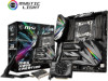
...the computer. 3. Set the GAME BOOST knob to use liquid CPU cooler with MSI DRAGON CENTER software. To disable GAME BOOST: 1. Important y When enabling GAME BOOST mode, it is recommended to HW mode in BIOS Setup. 2. y We do not guarantee the GAME BOOST overclocking range or ...to select the overclocking stage as you to manually select a stage from number 0 (default) to hardware mode in BIOS Setup. 2. y The success of overclocking depends on . y MSI components are recommended for better cooling and performance. y In order to 0 and then power on the components of ...
...the computer. 3. Set the GAME BOOST knob to use liquid CPU cooler with MSI DRAGON CENTER software. To disable GAME BOOST: 1. Important y When enabling GAME BOOST mode, it is recommended to HW mode in BIOS Setup. 2. y We do not guarantee the GAME BOOST overclocking range or ...to select the overclocking stage as you to manually select a stage from number 0 (default) to hardware mode in BIOS Setup. 2. y The success of overclocking depends on . y MSI components are recommended for better cooling and performance. y In order to 0 and then power on the components of ...

User Manual
Page 46
... access to prevent the system from crashing. The overclocking results will try extreme low temperature overclocking at a stable processor frequency and to the BIOS and skip OC failure messages . Normal (default) Enabled (Please enable this jumper, the system will be un-bootable. 46 Overview of ...retrying OC items until it boot up successfully. OC_RT1 Normal (default) OC_FS1 Keep retrying OC Normal (default) Force access to the BIOS and skip OC failure messages JSLOW1: Slow Mode Booting Jumper This jumper is used for LN2 cooling solution, that provides the extreme overclocking...
... access to prevent the system from crashing. The overclocking results will try extreme low temperature overclocking at a stable processor frequency and to the BIOS and skip OC failure messages . Normal (default) Enabled (Please enable this jumper, the system will be un-bootable. 46 Overview of ...retrying OC items until it boot up successfully. OC_RT1 Normal (default) OC_FS1 Keep retrying OC Normal (default) Force access to the BIOS and skip OC failure messages JSLOW1: Slow Mode Booting Jumper This jumper is used for LN2 cooling solution, that provides the extreme overclocking...

User Manual
Page 47
... mode and adjusting fan speed You can switch between PWM mode and DC mode and adjust fan speed in relation to adjust fan speed in BIOS > HARDWARE MONITOR. DC Mode fan connectors control fan speed by changing voltage.
... mode and adjusting fan speed You can switch between PWM mode and DC mode and adjust fan speed in relation to adjust fan speed in BIOS > HARDWARE MONITOR. DC Mode fan connectors control fan speed by changing voltage.

User Manual
Page 49
... Thunderbolt cable to the J1 connector on the motherboard. 4. Use the screw to six Thunderbolt devices Overview of Components 49 Enabling Thunderbolt Technology in the BIOS. 4 USB 3.1 Type-C/ Thunderbolt™ 3 ports DP IN ports J1 connector 2 Thunderbolt cable 1 3 JTBT1 connector Daisy-Chain Thunderbolt drives and DisplayPort monitor Daisy-Chain up to...
... Thunderbolt cable to the J1 connector on the motherboard. 4. Use the screw to six Thunderbolt devices Overview of Components 49 Enabling Thunderbolt Technology in the BIOS. 4 USB 3.1 Type-C/ Thunderbolt™ 3 ports DP IN ports J1 connector 2 Thunderbolt cable 1 3 JTBT1 connector Daisy-Chain Thunderbolt drives and DisplayPort monitor Daisy-Chain up to...

User Manual
Page 52
Keep Data (default) Clear CMOS/ Reset BIOS Resetting BIOS to clear the CMOS memory. If you to short JBAT1 for about 5-10 seconds. 3. Plug the power cord and power on the motherboard to save ... Power / Reset button allows you want to clear the system configuration, set the jumper to default values 1. Power button Reset button JBAT1: Clear CMOS (Reset BIOS) Jumper There is CMOS memory onboard that is external powered from JBAT1. 4.
Keep Data (default) Clear CMOS/ Reset BIOS Resetting BIOS to clear the CMOS memory. If you to short JBAT1 for about 5-10 seconds. 3. Plug the power cord and power on the motherboard to save ... Power / Reset button allows you want to clear the system configuration, set the jumper to default values 1. Power button Reset button JBAT1: Clear CMOS (Reset BIOS) Jumper There is CMOS memory onboard that is external powered from JBAT1. 4.

User Manual
Page 53
...opened again, a warning message will be displayed on screen when the computer is turned on the chassis. 2. Set Chassis Intrusion to BIOS > SETTINGS > Security > Chassis Intrusion Configuration. 2. Resetting the chassis intrusion warning 1. Press F10 to save and exit and then press...the Enter key to select Yes. 6. Go to Reset. 3. Overview of Components 53 JCI1: Chassis Intrusion Connector This connector allows you to BIOS > SETTINGS > Security > Chassis Intrusion Configuration. 4. Go to connect the chassis intrusion switch cable. Close the chassis cover. 3. Normal (...
...opened again, a warning message will be displayed on screen when the computer is turned on the chassis. 2. Set Chassis Intrusion to BIOS > SETTINGS > Security > Chassis Intrusion Configuration. 2. Resetting the chassis intrusion warning 1. Press F10 to save and exit and then press...the Enter key to select Yes. 6. Go to Reset. 3. Overview of Components 53 JCI1: Chassis Intrusion Connector This connector allows you to BIOS > SETTINGS > Security > Chassis Intrusion Configuration. 4. Go to connect the chassis intrusion switch cable. Close the chassis cover. 3. Normal (...
User Manual
Page 54
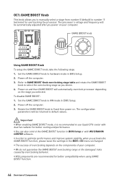
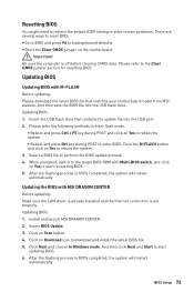
... to the other for details. 54 Overview of the USB flash drive. 1. Before recovering, please download the latest BIOS file that matches your motherboard model from MSI website. After the recovering process is booting up. BIOS A (Default) BIOS B Recovering BIOS When BIOS updating fails or causes the computer non-bootable, you can also use the Multi...
... to the other for details. 54 Overview of the USB flash drive. 1. Before recovering, please download the latest BIOS file that matches your motherboard model from MSI website. After the recovering process is booting up. BIOS A (Default) BIOS B Recovering BIOS When BIOS updating fails or causes the computer non-bootable, you can also use the Multi...

User Manual
Page 58
Multi-BIOS LEDs Multi-BIOS LEDs indicate which BIOS ROM is used by retailers to demonstrate onboard LED light effects. BIOS A LED (Red) BIOS B LED (White) JPWRLED1: LED power input This connector is in operation. JPWRLED1 - LED power input 58 Onboard LEDs
Multi-BIOS LEDs Multi-BIOS LEDs indicate which BIOS ROM is used by retailers to demonstrate onboard LED light effects. BIOS A LED (Red) BIOS B LED (White) JPWRLED1: LED power input This connector is in operation. JPWRLED1 - LED power input 58 Onboard LEDs

User Manual
Page 72
... performance. You could also refer to avoid possible system damage or failure booting unless you are continuously update for reference only. y In MSI Dragon Center application, click on the screen during the boot process. Ctrl+F: Enter Search page * When you purchased. y Press Delete ...key, when the Press DEL key to enter Setup Menu, F11 to enter BIOS setup. BIOS Setup The default settings offer the optimal performance for BIOS item description. y The pictures in normal conditions. Function key F1: General Help F2: Add/ Remove a favorite...
... performance. You could also refer to avoid possible system damage or failure booting unless you are continuously update for reference only. y In MSI Dragon Center application, click on the screen during the boot process. Ctrl+F: Enter Search page * When you purchased. y Press Delete ...key, when the Press DEL key to enter Setup Menu, F11 to enter BIOS setup. BIOS Setup The default settings offer the optimal performance for BIOS item description. y The pictures in normal conditions. Function key F1: General Help F2: Add/ Remove a favorite...
User Manual
Page 73
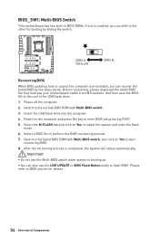
... sure the computer is set properly. Insert the USB flash drive that matches your motherboard model from MSI website. Select a BIOS file to start updating BIOS. 6. Updating the BIOS with MSI DRAGON CENTER Before updating: Make sure the LAN driver is already installed and the Internet connection is ... the flashing process is 100% completed, the system will reboot automatically. Install and launch MSI DRAGON CENTER. 2. And then click Next and Start to reboot the system. 3. Select BIOS Update. 3. And then save the BIOS file into the USB port. 2. Click on Yes to perform the...
... sure the computer is set properly. Insert the USB flash drive that matches your motherboard model from MSI website. Select a BIOS file to start updating BIOS. 6. Updating the BIOS with MSI DRAGON CENTER Before updating: Make sure the LAN driver is already installed and the Internet connection is ... the flashing process is 100% completed, the system will reboot automatically. Install and launch MSI DRAGON CENTER. 2. And then click Next and Start to reboot the system. 3. Select BIOS Update. 3. And then save the BIOS file into the USB port. 2. Click on Yes to perform the...

User Manual
Page 74
... process is completed. To check your motherboard model from the MSI® website. 2. Connect the power supply to CPU_PWR1 and ATX_PWR1. (No need to Properties. 74 BIOS Setup Please download the latest BIOS file that contains the MSI.ROM file into the Flash BIOS Port on the drive icon and go to Windows Explorer, right...
... process is completed. To check your motherboard model from the MSI® website. 2. Connect the power supply to CPU_PWR1 and ATX_PWR1. (No need to Properties. 74 BIOS Setup Please download the latest BIOS file that contains the MSI.ROM file into the Flash BIOS Port on the drive icon and go to Windows Explorer, right...

User Manual
Page 75
... at rightbottom corner. supported memory module is left to right. y Setup Mode switch - It allows you to exit search page. y Language - BIOS Setup 75 This switch will show. y Screenshot - shows the CPU/ DDR speed, CPU/ MB temperature, MB/ CPU type, memory size, CPU/ DDR ... to enable/ disable the X.M.P. (Extreme Memory Profile). Move the mouse over a blank space and right click the mouse to select the language of BIOS setup. Important In search page, only the F6, F10 and F12 function keys are available. y Search - allows you to search by pressing the...
... at rightbottom corner. supported memory module is left to right. y Setup Mode switch - It allows you to exit search page. y Language - BIOS Setup 75 This switch will show. y Screenshot - shows the CPU/ DDR speed, CPU/ MB temperature, MB/ CPU type, memory size, CPU/ DDR ... to enable/ disable the X.M.P. (Extreme Memory Profile). Move the mouse over a blank space and right click the mouse to select the language of BIOS setup. Important In search page, only the F6, F10 and F12 function keys are available. y Search - allows you to search by pressing the...


