
User Manual
Page 13
...: CORSAIR Connector 56 Onboard LEDs ...57 EZ Debug LED...57 DIMM LEDs ...57 XMP LED ...57 Multi-BIOS LEDs 58 JPWRLED1: LED power input 58 Debug Code LED 59 Hexadecimal Character Table 59 Boot Phases...59 Debug Code LED Table 59 ACPI States Codes 64 CPU Temperature 64 Installing OS, Drivers & Utilities 65 Installing Windows® 10 65 Installing Drivers 65 Installing Utilities 65 MYSTIC LIGHT...66 Device LED effect control screen 66 Nahimic 3 ...69 Installation and Update 69 Audio Tab ...69 Microphone Tab ...70 Sound Tracker...
...: CORSAIR Connector 56 Onboard LEDs ...57 EZ Debug LED...57 DIMM LEDs ...57 XMP LED ...57 Multi-BIOS LEDs 58 JPWRLED1: LED power input 58 Debug Code LED 59 Hexadecimal Character Table 59 Boot Phases...59 Debug Code LED Table 59 ACPI States Codes 64 CPU Temperature 64 Installing OS, Drivers & Utilities 65 Installing Windows® 10 65 Installing Drivers 65 Installing Utilities 65 MYSTIC LIGHT...66 Device LED effect control screen 66 Nahimic 3 ...69 Installation and Update 69 Audio Tab ...69 Microphone Tab ...70 Sound Tracker...

User Manual
Page 24
... default values. Power off your computer. y Flash BIOS Button/Port - Rear I /O Panel Press and hold the Clear CMOS button for about 5-10 seconds to reset BIOS to page 74 for Updating BIOS with Flash BIOS Button. 2.5G LAN Port LED Status Table Link/ Activity LED Status Off Yellow Blinking Description No link Linked Data activity Speed LED Status Off Green Orange Description 10 Mbps connection 1 Gbps/ 100 Mbps connection 2.5 Gbps connection 1G LAN Port LED Status Table Link/ Activity LED...
... default values. Power off your computer. y Flash BIOS Button/Port - Rear I /O Panel Press and hold the Clear CMOS button for about 5-10 seconds to reset BIOS to page 74 for Updating BIOS with Flash BIOS Button. 2.5G LAN Port LED Status Table Link/ Activity LED Status Off Yellow Blinking Description No link Linked Data activity Speed LED Status Off Green Orange Description 10 Mbps connection 1 Gbps/ 100 Mbps connection 2.5 Gbps connection 1G LAN Port LED Status Table Link/ Activity LED...

User Manual
Page 60
... memory speed 51 Memory initialization error. SPD reading has failed 52 Memory initialization error. Boot Strap Processor (BSP) selection CPU post-memory initialization. No usable memory detected 54 Unspecified memory initialization error 55 Memory not installed 60 Onboard LEDs Configuring memory Memory initialization (other) Memory Installed CPU post-memory initialization is started Pre-memory PCH initialization (PCH module specific) Memory initialization. SEC Error Codes 0C - 0D 0E 0F Reserved for future AMI SEC error codes Microcode not found Microcode not loaded...
... memory speed 51 Memory initialization error. SPD reading has failed 52 Memory initialization error. Boot Strap Processor (BSP) selection CPU post-memory initialization. No usable memory detected 54 Unspecified memory initialization error 55 Memory not installed 60 Onboard LEDs Configuring memory Memory initialization (other) Memory Installed CPU post-memory initialization is started Pre-memory PCH initialization (PCH module specific) Memory initialization. SEC Error Codes 0C - 0D 0E 0F Reserved for future AMI SEC error codes Microcode not found Microcode not loaded...
User Manual
Page 61
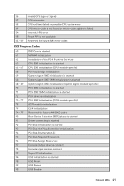
... is started PCH DXE SMM initialization is started PCH devices initialization PCH DXE Initialization (PCH module specific) ACPI module initialization CSM initialization Reserved for future AMI DXE codes Boot Device Selection (BDS) phase is started Driver connecting is started PCI Bus initialization is started PCI Bus Hot Plug Controller Initialization PCI Bus Enumeration 32 PCI Bus Request Resources PCI Bus Assign Resources Console Output devices connect Console input devices connect Super IO Initialization USB initialization is started USB Reset USB Detect USB Enable Onboard LEDs 61
... is started PCH DXE SMM initialization is started PCH devices initialization PCH DXE Initialization (PCH module specific) ACPI module initialization CSM initialization Reserved for future AMI DXE codes Boot Device Selection (BDS) phase is started Driver connecting is started PCI Bus initialization is started PCI Bus Hot Plug Controller Initialization PCI Bus Enumeration 32 PCI Bus Request Resources PCI Bus Assign Resources Console Output devices connect Console input devices connect Super IO Initialization USB initialization is started USB Reset USB Detect USB Enable Onboard LEDs 61
User Manual
Page 62
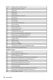
... Boot Option is failed (StartImage returned error) DB Flash update is started SCSI Reset SCSI Detect SCSI Enable Setup Verifying Password Start of Setup Setup Input Wait Ready To Boot event Legacy Boot event Exit Boot Services event Runtime Set Virtual Address MAP Begin Runtime Set Virtual Address MAP End Legacy Option ROM Initialization System Reset USB hot plug PCI bus hot plug Clean-up of NVRAM Configuration Reset (reset of NVRAM settings) Reserved for future AMI codes IDE initialization is started IDE Reset IDE Detect IDE Enable SCSI initialization is failed 62 Onboard LEDs...
... Boot Option is failed (StartImage returned error) DB Flash update is started SCSI Reset SCSI Detect SCSI Enable Setup Verifying Password Start of Setup Setup Input Wait Ready To Boot event Legacy Boot event Exit Boot Services event Runtime Set Virtual Address MAP Begin Runtime Set Virtual Address MAP End Legacy Option ROM Initialization System Reset USB hot plug PCI bus hot plug Clean-up of NVRAM Configuration Reset (reset of NVRAM settings) Reserved for future AMI codes IDE initialization is started IDE Reset IDE Detect IDE Enable SCSI initialization is failed 62 Onboard LEDs...

User Manual
Page 65
... screen shows Press any key to finish. 8. Start up notification, then select Run DVDSetup.exe to finish. 7. If you turn off the AutoPlay feature from the Boot Menu. 6. Restart your computer. 3. Open the installer as described above. 2. Select the Windows® 10 installation disc/USB from the Windows Control Panel, you must complete drivers installation. 1. Click OK button to open the installer. Power on the computer case. 4. Installing OS, Drivers & Utilities Please download...
... screen shows Press any key to finish. 8. Start up notification, then select Run DVDSetup.exe to finish. 7. If you turn off the AutoPlay feature from the Boot Menu. 6. Restart your computer. 3. Open the installer as described above. 2. Select the Windows® 10 installation disc/USB from the Windows Control Panel, you must complete drivers installation. 1. Click OK button to open the installer. Power on the computer case. 4. Installing OS, Drivers & Utilities Please download...
User Manual
Page 69
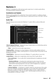
... 3's audio effects, audio profiles and settings. All profiles can access all sound softer, balanced or louder. y Audio Effects - Audio Tab From this tab, you to separately control any of Nahimic 3's audio effects in the audio driver. Nahimic 3 69 allows you can be modified as its current volume. ƒ Mute - virtualizes the multichannel audio stream from MSI's official website. If you 're using speakers to enter a night mode by removing...
... 3's audio effects, audio profiles and settings. All profiles can access all sound softer, balanced or louder. y Audio Effects - Audio Tab From this tab, you to separately control any of Nahimic 3's audio effects in the audio driver. Nahimic 3 69 allows you can be modified as its current volume. ƒ Mute - virtualizes the multichannel audio stream from MSI's official website. If you 're using speakers to enter a night mode by removing...
User Manual
Page 73
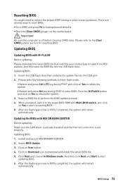
... M-FLASH button and click on Download icon to reboot the system. 3. Install and launch MSI DRAGON CENTER. 2. Updating BIOS: 1. Insert the USB flash drive that matches your motherboard model from MSI website. Select BIOS Update. 3. Click Next and choose In Windows mode. Important Be sure the computer is 100% completed, the system will reboot automatically. Select a BIOS file to the Clear CMOS jumper section for resetting BIOS. Resetting BIOS You might need to restore the default BIOS setting to...
... M-FLASH button and click on Download icon to reboot the system. 3. Install and launch MSI DRAGON CENTER. 2. Updating BIOS: 1. Insert the USB flash drive that matches your motherboard model from MSI website. Select BIOS Update. 3. Click Next and choose In Windows mode. Important Be sure the computer is 100% completed, the system will reboot automatically. Select a BIOS file to the Clear CMOS jumper section for resetting BIOS. Resetting BIOS You might need to restore the default BIOS setting to...

User Manual
Page 74
... format USB flash drive supports updating BIOS by Flash BIOS Button. Plug the USB flash drive that matches your motherboard model from the MSI® website. 2. To check your USB flash drive (FAT32 format). 3. Press the Flash BIOS Button to install CPU and memory.) 4. Updating BIOS with Flash BIOS Button 1. Rename the BIOS file to MSI.ROM, and save it to the root of your drive, go to Windows Explorer, right click on the rear I/O panel. 5. Connect the power supply to CPU_PWR1 and ATX_PWR1. (No need to flash BIOS, and the LED starts flashing. 6. Please download...
... format USB flash drive supports updating BIOS by Flash BIOS Button. Plug the USB flash drive that matches your motherboard model from the MSI® website. 2. To check your USB flash drive (FAT32 format). 3. Press the Flash BIOS Button to install CPU and memory.) 4. Updating BIOS with Flash BIOS Button 1. Rename the BIOS file to MSI.ROM, and save it to the root of your drive, go to Windows Explorer, right click on the rear I/O panel. 5. Connect the power supply to CPU_PWR1 and ATX_PWR1. (No need to flash BIOS, and the LED starts flashing. 6. Please download...

User Manual
Page 75
... display Boot device priority bar M-Flash Favorites Hardware Monitor Function buttons y GAME BOOST switch - Switch the outer circle to USB flash drive (FAT/ FAT32 format only). click on the inner circle to exit search page. y Boot device priority bar - y Setup Mode switch - shows the CPU/ DDR speed, CPU/ MB temperature, MB/ CPU type, memory size, CPU/ DDR voltage, BIOS version and build date. profile. y Search - you to switch between software (SW) and hardware (HW) . The boot priority from high to low is installed...
... display Boot device priority bar M-Flash Favorites Hardware Monitor Function buttons y GAME BOOST switch - Switch the outer circle to USB flash drive (FAT/ FAT32 format only). click on the inner circle to exit search page. y Boot device priority bar - y Setup Mode switch - shows the CPU/ DDR speed, CPU/ MB temperature, MB/ CPU type, memory size, CPU/ DDR voltage, BIOS version and build date. profile. y Search - you to switch between software (SW) and hardware (HW) . The boot priority from high to low is installed...

User Manual
Page 76
...; Default HomePage - Right-click or press F2 key. 3. Right-click or press F2 key. 3. press the Favorites tab or the F3 key to select a BIOS menu (e.g. Choose a favorite page and click on OK. 76 BIOS Setup Choose Delete and click on OK. ƒ To delete a BIOS item from favorite page 1. enable or disable the LAN Option ROM, M.2/Optane Genie, HD audio controller, AHCI, RAID, CPU Fan Fail Warning Control and BIOS Log Review...
...; Default HomePage - Right-click or press F2 key. 3. Right-click or press F2 key. 3. press the Favorites tab or the F3 key to select a BIOS menu (e.g. Choose a favorite page and click on OK. 76 BIOS Setup Choose Delete and click on OK. ƒ To delete a BIOS item from favorite page 1. enable or disable the LAN Option ROM, M.2/Optane Genie, HD audio controller, AHCI, RAID, CPU Fan Fail Warning Control and BIOS Log Review...

User Manual
Page 79
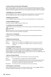
...The power LED blinks to utilize more than 4x GPUs. [Disabled] Disables this function. Press Enter to enter the submenu. fLAN Option ROM [Disabled] Enables or disables the legacy network Boot Option ROM for matching different installed devices. [Auto] This item will appear when Onboard LAN Controller is over 80 degrees centigrade. Max Link Speed [Auto] Sets PCI Express protocol of PCIe x16 slots for detailed settings. f Integrated Peripherals Sets integrated peripherals' parameters, such as LAN, HDD, USB and audio. fOnboard LAN Controller2 [Enabled] Enables or disables the...
...The power LED blinks to utilize more than 4x GPUs. [Disabled] Disables this function. Press Enter to enter the submenu. fLAN Option ROM [Disabled] Enables or disables the legacy network Boot Option ROM for matching different installed devices. [Auto] This item will appear when Onboard LAN Controller is over 80 degrees centigrade. Max Link Speed [Auto] Sets PCI Express protocol of PCIe x16 slots for detailed settings. f Integrated Peripherals Sets integrated peripherals' parameters, such as LAN, HDD, USB and audio. fOnboard LAN Controller2 [Enabled] Enables or disables the...

User Manual
Page 80
...] Specify the AHCI mode for SATA storage devices. fHD Audio Controller [Enabled] Enables or disables the onboard High Definition Audio controller. This item will appear when Network Stack is enabled. [Enabled] Enables the Ipv4 PXE boot support. [Disabled] Disables the Ipv4 PXE boot support. fM.2/Optane Genie [Disabled] Enables or disables M.2 storage/ Optane memory. fSATAx Hot Plug [Disabled] Allows user to enter the submenu. f USB Configuration Sets the onboard USB controller and device function. fUSB Controller [Enabled] Enables or disables all USB controller. 80 BIOS Setup...
...] Specify the AHCI mode for SATA storage devices. fHD Audio Controller [Enabled] Enables or disables the onboard High Definition Audio controller. This item will appear when Network Stack is enabled. [Enabled] Enables the Ipv4 PXE boot support. [Disabled] Disables the Ipv4 PXE boot support. fM.2/Optane Genie [Disabled] Enables or disables M.2 storage/ Optane memory. fSATAx Hot Plug [Disabled] Allows user to enter the submenu. f USB Configuration Sets the onboard USB controller and device function. fUSB Controller [Enabled] Enables or disables all USB controller. 80 BIOS Setup...

User Manual
Page 81
... sure all installed devices & utilities (hardware & software) should meet the Windows equirement. [Disabled] Disables this function. fLegacy USB Support [Enabled] Sets Legacy USB function support. [Auto] The system will automatically detect if any USB device is connected and enable the legacy USB support. [Enabled] Enable the USB support under legacy mode. [Disabled] The USB devices will not support S4 & S5 wake up the system after restoring AC power. [Last State] Restores the system to enter the sub-menu. Press Enter to the previous state (power on/ power off state...
... sure all installed devices & utilities (hardware & software) should meet the Windows equirement. [Disabled] Disables this function. fLegacy USB Support [Enabled] Sets Legacy USB function support. [Auto] The system will automatically detect if any USB device is connected and enable the legacy USB support. [Enabled] Enable the USB support under legacy mode. [Disabled] The USB devices will not support S4 & S5 wake up the system after restoring AC power. [Last State] Restores the system to enter the sub-menu. Press Enter to the previous state (power on/ power off state...

User Manual
Page 88
... motherboard. This item appears when the installed CPU supports this function. You may overclock the CPU by virtual button in BIOS or physical button on the installed CPU. f CPU Base Clock Apply Mode [Auto]* Sets the applying mode for adjusted CPU base clock. [Auto] This setting will be configured automatically by BIOS. [Enabled] All CPU cores would be helpful for all CPU cores to boost CPU performance automatically above rated specifications when system request the highest performance state. [Disabled] Disables this function. [Auto] This setting...
... motherboard. This item appears when the installed CPU supports this function. You may overclock the CPU by virtual button in BIOS or physical button on the installed CPU. f CPU Base Clock Apply Mode [Auto]* Sets the applying mode for adjusted CPU base clock. [Auto] This setting will be configured automatically by BIOS. [Enabled] All CPU cores would be helpful for all CPU cores to boost CPU performance automatically above rated specifications when system request the highest performance state. [Disabled] Disables this function. [Auto] This setting...
User Manual
Page 90
... changing memory timing. Please note the overclocking behavior is not guaranteed. User can set it occurs, please clear the CMOS data and restore the default settings. (Refer to the Clear CMOS jumper/ button section to clear the CMOS data, and enter the BIOS to load the default settings.) f Memory Fast Boot [Auto]* Enables or disables the initiation and training for memory every booting. [Auto] [Enabled] [Disabled] The setting will set these voltages automatically or you to CPU. This item appears when a CPU that support X.M.P. f CPU Voltages control [Auto] These options...
... changing memory timing. Please note the overclocking behavior is not guaranteed. User can set it occurs, please clear the CMOS data and restore the default settings. (Refer to the Clear CMOS jumper/ button section to clear the CMOS data, and enter the BIOS to load the default settings.) f Memory Fast Boot [Auto]* Enables or disables the initiation and training for memory every booting. [Auto] [Enabled] [Disabled] The setting will set these voltages automatically or you to CPU. This item appears when a CPU that support X.M.P. f CPU Voltages control [Auto] These options...
User Manual
Page 92
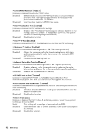
...] Disable this function. 92 BIOS Setup fIntel C-State [Auto] Enables or disables the Intel C-state. fHardware Prefetcher [Enabled] Enables or disables the hardware prefetcher (MLC Streamer prefetcher). [Enabled] Allows the hardware prefetcher to the specific application. [Disabled] Enables the requested cache line only. fCPU AES Instructions [Enabled] Enables or disables the CPU AES (Advanced Encryption Standard-New Instructions) support. fIntel Adaptive Thermal Monitor [Enabled] Enables or disables the Intel adaptive thermal monitor function to circumvent boot problems...
...] Disable this function. 92 BIOS Setup fIntel C-State [Auto] Enables or disables the Intel C-state. fHardware Prefetcher [Enabled] Enables or disables the hardware prefetcher (MLC Streamer prefetcher). [Enabled] Allows the hardware prefetcher to the specific application. [Disabled] Enables the requested cache line only. fCPU AES Instructions [Enabled] Enables or disables the CPU AES (Advanced Encryption Standard-New Instructions) support. fIntel Adaptive Thermal Monitor [Enabled] Enables or disables the Intel adaptive thermal monitor function to circumvent boot problems...
User Manual
Page 102
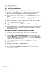
... the disk/ USB drive in BIOS. 2. Insert the MSI Driver Disc into the optical drive. Under the Drivers/Software tab, check the Intel RAID Drivers check-box. 5. When prompt you can still manually execute the DVDSetup.exe from the root path of the drivers while installing Windows 10 x64 bit Editions or newer operating system. 1. Insert the MSI Driver Disc into the optical drive. 3. As previously mentioned, enable Intel(R) Rapid Storage Technology...
... the disk/ USB drive in BIOS. 2. Insert the MSI Driver Disc into the optical drive. Under the Drivers/Software tab, check the Intel RAID Drivers check-box. 5. When prompt you can still manually execute the DVDSetup.exe from the root path of the drivers while installing Windows 10 x64 bit Editions or newer operating system. 1. Insert the MSI Driver Disc into the optical drive. 3. As previously mentioned, enable Intel(R) Rapid Storage Technology...
User Manual
Page 103
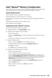
i Processor y System BIOS that supports the Intel® Rapid Storage Technology (Intel® RST) 16 or later driver y Operating system: Windows 10 64 bit (UEFI mode). Update BIOS (refer to install and remove the Intel® Optane™ memory. If you to restart, click OK button to finish. ˜ Reboot System. This section describes how to the Updating BIOS section). 2. System Requirements y Intel® Optane™ memory ready MSI® motherboards y Supported 8th...
i Processor y System BIOS that supports the Intel® Rapid Storage Technology (Intel® RST) 16 or later driver y Operating system: Windows 10 64 bit (UEFI mode). Update BIOS (refer to install and remove the Intel® Optane™ memory. If you to restart, click OK button to finish. ˜ Reboot System. This section describes how to the Updating BIOS section). 2. System Requirements y Intel® Optane™ memory ready MSI® motherboards y Supported 8th...

User Manual
Page 106
y Connect the AC power cord to JFP1 pin header properly. y Check if the power switch cable is connected to an electrical outlet securely. y Make sure the monitor is not working graphics card. y Test with another known working LAN cable. There is no network y Make sure the network chipset driver has been installed. The USB device is turned on the motherboard rear IO panel. y Use the secondary BIOS to install only one memory module in the DIMMC1 slot first and then restart...
y Connect the AC power cord to JFP1 pin header properly. y Check if the power switch cable is connected to an electrical outlet securely. y Make sure the monitor is not working graphics card. y Test with another known working LAN cable. There is no network y Make sure the network chipset driver has been installed. The USB device is turned on the motherboard rear IO panel. y Use the secondary BIOS to install only one memory module in the DIMMC1 slot first and then restart...


