
User Manual
Page 12
... 3.2 Gen 1 Type-C Connector 35 JUSB3: USB 3.2 Gen 1 Connector 36 JTBT1: Thunderbolt Add-on Card Connector 37 JRTD3: Intel RTD3 Connector 37 JBAT1: Clear CMOS (Reset BIOS) Jumper 38 JTPM1: TPM Module Connector 38 JCI1: Chassis Intrusion Connector 39 12 Contents
... 3.2 Gen 1 Type-C Connector 35 JUSB3: USB 3.2 Gen 1 Connector 36 JTBT1: Thunderbolt Add-on Card Connector 37 JRTD3: Intel RTD3 Connector 37 JBAT1: Clear CMOS (Reset BIOS) Jumper 38 JTPM1: TPM Module Connector 38 JCI1: Chassis Intrusion Connector 39 12 Contents

User Manual
Page 13
... LED Control 42 Installing OS, Drivers & Utilities 43 Installing Windows® 10 43 Installing Drivers 43 Installing Utilities 43 UEFI BIOS...44 BIOS Setup...45 Entering BIOS Setup 45 Resetting BIOS...46 Updating BIOS...46 EZ Mode...48 Advanced Mode ...52 SETTINGS Menu...53 OC Menu...55 M-FLASH Menu...59 OC PROFILE Menu 60 HARDWARE...
... LED Control 42 Installing OS, Drivers & Utilities 43 Installing Windows® 10 43 Installing Drivers 43 Installing Utilities 43 UEFI BIOS...44 BIOS Setup...45 Entering BIOS Setup 45 Resetting BIOS...46 Updating BIOS...46 EZ Mode...48 Advanced Mode ...52 SETTINGS Menu...53 OC Menu...55 M-FLASH Menu...59 OC PROFILE Menu 60 HARDWARE...

User Manual
Page 14
...30Hz ∙∙1x DisplayPort port supports a maximum resolution of 4096 x 2304 @ 60Hz ∙∙Supports AMD® 2-Way CrossFire™ Technology Intel® Z490 Chipset ∙∙6x SATA 6Gb/s ports* ∙∙2x M.2 slots (Key M) ▪▪Supports up to PCIe 3.0 x4 and SATA 6Gb/s &#...® Optane™ memory modules, please ensure that you have updated the drivers and BIOS to intel.com for LGA 1200 socket* * Please go to the latest version from MSI website. Intel® Z490 Chipset ∙∙4x DDR4 memory slots, support up to 128GB* ∙∙Supports...
...30Hz ∙∙1x DisplayPort port supports a maximum resolution of 4096 x 2304 @ 60Hz ∙∙Supports AMD® 2-Way CrossFire™ Technology Intel® Z490 Chipset ∙∙6x SATA 6Gb/s ports* ∙∙2x M.2 slots (Key M) ▪▪Supports up to PCIe 3.0 x4 and SATA 6Gb/s &#...® Optane™ memory modules, please ensure that you have updated the drivers and BIOS to intel.com for LGA 1200 socket* * Please go to the latest version from MSI website. Intel® Z490 Chipset ∙∙4x DDR4 memory slots, support up to 128GB* ∙∙Supports...

User Manual
Page 16
x 9.6 in . Continued from previous page Internal Connectors LED Features I/O Controller Hardware Monitor Form Factor BIOS Features ∙∙1x 24-pin ATX main power connector ∙∙1x 8-pin ATX 12V power connector ∙∙1x 4-pin ATX 12V power ... speed control ∙∙ATX Form Factor ∙∙12 in . (30.5 cm x 24.4 cm) ∙∙1x 256 Mb flash ∙∙UEFI AMI BIOS ∙∙ACPI 6.2, SM BIOS 3.2 ∙∙ Multi-language Continued on next page 16 Specifications
x 9.6 in . Continued from previous page Internal Connectors LED Features I/O Controller Hardware Monitor Form Factor BIOS Features ∙∙1x 24-pin ATX main power connector ∙∙1x 8-pin ATX 12V power connector ∙∙1x 4-pin ATX 12V power ... speed control ∙∙ATX Form Factor ∙∙12 in . (30.5 cm x 24.4 cm) ∙∙1x 256 Mb flash ∙∙UEFI AMI BIOS ∙∙ACPI 6.2, SM BIOS 3.2 ∙∙ Multi-language Continued on next page 16 Specifications

User Manual
Page 18
... ▪▪USB with type A+C ▪▪Front USB Type-C ▪▪Dual CPU Power ∙∙ Experience ▪▪DRAGON CENTER ▪▪Click BIOS 5 18 Specifications
... ▪▪USB with type A+C ▪▪Front USB Type-C ▪▪Dual CPU Power ∙∙ Experience ▪▪DRAGON CENTER ▪▪Click BIOS 5 18 Specifications

User Manual
Page 25
..., SYS_FAN1~6 Fan Connectors CPU_PWR1, ATX_PWR1 Power Connectors CPU Socket LGA 1200 CPU Socket DIMM Slots Memory slots JAUD1 Front Audio Connector JBAT1 Clear CMOS (Reset BIOS) Jumper JCI1 Chassis Intrusion Connector JFP1, JFP2 Front Panel Connectors JRAINBOW1~2 Addressable RGB LED connectors JRGB1~2 RGB LED connectors JRTD3 Intel RTD3 Connector JTBT1 Thunderbolt...
..., SYS_FAN1~6 Fan Connectors CPU_PWR1, ATX_PWR1 Power Connectors CPU Socket LGA 1200 CPU Socket DIMM Slots Memory slots JAUD1 Front Audio Connector JBAT1 Clear CMOS (Reset BIOS) Jumper JCI1 Chassis Intrusion Connector JFP1, JFP2 Front Panel Connectors JRAINBOW1~2 Addressable RGB LED connectors JRGB1~2 RGB LED connectors JRTD3 Intel RTD3 Connector JTBT1 Thunderbolt...

User Manual
Page 27
Go to BIOS and find the DRAM Frequency to set the memory frequency if you want to operate the memory at the marked or at a lower frequency than ... information on its Serial Presence Detect (SPD). Overview of installed memory module depend on installed CPU and devices when overclocking. ∙∙Please refer www.msi.com for full DIMMs installation or overclocking. ∙∙The stability and compatibility of Components 27 DIMM Slots DIMMA1 DIMMB1 Channel A Channel B DIMMA2 Memory module...
Go to BIOS and find the DRAM Frequency to set the memory frequency if you want to operate the memory at the marked or at a lower frequency than ... information on its Serial Presence Detect (SPD). Overview of installed memory module depend on installed CPU and devices when overclocking. ∙∙Please refer www.msi.com for full DIMMs installation or overclocking. ∙∙The stability and compatibility of Components 27 DIMM Slots DIMMA1 DIMMB1 Channel A Channel B DIMMA2 Memory module...

User Manual
Page 34
... Control Signal DC Mode pin definition 1 Ground 2 Voltage Control 3 Sense 4 NC 34 Overview of the fan speed that allow you to adjust fan speed in BIOS > HARDWARE MONITOR. DC Mode fan connectors control fan speed by changing voltage. Select PWM mode or DC mode There are working properly after switching the...
... Control Signal DC Mode pin definition 1 Ground 2 Voltage Control 3 Sense 4 NC 34 Overview of the fan speed that allow you to adjust fan speed in BIOS > HARDWARE MONITOR. DC Mode fan connectors control fan speed by changing voltage. Select PWM mode or DC mode There are working properly after switching the...

User Manual
Page 38
JBAT1: Clear CMOS (Reset BIOS) Jumper There is CMOS memory onboard that is for TPM (Trusted Platform Module). Remove the jumper cap from a battery located on the computer. Use a jumper ... unplug the power cord 2. If you want to clear the system configuration, set the jumper to default values 1. Keep Data (default) Clear CMOS/ Reset BIOS Resetting BIOS to clear the CMOS memory. JTPM1: TPM Module Connector This connector is external powered from JBAT1. 4. Plug the power cord and power on the motherboard...
JBAT1: Clear CMOS (Reset BIOS) Jumper There is CMOS memory onboard that is for TPM (Trusted Platform Module). Remove the jumper cap from a battery located on the computer. Use a jumper ... unplug the power cord 2. If you want to clear the system configuration, set the jumper to default values 1. Keep Data (default) Clear CMOS/ Reset BIOS Resetting BIOS to clear the CMOS memory. JTPM1: TPM Module Connector This connector is external powered from JBAT1. 4. Plug the power cord and power on the motherboard...

User Manual
Page 39
... save and exit and then press the Enter key to select Yes. Go to the chassis intrusion switch/ sensor on . Connect the JCI1 connector to BIOS > SETTINGS > Security > Chassis Intrusion Configuration. 2. Go to Enabled. 5. Resetting the chassis intrusion warning 1. Overview of Components 39 Set Chassis Intrusion to...
... save and exit and then press the Enter key to select Yes. Go to the chassis intrusion switch/ sensor on . Connect the JCI1 connector to BIOS > SETTINGS > Security > Chassis Intrusion Configuration. 2. Go to Enabled. 5. Resetting the chassis intrusion warning 1. Overview of Components 39 Set Chassis Intrusion to...

User Manual
Page 44
...only 64-bit Windows 10 operating system. ∙∙ Older graphics card - And also eliminates the time to switch to check the BIOS mode? When display a warning message There is compatible with UEFI (Unified Extensible Firmware Interface) architecture. UEFI advantages ∙∙Fast ... directly boot the operating system and save the BIOS selftest process. After entering the BIOS, find the BIOS Mode at the top of new devices - Incompatible UEFI cases ∙∙ 32-bit Windows operating system - UEFI BIOS MSI UEFI BIOS is no malware tampers with the startup process...
...only 64-bit Windows 10 operating system. ∙∙ Older graphics card - And also eliminates the time to switch to check the BIOS mode? When display a warning message There is compatible with UEFI (Unified Extensible Firmware Interface) architecture. UEFI advantages ∙∙Fast ... directly boot the operating system and save the BIOS selftest process. After entering the BIOS, find the BIOS Mode at the top of new devices - Incompatible UEFI cases ∙∙ 32-bit Windows operating system - UEFI BIOS MSI UEFI BIOS is no malware tampers with the startup process...

User Manual
Page 45
... defaults F7: Switch between Yes or No to the HELP information panel for reference only and may be for reference only. BIOS Setup The default settings offer the optimal performance for system stability in this chapter are continuously update for better system performance. You...Ctrl+F: Enter Search page * When you purchased. ∙∙The BIOS items will vary with BIOS. ⚠⚠Important ∙∙BIOS items are for BIOS item description. ∙∙The pictures in normal conditions. UEFI BIOS 45 You should be slightly different from the product you press F10,...
... defaults F7: Switch between Yes or No to the HELP information panel for reference only and may be for reference only. BIOS Setup The default settings offer the optimal performance for system stability in this chapter are continuously update for better system performance. You...Ctrl+F: Enter Search page * When you purchased. ∙∙The BIOS items will vary with BIOS. ⚠⚠Important ∙∙BIOS items are for BIOS item description. ∙∙The pictures in normal conditions. UEFI BIOS 45 You should be slightly different from the product you press F10,...
User Manual
Page 46
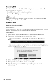
...that matches your motherboard model from MSI website. After the flashing process is off before clearing CMOS data. Click the M-FLASH button and click on Yes to start recovering BIOS. 5. Updating BIOS: 1. Select a BIOS file to the Clear CMOS jumper section for BIOS update. ▪▪Reboot and...the USB flash drive. Press to activate M-Flash for resetting BIOS. Resetting BIOS You might need to restore the default BIOS setting to solve certain problems. There are several ways to reset BIOS: ∙∙Go to BIOS and press F6 to load optimized defaults. ∙∙...
...that matches your motherboard model from MSI website. After the flashing process is off before clearing CMOS data. Click the M-FLASH button and click on Yes to start recovering BIOS. 5. Updating BIOS: 1. Select a BIOS file to the Clear CMOS jumper section for BIOS update. ▪▪Reboot and...the USB flash drive. Press to activate M-Flash for resetting BIOS. Resetting BIOS You might need to restore the default BIOS setting to solve certain problems. There are several ways to reset BIOS: ∙∙Go to BIOS and press F6 to load optimized defaults. ∙∙...

User Manual
Page 47
... and Start to Support page. 2. UEFI BIOS 47 Updating BIOS: 1. After the flashing process is set properly. Install and launch MSI DRAGON CENTER and go to start updating BIOS. 6. Select Live Update and click on Scan button to download and install the latest BIOS file. 5. Click on Advance button. ...3. Select the BIOS file and click on Download icon to search the latest BIOS file. 4. Updating the BIOS with MSI DRAGON CENTER Before updating: Make sure the LAN driver is already...
... and Start to Support page. 2. UEFI BIOS 47 Updating BIOS: 1. After the flashing process is set properly. Install and launch MSI DRAGON CENTER and go to start updating BIOS. 6. Select Live Update and click on Scan button to download and install the latest BIOS file. 5. Click on Advance button. ...3. Select the BIOS file and click on Download icon to search the latest BIOS file. 4. Updating the BIOS with MSI DRAGON CENTER Before updating: Make sure the LAN driver is already...
User Manual
Page 48
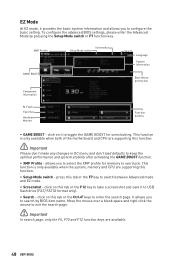
.../ FAT32 format only). ∙∙ Search - This function is only available when the system, memory and CPU are available. 48 UEFI BIOS To configure the advanced BIOS settings, please enter the Advanced Mode by BIOS item name. press this tab or the F7 key to toggle the GAME BOOST for memory to overclock.
.../ FAT32 format only). ∙∙ Search - This function is only available when the system, memory and CPU are available. 48 UEFI BIOS To configure the advanced BIOS settings, please enter the Advanced Mode by BIOS item name. press this tab or the F7 key to toggle the GAME BOOST for memory to overclock.

User Manual
Page 49
you to select language of connected component. ∙∙ Function buttons - The boot priority from high to show the information of BIOS setup. ∙∙ System information - enable or disable these functions by clicking on the CPU, Memory, Storage, Fan Info and Help buttons to...shows ON . ⚠⚠Important The function buttons will vary with the motherboard you purchased. UEFI BIOS 49 shows the CPU/ DDR speed, CPU/ MB temperature, MB/ CPU type, memory size, CPU/ DDR voltage, BIOS version and build date. ∙∙ Boot device priority bar - The function is left to...
you to select language of connected component. ∙∙ Function buttons - The boot priority from high to show the information of BIOS setup. ∙∙ System information - enable or disable these functions by clicking on the CPU, Memory, Storage, Fan Info and Help buttons to...shows ON . ⚠⚠Important The function buttons will vary with the motherboard you purchased. UEFI BIOS 49 shows the CPU/ DDR speed, CPU/ MB temperature, MB/ CPU type, memory size, CPU/ DDR voltage, BIOS version and build date. ∙∙ Boot device priority bar - The function is left to...

User Manual
Page 50
... but also on this button or press the F3 key to update BIOS with a USB flash drive. ∙∙ Hardware Monitor - click on search page. 2. Choose a favorite page and click on this button to enter the Hardware Monitor ...menu that provides the way to show the Favorites window. ∙∙ M-Flash - click on OK. 50 UEFI BIOS It provides 5 menus for you to create personal BIOS menu where you to a favorite menu 1. Right-click or press F2 key. 3. click on this button to enter the M-Flash menu...
... but also on this button or press the F3 key to update BIOS with a USB flash drive. ∙∙ Hardware Monitor - click on search page. 2. Choose a favorite page and click on this button to enter the Hardware Monitor ...menu that provides the way to show the Favorites window. ∙∙ M-Flash - click on OK. 50 UEFI BIOS It provides 5 menus for you to create personal BIOS menu where you to a favorite menu 1. Right-click or press F2 key. 3. click on this button to enter the M-Flash menu...

User Manual
Page 51
Select a BIOS item on OK. Right-click or press F2 key. 3. Choose Delete and click on favorite menu. 2. UEFI BIOS 51 ▪▪To delete a BIOS item from favorite menu 1.
Select a BIOS item on OK. Right-click or press F2 key. 3. Choose Delete and click on favorite menu. 2. UEFI BIOS 51 ▪▪To delete a BIOS item from favorite menu 1.

User Manual
Page 52
...FLASH - provides the information of system. ▪▪BOARD EXPLORER - the following options are available: ▪▪SETTINGS - allows you to update BIOS with a USB flash drive. ▪▪OC PROFILE - Advanced Mode Press Setup Mode switch or F7 function key can switch between EZ Mode and... Advanced Mode in BIOS setup. allows you to be configured. 52 UEFI BIOS provides BIOS setting items and information to specify the parameters for chipset and boot devices. ▪▪OC - allows ...
...FLASH - provides the information of system. ▪▪BOARD EXPLORER - the following options are available: ▪▪SETTINGS - allows you to update BIOS with a USB flash drive. ▪▪OC PROFILE - Advanced Mode Press Setup Mode switch or F7 function key can switch between EZ Mode and... Advanced Mode in BIOS setup. allows you to be configured. 52 UEFI BIOS provides BIOS setting items and information to specify the parameters for chipset and boot devices. ▪▪OC - allows ...

User Manual
Page 53
... SATA/ M.2 device. ⚠⚠Important If the connected SATA/ M.2 device is . Use tab key to 31 can be keyed by BIOS. The month from 1 to switch between time elements. The format is not displayed, turn off computer and re-check SATA/ M.2 cable ...and power cable connections of the device and motherboard. ▶▶System Information Shows detailed system information, including CPU type, BIOS version, and Memory (read only). ▶▶DMI Information Shows system information, desktop Board Information and chassis Information. (Read only). &#...
... SATA/ M.2 device. ⚠⚠Important If the connected SATA/ M.2 device is . Use tab key to 31 can be keyed by BIOS. The month from 1 to switch between time elements. The format is not displayed, turn off computer and re-check SATA/ M.2 cable ...and power cable connections of the device and motherboard. ▶▶System Information Shows detailed system information, including CPU type, BIOS version, and Memory (read only). ▶▶DMI Information Shows system information, desktop Board Information and chassis Information. (Read only). &#...


