
User Manual
Page 12
Contents Quick Start...1 Preparing Tools and Components 1 Safety Information 2 Installing a Processor 3 Installing DDR4 memory 4 Connecting the Front Panel Header 5 Installing the Motherboard 6 Connecting the Power Connectors 7 Installing SATA Drives 8 Installing a Graphics Card 9 Connecting Peripheral Devices 10 Power On...11 Specifications...14 Package contents 19 Block Diagram ...20 Rear I/O Panel...21 LAN Port LED Status Table 21 Audio Ports Configuration 21 Realtek Audio Console 22 Overview of Components 24 CPU Socket...26 DIMM Slots...27 PCI_E1~4: PCIe Expansion Slots 28 ...
Contents Quick Start...1 Preparing Tools and Components 1 Safety Information 2 Installing a Processor 3 Installing DDR4 memory 4 Connecting the Front Panel Header 5 Installing the Motherboard 6 Connecting the Power Connectors 7 Installing SATA Drives 8 Installing a Graphics Card 9 Connecting Peripheral Devices 10 Power On...11 Specifications...14 Package contents 19 Block Diagram ...20 Rear I/O Panel...21 LAN Port LED Status Table 21 Audio Ports Configuration 21 Realtek Audio Console 22 Overview of Components 24 CPU Socket...26 DIMM Slots...27 PCI_E1~4: PCIe Expansion Slots 28 ...

User Manual
Page 13
... LED connectors 41 Onboard LEDs...42 EZ Debug LED...42 LED_SW1: EZ LED Control 42 Installing OS, Drivers & Utilities 43 Installing Windows® 10 43 Installing Drivers 43 Installing Utilities 43 UEFI BIOS...44 BIOS Setup...45 Entering BIOS Setup 45 Resetting BIOS...46 Updating BIOS...46 EZ Mode...48 Advanced Mode ...52 SETTINGS Menu...53 OC Menu...55 M-FLASH Menu...59 OC PROFILE Menu 60 HARDWARE MONITOR Menu 61 RAID Configuration 63 Enabling Intel® Rapid Storage Technology 63 Creating RAID Volume 64 Removing a RAID Volume 65 Resetting Disks to Non-RAID 66 Rebuilding RAID...
... LED connectors 41 Onboard LEDs...42 EZ Debug LED...42 LED_SW1: EZ LED Control 42 Installing OS, Drivers & Utilities 43 Installing Windows® 10 43 Installing Drivers 43 Installing Utilities 43 UEFI BIOS...44 BIOS Setup...45 Entering BIOS Setup 45 Resetting BIOS...46 Updating BIOS...46 EZ Mode...48 Advanced Mode ...52 SETTINGS Menu...53 OC Menu...55 M-FLASH Menu...59 OC PROFILE Menu 60 HARDWARE MONITOR Menu 61 RAID Configuration 63 Enabling Intel® Rapid Storage Technology 63 Creating RAID Volume 64 Removing a RAID Volume 65 Resetting Disks to Non-RAID 66 Rebuilding RAID...

User Manual
Page 14
... PCIe 3.0 x16 slot (from CPU) ∙∙1x PCIe 3.0 x16 slot (x4 mode, from PCH) ∙∙2x PCIe x1 slots (from MSI website. Specifications CPU Chipset Memory Expansion Slot Onboard Graphics Multi-GPU Storage Supports 10th Gen Intel® Core™ and Pentium® Gold / Celeron® processors for LGA 1200 socket* * Please go to the latest version from PCH) * Please refer to page 29 for PCIe 3.0 bandwidth table. ∙∙1x HDMI port, supports...
... PCIe 3.0 x16 slot (from CPU) ∙∙1x PCIe 3.0 x16 slot (x4 mode, from PCH) ∙∙2x PCIe x1 slots (from MSI website. Specifications CPU Chipset Memory Expansion Slot Onboard Graphics Multi-GPU Storage Supports 10th Gen Intel® Core™ and Pentium® Gold / Celeron® processors for LGA 1200 socket* * Please go to the latest version from PCH) * Please refer to page 29 for PCIe 3.0 bandwidth table. ∙∙1x HDMI port, supports...

User Manual
Page 16
... 4-pin ATX 12V power connector ∙∙6x SATA 6Gb/s connectors ∙∙1x USB 3.2 Gen 1 5Gbps Type-C port ∙∙1x USB 3.2 Gen 1 5Gbps connector (support additional 2 USB 3.2 Gen 1 5Gbps ports) ∙∙2x USB 2.0 connectors (support additional 4 USB 2.0 ports) ∙∙1x 4-pin CPU fan connector ∙∙1x 4-pin water pump connector ∙∙6x 4-pin system fan connectors ∙∙1x front panel audio connector ∙∙2x system panel connectors ∙∙1x chassis intrusion connector ∙∙1x Clear CMOS jumper ∙...
... 4-pin ATX 12V power connector ∙∙6x SATA 6Gb/s connectors ∙∙1x USB 3.2 Gen 1 5Gbps Type-C port ∙∙1x USB 3.2 Gen 1 5Gbps connector (support additional 2 USB 3.2 Gen 1 5Gbps ports) ∙∙2x USB 2.0 connectors (support additional 4 USB 2.0 ports) ∙∙1x 4-pin CPU fan connector ∙∙1x 4-pin water pump connector ∙∙6x 4-pin system fan connectors ∙∙1x front panel audio connector ∙∙2x system panel connectors ∙∙1x chassis intrusion connector ∙∙1x Clear CMOS jumper ∙...
User Manual
Page 19
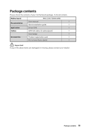
It should contain: Motherboard MAG Z490 TOMAHAWK User manual 1 Documentation Quick installation guide 1 Application Driver DVD 1 Cables SATA 6G cables (2 cables/pack) 1 Case badge 1 Accessories Product registration card 1 M.2 screws (3 pcs./pack) 1 ⚠⚠Important If any of your retailer. Package contents 19 Package contents Please check the contents of the above items are damaged or missing, please contact your motherboard package.
It should contain: Motherboard MAG Z490 TOMAHAWK User manual 1 Documentation Quick installation guide 1 Application Driver DVD 1 Cables SATA 6G cables (2 cables/pack) 1 Case badge 1 Accessories Product registration card 1 M.2 screws (3 pcs./pack) 1 ⚠⚠Important If any of your retailer. Package contents 19 Package contents Please check the contents of the above items are damaged or missing, please contact your motherboard package.

User Manual
Page 38
Keep Data (default) Clear CMOS/ Reset BIOS Resetting BIOS to short JBAT1 for about 5-10 seconds. 3. JTPM1: TPM Module Connector This connector is external powered from JBAT1. 4. Use a jumper cap to default values 1. Remove the jumper cap from a battery located on the computer. Plug the power cord and power on the motherboard to save system configuration data. Please refer to clear the CMOS memory. If you want to clear the system configuration, set the jumper to the TPM security platform manual for...
Keep Data (default) Clear CMOS/ Reset BIOS Resetting BIOS to short JBAT1 for about 5-10 seconds. 3. JTPM1: TPM Module Connector This connector is external powered from JBAT1. 4. Use a jumper cap to default values 1. Remove the jumper cap from a battery located on the computer. Plug the power cord and power on the motherboard to save system configuration data. Please refer to clear the CMOS memory. If you want to clear the system configuration, set the jumper to the TPM security platform manual for...
User Manual
Page 41
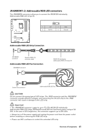
... JRAINBOW connector provide different voltages, and connecting the 5V LED strip to the JRGB connector will result in damage to the LED strip. ⚠⚠Important ∙∙The JRAINBOW connector supports up to 200 LEDs. ∙∙Always turn off the power supply and unplug the power cord from the power outlet before installing or removing the RGB LED strip. ∙∙Please use MSI's software to 75 LEDs WS2812B...
... JRAINBOW connector provide different voltages, and connecting the 5V LED strip to the JRGB connector will result in damage to the LED strip. ⚠⚠Important ∙∙The JRAINBOW connector supports up to 200 LEDs. ∙∙Always turn off the power supply and unplug the power cord from the power outlet before installing or removing the RGB LED strip. ∙∙Please use MSI's software to 75 LEDs WS2812B...

User Manual
Page 43
... Windows Control Panel, you to choose what happens with this disc pop-up your computer in the Drivers/Software tab. 5. Click the Utilities tab. 3. Click OK button to get into Boot Menu. 5. Insert the Windows® 10 installation disc/USB into your computer. 3. If you turn off the AutoPlay feature from the root path of the MSI Driver Disc. 4. Installing Drivers 1. Insert MSI® Driver Disc into your optical drive...
... Windows Control Panel, you to choose what happens with this disc pop-up your computer in the Drivers/Software tab. 5. Click the Utilities tab. 3. Click OK button to get into Boot Menu. 5. Insert the Windows® 10 installation disc/USB into your computer. 3. If you turn off the AutoPlay feature from the root path of the MSI Driver Disc. 4. Installing Drivers 1. Insert MSI® Driver Disc into your optical drive...
User Manual
Page 46
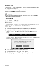
... to start recovering BIOS. 5. Please refer the following methods to enter flash mode. ▪▪Reboot and press Ctrl + F5 key during POST to reboot the system. Updating BIOS Updating BIOS with M-FLASH Before updating: Please download the latest BIOS file that contains the update file into the USB flash drive. When prompted click on Yes to load optimized defaults. ∙∙Short the Clear CMOS jumper on Yes to enter BIOS. Insert the USB flash drive that matches your motherboard model from MSI website...
... to start recovering BIOS. 5. Please refer the following methods to enter flash mode. ▪▪Reboot and press Ctrl + F5 key during POST to reboot the system. Updating BIOS Updating BIOS with M-FLASH Before updating: Please download the latest BIOS file that contains the update file into the USB flash drive. When prompted click on Yes to load optimized defaults. ∙∙Short the Clear CMOS jumper on Yes to enter BIOS. Insert the USB flash drive that matches your motherboard model from MSI website...

User Manual
Page 52
... you to update BIOS with a USB flash drive. ▪▪OC PROFILE - provides BIOS setting items and information to specify the parameters for chipset and boot devices. ▪▪OC - allows you to set the speeds of fans and monitor voltages of installed devices on this motherboard. ∙∙ Menu display - provides the information of system. ▪▪BOARD EXPLORER - the following options are available: ▪▪SETTINGS - allows you to manage overclocking profiles...
... you to update BIOS with a USB flash drive. ▪▪OC PROFILE - provides BIOS setting items and information to specify the parameters for chipset and boot devices. ▪▪OC - allows you to set the speeds of fans and monitor voltages of installed devices on this motherboard. ∙∙ Menu display - provides the information of system. ▪▪BOARD EXPLORER - the following options are available: ▪▪SETTINGS - allows you to manage overclocking profiles...

User Manual
Page 53
... by users. ▶▶System Time Sets the system time. UEFI BIOS 53 The format is not displayed, turn off computer and re-check SATA/ M.2 cable and power cable connections of the device and motherboard. ▶▶System Information Shows detailed system information, including CPU type, BIOS version, and Memory (read only). ▶▶DMI Information Shows system information, desktop Board Information and chassis Information. (Read only). ▶▶Advanced sub-menu...
... by users. ▶▶System Time Sets the system time. UEFI BIOS 53 The format is not displayed, turn off computer and re-check SATA/ M.2 cable and power cable connections of the device and motherboard. ▶▶System Information Shows detailed system information, including CPU type, BIOS version, and Memory (read only). ▶▶DMI Information Shows system information, desktop Board Information and chassis Information. (Read only). ▶▶Advanced sub-menu...
User Manual
Page 54
... different sleep modes. ▶▶Secure Erase+ Enables or disables Secure Erase+ function. The password typed now will be prompted to abort the selection. To clear a set the system boot states and the sequence of system boot devices. ▶▶Security sub-menu Use this menu to set password, press Enter when you to load the BIOS default values or factory default settings into the BIOS and exit the BIOS setup utility with or without changes. 54 UEFI BIOS...
... different sleep modes. ▶▶Secure Erase+ Enables or disables Secure Erase+ function. The password typed now will be prompted to abort the selection. To clear a set the system boot states and the sequence of system boot devices. ▶▶Security sub-menu Use this menu to set password, press Enter when you to load the BIOS default values or factory default settings into the BIOS and exit the BIOS setup utility with or without changes. 54 UEFI BIOS...
User Manual
Page 55
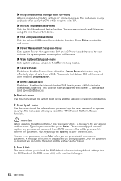
... settings for OC expert to configure in CPU core number. OC Menu This menu allows you to configure the frequencies and voltages for assigned CPU cores group. The target CPU Turbo Ratio value should be higher than former one . Note: We use GAME BOOST function for easy overclocking. ∙∙The BIOS items in OC menu will vary with the processor. ▶▶OC Explore Mode [Expert] Enables or disables...
... settings for OC expert to configure in CPU core number. OC Menu This menu allows you to configure the frequencies and voltages for assigned CPU cores group. The target CPU Turbo Ratio value should be higher than former one . Note: We use GAME BOOST function for easy overclocking. ∙∙The BIOS items in OC menu will vary with the processor. ▶▶OC Explore Mode [Expert] Enables or disables...
User Manual
Page 56
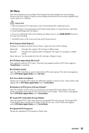
...-menu Press Enter to CPU features. ▶▶CPU Base Clock (MHz) [Default] Sets the CPU Base clock. Read-only. ▶▶GT Ratio [Auto] Sets the integrated graphics ratio. This item appears when a CPU that overclocking behavior and stability is installed. ▶▶CPU Base Clock Apply Mode [Auto]* Sets the applying mode for adjusted CPU base clock. [Auto] This setting will appear when you to set the CPU ratios for heat dissipation when running AVX instructions...
...-menu Press Enter to CPU features. ▶▶CPU Base Clock (MHz) [Default] Sets the CPU Base clock. Read-only. ▶▶GT Ratio [Auto] Sets the integrated graphics ratio. This item appears when a CPU that overclocking behavior and stability is installed. ▶▶CPU Base Clock Apply Mode [Auto]* Sets the applying mode for adjusted CPU base clock. [Auto] This setting will appear when you to set the CPU ratios for heat dissipation when running AVX instructions...
User Manual
Page 57
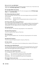
... user to configure the DRAM timing for respective memory channel. ▶▶Advanced DRAM Configuration Press Enter to load the default settings.) ▶▶Memory Fast Boot [Auto] * Enables or disables the initiation and training for all memory channel. This item appears when a CPU that support XMP is installed. ▶▶DRAM Reference Clock [Auto]* Sets the DRAM reference clock. User can setup some protecting conditions about voltage/ current/ temputure for overclocking the memory. The system may become unstable or unbootable after changing memory...
... user to configure the DRAM timing for respective memory channel. ▶▶Advanced DRAM Configuration Press Enter to load the default settings.) ▶▶Memory Fast Boot [Auto] * Enables or disables the initiation and training for all memory channel. This item appears when a CPU that support XMP is installed. ▶▶DRAM Reference Clock [Auto]* Sets the DRAM reference clock. User can setup some protecting conditions about voltage/ current/ temputure for overclocking the memory. The system may become unstable or unbootable after changing memory...

User Manual
Page 58
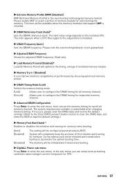
... UEFI BIOS If set to Auto, BIOS will issue a warning message during boot when the CPU or memory has been replaced. [Enabled] [Disabled] The system will set these voltages automatically or you can set it manually. ▶▶DRAM Voltages control [Auto] These options allow you to set the voltages related to PCH. If set the voltages related to CPU. This sub-menu displays all the settings and timings of installed CPU. If set to Disabled, BIOS will set these voltages automatically or you can set...
... UEFI BIOS If set to Auto, BIOS will issue a warning message during boot when the CPU or memory has been replaced. [Enabled] [Disabled] The system will set these voltages automatically or you can set it manually. ▶▶DRAM Voltages control [Auto] These options allow you to set the voltages related to PCH. If set the voltages related to CPU. This sub-menu displays all the settings and timings of installed CPU. If set to Disabled, BIOS will set these voltages automatically or you can set...

User Manual
Page 59
.... UEFI BIOS 59 After the flashing process is 100% completed, the system will appear after rebooting. 4. Click on Yes to update BIOS with a USB flash drive. M-FLASH Menu M-FLASH provides the way to reboot and enter the flash mode. 3. The system will enter the flash mode and a file selection menu will reboot automatically. Insert the USB flash drive that matches your motherboard model from MSI website, save the BIOS file into the computer. 2. Please download the latest BIOS file that...
.... UEFI BIOS 59 After the flashing process is 100% completed, the system will appear after rebooting. 4. Click on Yes to update BIOS with a USB flash drive. M-FLASH Menu M-FLASH provides the way to reboot and enter the flash mode. 3. The system will enter the flash mode and a file selection menu will reboot automatically. Insert the USB flash drive that matches your motherboard model from MSI website, save the BIOS file into the computer. 2. Please download the latest BIOS file that...
User Manual
Page 68
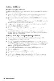
... from the Windows Control Panel, you turn off the AutoPlay feature from the root path of the drivers while installing Windows 10 x64 bit Editions or newer operating system. 1. Insert the MSI USB Drive into the optical drive. 3. Leave the disk/ USB drive in BIOS. 2. As previously mentioned, enable Intel(R) Rapid Storage Technology in the computer until the system reboots itself. Under the Drivers/Software tab, check the Intel RAID Drivers check-box...
... from the Windows Control Panel, you turn off the AutoPlay feature from the root path of the drivers while installing Windows 10 x64 bit Editions or newer operating system. 1. Insert the MSI USB Drive into the optical drive. 3. Leave the disk/ USB drive in BIOS. 2. As previously mentioned, enable Intel(R) Rapid Storage Technology in the computer until the system reboots itself. Under the Drivers/Software tab, check the Intel RAID Drivers check-box...
User Manual
Page 69
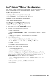
...; memory ready MSI® motherboards ∙∙Supported 10th Gen, or later, Intel® Core™ - Intel® Optane™ Memory Configuration 69 i Processor ∙∙Operating system: Windows 10 64 bit (UEFI mode). ∙∙Intel® Optane™ Memory Module Installing the Intel® Optane™ memory Install the Intel® Rapid Storage Technology. 1. If you turn off the system. ▫▫Refer to the Specifications for location to...
...; memory ready MSI® motherboards ∙∙Supported 10th Gen, or later, Intel® Core™ - Intel® Optane™ Memory Configuration 69 i Processor ∙∙Operating system: Windows 10 64 bit (UEFI mode). ∙∙Intel® Optane™ Memory Module Installing the Intel® Optane™ memory Install the Intel® Rapid Storage Technology. 1. If you turn off the system. ▫▫Refer to the Specifications for location to...

User Manual
Page 72
... BIOS. Troubleshooting Before sending the motherboard for motherboard with another known working graphics card. The USB device is not working ∙∙Make sure your USB drive driver has been installed. ∙∙Verify if USB device is turned on. ∙∙Select different inputs on the monitor. ∙∙If 3 long beeps are heard, remove all memory modules and try to go over troubleshooting guide first to lose all ATX power connectors like ATX_PWR1, CPU_PWR1 are connected...
... BIOS. Troubleshooting Before sending the motherboard for motherboard with another known working graphics card. The USB device is not working ∙∙Make sure your USB drive driver has been installed. ∙∙Verify if USB device is turned on. ∙∙Select different inputs on the monitor. ∙∙If 3 long beeps are heard, remove all memory modules and try to go over troubleshooting guide first to lose all ATX power connectors like ATX_PWR1, CPU_PWR1 are connected...


