
User Manual
Page 12
...: Chassis Intrusion Connector 34 JTPM1: TPM Module Connector 34 JRGB1~2: RGB LED Connectors 35 JTBT1: Thunderbolt Add-on Card Connector 35 JBAT1: Clear CMOS (Reset BIOS) Jumper 36 EZ Debug LED...36 12 Contents
...: Chassis Intrusion Connector 34 JTPM1: TPM Module Connector 34 JRGB1~2: RGB LED Connectors 35 JTBT1: Thunderbolt Add-on Card Connector 35 JBAT1: Clear CMOS (Reset BIOS) Jumper 36 EZ Debug LED...36 12 Contents

User Manual
Page 13
... 38 Installing Windows® 10 38 Installing Drivers 38 Installing Utilities 38 MYSTIC LIGHT...39 Device LED effect control screen 39 BIOS Setup ...42 Entering BIOS Setup 42 Resetting BIOS...43 Updating BIOS...43 EZ Mode ...44 Advanced Mode ...46 SETTINGS...47 Advanced...47 Boot...54 Security ...55 Save & Exit...56 OC...57 M-FLASH...
... 38 Installing Windows® 10 38 Installing Drivers 38 Installing Utilities 38 MYSTIC LIGHT...39 Device LED effect control screen 39 BIOS Setup ...42 Entering BIOS Setup 42 Resetting BIOS...43 Updating BIOS...43 EZ Mode ...44 Advanced Mode ...46 SETTINGS...47 Advanced...47 Boot...54 Security ...55 Save & Exit...56 OC...57 M-FLASH...

User Manual
Page 14
... installing SATA M.2 SSD in M2_1 slot. ** Before using Intel® Optane™ memory modules, please ensure that you have updated the drivers and BIOS to the latest version from MSI website. y 2x PCIe 3.0 x16 slots (support x16/x4 modes) y 1x PCIe 3.0 x1 slot y 1 x M.2 slot (Key E) for an Intel® CNVi wireless module...(OC)/ 2666/ 2400/ 2133 MHz* y Supports Dual-Channel mode y Supports non-ECC, un-buffered memory y Supports Intel® Extreme Memory Profile (XMP) * Please refer www.msi.com for more information on next page 14 Specifications
... installing SATA M.2 SSD in M2_1 slot. ** Before using Intel® Optane™ memory modules, please ensure that you have updated the drivers and BIOS to the latest version from MSI website. y 2x PCIe 3.0 x16 slots (support x16/x4 modes) y 1x PCIe 3.0 x1 slot y 1 x M.2 slot (Key E) for an Intel® CNVi wireless module...(OC)/ 2666/ 2400/ 2133 MHz* y Supports Dual-Channel mode y Supports non-ECC, un-buffered memory y Supports Intel® Extreme Memory Profile (XMP) * Please refer www.msi.com for more information on next page 14 Specifications

User Manual
Page 16
... y CPU/System temperature detection y CPU/System fan speed detection y CPU/System fan speed control Form Factor y Micro-ATX Form Factor y 9.6 in . (24.4 cm x 24.4 cm) BIOS Features y 1x 128 Mb flash y UEFI AMI BIOS y ACPI 6.1, SMBIOS 2.8 y Multi-language Continued on next page 16 Specifications x 9.6 in .
... y CPU/System temperature detection y CPU/System fan speed detection y CPU/System fan speed control Form Factor y Micro-ATX Form Factor y 9.6 in . (24.4 cm x 24.4 cm) BIOS Features y 1x 128 Mb flash y UEFI AMI BIOS y ACPI 6.1, SMBIOS 2.8 y Multi-language Continued on next page 16 Specifications x 9.6 in .

User Manual
Page 25
...~2 Fan Connectors CPU_PWR1, ATX_PWR1 Power Connectors CPU Socket LGA1151 CPU Socket DIMMA1, DIMMA2, DIMMB1, DIMMB2 DIMM Slots JAUD1 Front Audio Connector JBAT1 Clear CMOS (Reset BIOS) Jumper JCI1 Chassis Intrusion Connector JFP1, JFP2 Front Panel Connectors JRGB1~2 RGB LED Connectors JTBT1 Thunderbolt Add-on Card Connector JTPM1 TPM Module Connector JUSB1...
...~2 Fan Connectors CPU_PWR1, ATX_PWR1 Power Connectors CPU Socket LGA1151 CPU Socket DIMMA1, DIMMA2, DIMMB1, DIMMB2 DIMM Slots JAUD1 Front Audio Connector JBAT1 Clear CMOS (Reset BIOS) Jumper JCI1 Chassis Intrusion Connector JFP1, JFP2 Front Panel Connectors JRGB1~2 RGB LED Connectors JTBT1 Thunderbolt Add-on Card Connector JTPM1 TPM Module Connector JUSB1...

User Manual
Page 27
... a lower frequency than 4GB memory on its Serial Presence Detect (SPD). y Based on Intel CPU specification, the Memory DIMM voltage below 1.35V is recommended to BIOS and find the Memory Try It!
... a lower frequency than 4GB memory on its Serial Presence Detect (SPD). y Based on Intel CPU specification, the Memory DIMM voltage below 1.35V is recommended to BIOS and find the Memory Try It!

User Manual
Page 33
... the instruction below to adjust the fan connector to PWM or DC Mode. When you to adjust fan speed in relation to a fan connector in BIOS > HARDWARE MONITOR. Important Make sure fans are gradient points of the fan speed that allow you plug a 3-pin (Non-PWM) fan to CPU temperature. DC...
... the instruction below to adjust the fan connector to PWM or DC Mode. When you to adjust fan speed in relation to a fan connector in BIOS > HARDWARE MONITOR. Important Make sure fans are gradient points of the fan speed that allow you plug a 3-pin (Non-PWM) fan to CPU temperature. DC...

User Manual
Page 34
... data pin2 10 No Pin 11 LPC address & data pin3 12 Ground 13 LPC Frame 14 Ground 34 Overview of Components Set Chassis Intrusion to BIOS > Settings > Security > Chassis Intrusion Configuration. 4. Please refer to select Yes. Normal (default) Trigger the chassis intrusion event Using chassis intrusion detector... warning 1. JCI1: Chassis Intrusion Connector This connector allows you to Enabled. 5. Close the chassis cover. 3. Connect the JCI1 connector to BIOS > Settings > Security > Chassis Intrusion Configuration. 2. Go to the chassis intrusion switch/ sensor on .
... data pin2 10 No Pin 11 LPC address & data pin3 12 Ground 13 LPC Frame 14 Ground 34 Overview of Components Set Chassis Intrusion to BIOS > Settings > Security > Chassis Intrusion Configuration. 4. Please refer to select Yes. Normal (default) Trigger the chassis intrusion event Using chassis intrusion detector... warning 1. JCI1: Chassis Intrusion Connector This connector allows you to Enabled. 5. Close the chassis cover. 3. Connect the JCI1 connector to BIOS > Settings > Security > Chassis Intrusion Configuration. 2. Go to the chassis intrusion switch/ sensor on .

User Manual
Page 36
Keep Data (default) Clear CMOS/ Reset BIOS Resetting BIOS to clear the CMOS memory. indicates CPU is not detected or fail. DRAM - VGA - If you want to clear the system configuration, set the jumpers ... GPU is not detected or fail. 36 Overview of the motherboard. indicates the booting device is not detected or fail. BOOT - JBAT1: Clear CMOS (Reset BIOS) Jumper There is CMOS memory onboard that is external powered from JBAT1. 4. Remove the jumper cap from a battery located on the computer. EZ Debug LED...
Keep Data (default) Clear CMOS/ Reset BIOS Resetting BIOS to clear the CMOS memory. indicates CPU is not detected or fail. DRAM - VGA - If you want to clear the system configuration, set the jumpers ... GPU is not detected or fail. 36 Overview of the motherboard. indicates the booting device is not detected or fail. BOOT - JBAT1: Clear CMOS (Reset BIOS) Jumper There is CMOS memory onboard that is external powered from JBAT1. 4. Remove the jumper cap from a battery located on the computer. EZ Debug LED...

User Manual
Page 42
... menu F5: Enter Memory-Z menu F6: Load optimized defaults F7: Switch between Yes or No to confirm your choice. 42 BIOS Setup Ctrl+F: Enter Search page * When you purchased. y In MSI Dragon Center application, click on the screen during the boot process. Select between Advanced mode and EZ mode F8: Load Overclocking...
... menu F5: Enter Memory-Z menu F6: Load optimized defaults F7: Switch between Yes or No to confirm your choice. 42 BIOS Setup Ctrl+F: Enter Search page * When you purchased. y In MSI Dragon Center application, click on the screen during the boot process. Select between Advanced mode and EZ mode F8: Load Overclocking...
User Manual
Page 43
... mode. Important Be sure the computer is 100% completed, the system will restart automatically. Please refer to start updating BIOS. 6. Updating BIOS Updating BIOS with MSI DRAGON CENTER Before updating: Make sure the LAN driver is already installed and the Internet connection is 100% completed, the... 3. And then click Next and Start to the Clear CMOS jumper section for resetting BIOS. Select a BIOS file to load optimized defaults. Install and launch MSI DRAGON CENTER. 2. Click on Yes to enter BIOS. Please refer the following methods to enter flash mode. ƒ Reboot and press ...
... mode. Important Be sure the computer is 100% completed, the system will restart automatically. Please refer to start updating BIOS. 6. Updating BIOS Updating BIOS with MSI DRAGON CENTER Before updating: Make sure the LAN driver is already installed and the Internet connection is 100% completed, the... 3. And then click Next and Start to the Clear CMOS jumper section for resetting BIOS. Select a BIOS file to load optimized defaults. Install and launch MSI DRAGON CENTER. 2. Click on Yes to enter BIOS. Please refer the following methods to enter flash mode. ƒ Reboot and press ...

User Manual
Page 44
...BOOST switch Boot device priority bar Information display M-Flash Favorites Hardware Monitor Function buttons y GAME BOOST switch - Switch the outer circle to right. 44 BIOS Setup Move the mouse over a blank space and right click the mouse to switch between Advanced mode and EZ mode. y System information - y XMP... to configure the basic setting. EZ Mode At EZ mode, it provides the basic system information and allows you to select the language of BIOS setup. click on the inner circle to enable/ disable the X.M.P. (Extreme Memory Profile). click on this tab or the F12 key to ...
...BOOST switch Boot device priority bar Information display M-Flash Favorites Hardware Monitor Function buttons y GAME BOOST switch - Switch the outer circle to right. 44 BIOS Setup Move the mouse over a blank space and right click the mouse to switch between Advanced mode and EZ mode. y System information - y XMP... to configure the basic setting. EZ Mode At EZ mode, it provides the basic system information and allows you to select the language of BIOS setup. click on the inner circle to enable/ disable the X.M.P. (Extreme Memory Profile). click on this tab or the F12 key to ...

User Manual
Page 45
...-used / favorite BIOS setting items in one page. ƒ To add a BIOS item to add the frequently-used BIOS setting items. ƒ Default HomePage - y M-Flash - click on left side to update BIOS with a USB flash drive. Move the mouse over a BIOS item not only on BIOS menu but also on... Optane Genie, HD audio controller, AHCI/ RAID, CPU Fan Fail Warning Control and BIOS Log Review by percentage. press the F3 key to select a BIOS menu (e.g. It allows you to create personal BIOS menu where you to manually control the fan speed by clicking on their respective button....
...-used / favorite BIOS setting items in one page. ƒ To add a BIOS item to add the frequently-used BIOS setting items. ƒ Default HomePage - y M-Flash - click on left side to update BIOS with a USB flash drive. Move the mouse over a BIOS item not only on BIOS menu but also on... Optane Genie, HD audio controller, AHCI/ RAID, CPU Fan Fail Warning Control and BIOS Log Review by percentage. press the F3 key to select a BIOS menu (e.g. It allows you to create personal BIOS menu where you to manually control the fan speed by clicking on their respective button....

User Manual
Page 46
Advanced Mode Press Setup Mode switch or F7 function key can switch between EZ Mode and Advanced Mode in BIOS setup. the following options are available: ƒ SETTINGS - Increasing the frequency may get better performance. ƒ M-FLASH - allows you to manage ... a USB flash drive. ƒ OC PROFILE - XMP switch Setup Mode switch Screenshot Search Language System information Boot device priority bar BIOS menu selection BIOS menu selection Menu display y GAME BOOST switch/ XMP switch/ Setup Mode switch/ Screenshot/ Language/ Search/ System information/ Boot device priority bar ...
Advanced Mode Press Setup Mode switch or F7 function key can switch between EZ Mode and Advanced Mode in BIOS setup. the following options are available: ƒ SETTINGS - Increasing the frequency may get better performance. ƒ M-FLASH - allows you to manage ... a USB flash drive. ƒ OC PROFILE - XMP switch Setup Mode switch Screenshot Search Language System information Boot device priority bar BIOS menu selection BIOS menu selection Menu display y GAME BOOST switch/ XMP switch/ Setup Mode switch/ Screenshot/ Language/ Search/ System information/ Boot device priority bar ...

User Manual
Page 47
...The month from Sun to 31 can be keyed by users. The date from 1 to Sat, determined by BIOS. The year can be adjusted by numeric function keys. BIOS Setup 47 The time format is not displayed, turn off computer and re-check SATA cable and power cable connections...system date. through Dec. Press Enter to switch between date elements. The format is . f System Information Shows detailed system information, including CPU type, BIOS version, and Memory (read only). Read-only. f SATA PortX/ M2_X Shows the information of the device and motherboard. Use tab key to enter...
...The month from Sun to 31 can be keyed by users. The date from 1 to Sat, determined by BIOS. The year can be adjusted by numeric function keys. BIOS Setup 47 The time format is not displayed, turn off computer and re-check SATA cable and power cable connections...system date. through Dec. Press Enter to switch between date elements. The format is . f System Information Shows detailed system information, including CPU type, BIOS version, and Memory (read only). Read-only. f SATA PortX/ M2_X Shows the information of the device and motherboard. Use tab key to enter...

User Manual
Page 48
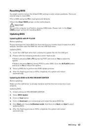
...Color] The power LED turns to another color to indicate the S3 state. [Blinking] The power LED blinks to be configured automatically by BIOS. [Gen1] Enables PCIe Gen1 support only. [Gen2] Enables PCIe Gen2 support only. [Gen3] Enables PCIe Gen3 support only. fPower LED...legacy network Boot Option ROM for optimizing IPv4 / IPv6 function. [Enabled] Enables UEFI network stack. [Disabled] Disables UEFI network stack. 48 BIOS Setup fNetwork Stack [Disabled] Sets UEFI network stack for detailed settings. f Integrated Peripherals Sets integrated peripherals' parameters, such as LAN, HDD,...
...Color] The power LED turns to another color to indicate the S3 state. [Blinking] The power LED blinks to be configured automatically by BIOS. [Gen1] Enables PCIe Gen1 support only. [Gen2] Enables PCIe Gen2 support only. [Gen3] Enables PCIe Gen3 support only. fPower LED...legacy network Boot Option ROM for optimizing IPv4 / IPv6 function. [Enabled] Enables UEFI network stack. [Disabled] Disables UEFI network stack. 48 BIOS Setup fNetwork Stack [Disabled] Sets UEFI network stack for detailed settings. f Integrated Peripherals Sets integrated peripherals' parameters, such as LAN, HDD,...
User Manual
Page 49
... Hot Plug [Disabled] Allows user to enter the sub-menu. fHD Audio Controller [Enabled] Enables or disables the onboard High Definition Audio controller. BIOS Setup 49
... Hot Plug [Disabled] Allows user to enter the sub-menu. fHD Audio Controller [Enabled] Enables or disables the onboard High Definition Audio controller. BIOS Setup 49
User Manual
Page 50
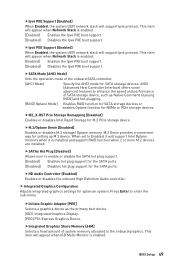
... when Initiate Graphic Adapter set to PEG. [Enabled] Enables multi-screen function for the operating system without XHCI hand-off ) before AC power loss. 50 BIOS Setup f Power Management Setup Sets system Power Management of ErP and AC Power Loss behaviors. It will be unavailable under legacy mode. [Disabled] The USB...
... when Initiate Graphic Adapter set to PEG. [Enabled] Enables multi-screen function for the operating system without XHCI hand-off ) before AC power loss. 50 BIOS Setup f Power Management Setup Sets system Power Management of ErP and AC Power Loss behaviors. It will be unavailable under legacy mode. [Disabled] The USB...
User Manual
Page 51
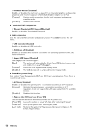
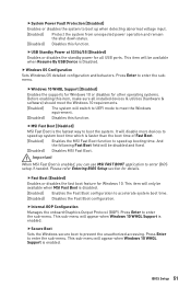
...the Fast Boot configuration. This sub-menu will only be disabled and fixed. [Disabled] Disables MSI Fast Boot. This sub-menu will be available when MSI Fast Boot is enabled. Please refer Entering BIOS Setup section for Windows 10. fFast Boot [Enabled] Enables or disables the fast boot feature ...for details. fInternal GOP Configuration Manages the onboard Graphics Output Protocol (GOP). BIOS Setup 51 And the following Fast Boot field will appear when Windows 10 WHQL Support is enabled, you can use MSI FAST BOOT application to enter the sub-menu. Press Enter to enter the ...
...the Fast Boot configuration. This sub-menu will only be disabled and fixed. [Disabled] Disables MSI Fast Boot. This sub-menu will be available when MSI Fast Boot is enabled. Please refer Entering BIOS Setup section for Windows 10. fFast Boot [Enabled] Enables or disables the fast boot feature ...for details. fInternal GOP Configuration Manages the onboard Graphics Output Protocol (GOP). BIOS Setup 51 And the following Fast Boot field will appear when Windows 10 WHQL Support is enabled, you can use MSI FAST BOOT application to enter the sub-menu. Press Enter to enter the ...
User Manual
Page 52
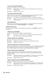
... Boot Mode sets to Custom. This item appears when Secure Boot Support is to select how the secure boot keys be awakened from BIOS. [Custom] Allows user to configure the secure boot settings and manually load the secure keys. fResume By RTC Alarm [Disabled] Disables... ) on a scheduled time/ date. [Disabled] Disables this function. If Resume By RTC Alarm is detected. [Disabled] Disables this function. 52 BIOS Setup fKey Management Manages the secure boot keys. This submenu will automatically resume (boot up by third party integrated chips. [Enabled] Enables the system ...
... Boot Mode sets to Custom. This item appears when Secure Boot Support is to select how the secure boot keys be awakened from BIOS. [Custom] Allows user to configure the secure boot settings and manually load the secure keys. fResume By RTC Alarm [Disabled] Disables... ) on a scheduled time/ date. [Disabled] Disables this function. If Resume By RTC Alarm is detected. [Disabled] Disables this function. 52 BIOS Setup fKey Management Manages the secure boot keys. This submenu will automatically resume (boot up by third party integrated chips. [Enabled] Enables the system ...


