
User Manual
Page 13
...: USB 3.2 Gen 2 10Gbps Type-C Connector 38 JAUD1: Front Audio Connector 38 JCI1: Chassis Intrusion Connector 39 JCOM1: Serial Port Connector 39 JBAT1: Clear CMOS (Reset BIOS) Jumper 40 Contents 13
...: USB 3.2 Gen 2 10Gbps Type-C Connector 38 JAUD1: Front Audio Connector 38 JCI1: Chassis Intrusion Connector 39 JCOM1: Serial Port Connector 39 JBAT1: Clear CMOS (Reset BIOS) Jumper 40 Contents 13

User Manual
Page 14
...~2: Addressable RGB LED connectors 42 Installing OS, Drivers & Utilities 43 Installing Windows® 10 43 Installing Drivers 43 Installing Utilities 43 BIOS Setup ...44 Entering BIOS Setup 44 Resetting BIOS...45 Updating BIOS...45 EZ Mode ...47 Advanced Mode ...49 SETTINGS...50 Advanced...50 Boot...55 Security ...56 Save & Exit...57 OC...58 M-FLASH...
...~2: Addressable RGB LED connectors 42 Installing OS, Drivers & Utilities 43 Installing Windows® 10 43 Installing Drivers 43 Installing Utilities 43 BIOS Setup ...44 Entering BIOS Setup 44 Resetting BIOS...45 Updating BIOS...45 EZ Mode ...47 Advanced Mode ...49 SETTINGS...50 Advanced...50 Boot...55 Security ...56 Save & Exit...57 OC...58 M-FLASH...

User Manual
Page 17
.../ System/ Chipset temperature detection ∙∙CPU/ System/ Chipset fan speed detection ∙∙CPU/ System/ Chipset fan speed control ∙∙AMD® X570 Chipset ▪▪3x USB 3.2 Gen 2 10Gbps ports (2 Type-A ports on the back panel, 1 Type-C internal connector) ▪▪4x USB 3.2...;2x USB 3.2 Gen 1 5Gbps Type-A ports on the back panel ∙∙1x Flash BIOS Button ∙∙1x PS/2 keyboard/ mouse combo port ∙∙2x USB 2.0 ports ∙∙2x WiFi/ Bluetooth antenna jacks ∙∙2x USB 3.2 Gen 1 5Gbps ports ∙∙1x HDMI...
.../ System/ Chipset temperature detection ∙∙CPU/ System/ Chipset fan speed detection ∙∙CPU/ System/ Chipset fan speed control ∙∙AMD® X570 Chipset ▪▪3x USB 3.2 Gen 2 10Gbps ports (2 Type-A ports on the back panel, 1 Type-C internal connector) ▪▪4x USB 3.2...;2x USB 3.2 Gen 1 5Gbps Type-A ports on the back panel ∙∙1x Flash BIOS Button ∙∙1x PS/2 keyboard/ mouse combo port ∙∙2x USB 2.0 ports ∙∙2x WiFi/ Bluetooth antenna jacks ∙∙2x USB 3.2 Gen 1 5Gbps ports ∙∙1x HDMI...

User Manual
Page 18
...;2x 4-pin RGB LED connectors ∙∙2x 3-pin RAINBOW LED connectors ∙∙4x EZ Debug LEDs BIOS Features ∙∙1x 256 Mb flash ∙∙UEFI AMI BIOS ∙∙ACPI 6.1, SM BIOS 2.8 ∙∙ Multi-language Form Factor ∙∙ATX Form Factor ∙∙12 in . (30.5 cm...
...;2x 4-pin RGB LED connectors ∙∙2x 3-pin RAINBOW LED connectors ∙∙4x EZ Debug LEDs BIOS Features ∙∙1x 256 Mb flash ∙∙UEFI AMI BIOS ∙∙ACPI 6.1, SM BIOS 2.8 ∙∙ Multi-language Form Factor ∙∙ATX Form Factor ∙∙12 in . (30.5 cm...

User Manual
Page 20
... ▪▪GAME Boost ▪▪USB with type A+C ▪▪AMD Turbo USB 3.2 Gen 2 ▪▪Dual CPU Power ∙∙ BIOS ▪▪Click BIOS 5 ▪▪Flash BIOS Button ∙∙Gamer Experience ▪▪DRAGON CENTER ▪▪GAMING HOTKEY ▪▪GAMING MOUSE Control ▪▪USB SPEED...
... ▪▪GAME Boost ▪▪USB with type A+C ▪▪AMD Turbo USB 3.2 Gen 2 ▪▪Dual CPU Power ∙∙ BIOS ▪▪Click BIOS 5 ▪▪Flash BIOS Button ∙∙Gamer Experience ▪▪DRAGON CENTER ▪▪GAMING HOTKEY ▪▪GAMING MOUSE Control ▪▪USB SPEED...

User Manual
Page 23
... (●: connected, Blank: empty) Rear I /O Panel Wi-Fi Antenna connectors USB 3.2 Gen 2 10Gbps Type-A* PS/2 USB 3.2 Gen 1 5Gbps Type-A 2.5Gbps LAN Audio Ports Flash BIOS Button Flash BIOS Port USB 2.0 Type-A USB 3.2 Gen 2 10Gbps Type-A USB 3.2 Gen 2 10Gbps Type-C* Optical S/PDIF-Out *USB 3.2 Gen 2 10Gbps (3rd Gen AMD Ryzen™) or USB... 3.2 Gen 1 5Gbps (2nd Gen AMD Ryzen™/Ryzen™ with Radeon™ Vega Graphics and 2nd Gen AMD Ryzen™ with Flash BIOS Button. Rear I /O Panel 23 Please refer to page 46 for Updating...
... (●: connected, Blank: empty) Rear I /O Panel Wi-Fi Antenna connectors USB 3.2 Gen 2 10Gbps Type-A* PS/2 USB 3.2 Gen 1 5Gbps Type-A 2.5Gbps LAN Audio Ports Flash BIOS Button Flash BIOS Port USB 2.0 Type-A USB 3.2 Gen 2 10Gbps Type-A USB 3.2 Gen 2 10Gbps Type-C* Optical S/PDIF-Out *USB 3.2 Gen 2 10Gbps (3rd Gen AMD Ryzen™) or USB... 3.2 Gen 1 5Gbps (2nd Gen AMD Ryzen™/Ryzen™ with Radeon™ Vega Graphics and 2nd Gen AMD Ryzen™ with Flash BIOS Button. Rear I /O Panel 23 Please refer to page 46 for Updating...

User Manual
Page 28
...~4 Fan Connectors CPU_PWR1~2, ATX_PWR1 Power Connectors CPU Socket AM4 CPU Socket DIMMA1/A2/B1/B2 DIMM Slots JAUD1 Front Audio Connector JBAT1 Clear CMOS (Reset BIOS) Jumper JCI1 Chassis Intrusion Connector JCOM1 Serial Port Connector JFP1, JFP2 Front Panel Connectors JRAINBOW1~2 Addressable RGB LED connectors JRGB1~2 RGB LED connectors JUSB1~2 USB...
...~4 Fan Connectors CPU_PWR1~2, ATX_PWR1 Power Connectors CPU Socket AM4 CPU Socket DIMMA1/A2/B1/B2 DIMM Slots JAUD1 Front Audio Connector JBAT1 Clear CMOS (Reset BIOS) Jumper JCI1 Chassis Intrusion Connector JCOM1 Serial Port Connector JFP1, JFP2 Front Panel Connectors JRAINBOW1~2 Addressable RGB LED connectors JRGB1~2 RGB LED connectors JUSB1~2 USB...

User Manual
Page 29
... please make sure the cooling fans work properly to the AM4 processor's architecture. ∙∙Always unplug the power cord from overheating. MSI® does not guarantee the damages or risks caused by inadequate operation beyond product specifications is the Pin 1 indicator. ⚠⚠Important... ∙∙When changing the processor, the system configuration could be cleared and reset BIOS to default values, due to protect the CPU from the power outlet before booting your system. ∙∙Overheating can tolerate overclocking.
... please make sure the cooling fans work properly to the AM4 processor's architecture. ∙∙Always unplug the power cord from overheating. MSI® does not guarantee the damages or risks caused by inadequate operation beyond product specifications is the Pin 1 indicator. ⚠⚠Important... ∙∙When changing the processor, the system configuration could be cleared and reset BIOS to default values, due to protect the CPU from the power outlet before booting your system. ∙∙Overheating can tolerate overclocking.

User Manual
Page 30
Go to BIOS and find the DRAM Frequency to set the memory frequency if you want to operate the memory at the marked or at a lower frequency than ... or overclocking. ∙∙The stability and compatibility of installed memory module depend on installed CPU and devices when overclocking. ∙∙Please refer www.msi.com for more information on its Serial Presence Detect (SPD). DIMM Slots DIMMA1 DIMMB1 Channel A Channel B DIMMA2 Memory module installation recommendation DIMMB2 DIMMA2 DIMMA2 DIMMB2...
Go to BIOS and find the DRAM Frequency to set the memory frequency if you want to operate the memory at the marked or at a lower frequency than ... or overclocking. ∙∙The stability and compatibility of installed memory module depend on installed CPU and devices when overclocking. ∙∙Please refer www.msi.com for more information on its Serial Presence Detect (SPD). DIMM Slots DIMMA1 DIMMB1 Channel A Channel B DIMMA2 Memory module installation recommendation DIMMB2 DIMMA2 DIMMA2 DIMMB2...

User Manual
Page 36
..., PUMP_FAN1, SYS_FAN1~4: Fan Connectors Fan connectors can switch between PWM mode and DC mode and adjust fan speed in relation to adjust fan speed in BIOS > HARDWARE MONITOR.
..., PUMP_FAN1, SYS_FAN1~4: Fan Connectors Fan connectors can switch between PWM mode and DC mode and adjust fan speed in relation to adjust fan speed in BIOS > HARDWARE MONITOR.

User Manual
Page 39
... > Security > Chassis Intrusion Configuration. 4. Normal (default) Trigger the chassis intrusion event Using chassis intrusion detector 1. Resetting the chassis intrusion warning 1. Go to BIOS > SETTINGS > Security > Chassis Intrusion Configuration. 2. Set Chassis Intrusion to connect the optional serial port with bracket. 2 10 1 9 1 DCD 2 SIN 3 SOUT 4 DTR 5 Ground 6 DSR 7 RTS 8 CTS 9 ...
... > Security > Chassis Intrusion Configuration. 4. Normal (default) Trigger the chassis intrusion event Using chassis intrusion detector 1. Resetting the chassis intrusion warning 1. Go to BIOS > SETTINGS > Security > Chassis Intrusion Configuration. 2. Set Chassis Intrusion to connect the optional serial port with bracket. 2 10 1 9 1 DCD 2 SIN 3 SOUT 4 DTR 5 Ground 6 DSR 7 RTS 8 CTS 9 ...

User Manual
Page 40
... on the motherboard to short JBAT1 for about 5-10 seconds. 3. indicates the booting device is external powered from JBAT1. 4. JBAT1: Clear CMOS (Reset BIOS) Jumper There is CMOS memory onboard that is not detected or fail. 40 Overview of the motherboard. Keep Data (default) Clear CMOS/ Reset... BIOS Resetting BIOS to clear the CMOS memory. indicates GPU is not detected or fail. indicates CPU is not detected or fail. EZ Debug LED These LEDs...
... on the motherboard to short JBAT1 for about 5-10 seconds. 3. indicates the booting device is external powered from JBAT1. 4. JBAT1: Clear CMOS (Reset BIOS) Jumper There is CMOS memory onboard that is not detected or fail. 40 Overview of the motherboard. Keep Data (default) Clear CMOS/ Reset... BIOS Resetting BIOS to clear the CMOS memory. indicates GPU is not detected or fail. indicates CPU is not detected or fail. EZ Debug LED These LEDs...

User Manual
Page 44
...CPU Specifications menu F5: Enter Memory-Z menu F6: Load optimized defaults F7: Switch between Yes or No to the HELP information panel for BIOS item description. ∙∙The pictures in normal conditions. Select between Advanced mode and EZ mode F8: Load Overclocking Profile F9: Save ...Change and Reset* F12: Take a screenshot and save it provides the modification information. You could also refer to confirm your choice. 44 BIOS Setup You should be slightly different from the product you press F10, a confirmation window appears and it to enter Boot Menu message appears ...
...CPU Specifications menu F5: Enter Memory-Z menu F6: Load optimized defaults F7: Switch between Yes or No to the HELP information panel for BIOS item description. ∙∙The pictures in normal conditions. Select between Advanced mode and EZ mode F8: Load Overclocking Profile F9: Save ...Change and Reset* F12: Take a screenshot and save it provides the modification information. You could also refer to confirm your choice. 44 BIOS Setup You should be slightly different from the product you press F10, a confirmation window appears and it to enter Boot Menu message appears ...
User Manual
Page 45
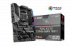
... POST and click on Yes to reboot the system. 3. Updating BIOS: 1. After the flashing process is set properly. Insert the USB flash drive that matches your motherboard model from MSI website. Updating BIOS Updating BIOS with MSI DRAGON CENTER Before updating: Make sure the LAN driver is already... installed and the internet connection is 100% completed, the system will reboot automatically. Updating BIOS: 1. And then save the BIOS file into the USB port. 2. Install and launch MSI DRAGON CENTER. 2. Click the M-FLASH button and click on Yes to reboot the system. &#...
... POST and click on Yes to reboot the system. 3. Updating BIOS: 1. After the flashing process is set properly. Insert the USB flash drive that matches your motherboard model from MSI website. Updating BIOS Updating BIOS with MSI DRAGON CENTER Before updating: Make sure the LAN driver is already... installed and the internet connection is 100% completed, the system will reboot automatically. Updating BIOS: 1. And then save the BIOS file into the USB port. 2. Install and launch MSI DRAGON CENTER. 2. Click the M-FLASH button and click on Yes to reboot the system. &#...
User Manual
Page 46
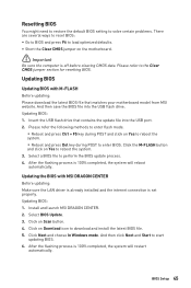
... root of your drive, go to Properties. 46 BIOS Setup Connect the power supply to CPU_PWR1 and ATX_PWR1. (No need to flash BIOS, and the LED starts flashing. 6. Plug the USB flash drive that matches your motherboard model from the MSI® website. 2. The LED will be turned ...the process is completed. ⚠⚠Important Only the FAT32 format USB flash drive supports updating BIOS by Flash BIOS Button. Please download the latest BIOS file that contains the MSI.ROM file into the Flash BIOS Port on the drive icon and go to Windows Explorer, right click on the rear I/O panel...
... root of your drive, go to Properties. 46 BIOS Setup Connect the power supply to CPU_PWR1 and ATX_PWR1. (No need to flash BIOS, and the LED starts flashing. 6. Plug the USB flash drive that matches your motherboard model from the MSI® website. 2. The LED will be turned ...the process is completed. ⚠⚠Important Only the FAT32 format USB flash drive supports updating BIOS by Flash BIOS Button. Please download the latest BIOS file that contains the MSI.ROM file into the Flash BIOS Port on the drive icon and go to Windows Explorer, right click on the rear I/O panel...
User Manual
Page 47
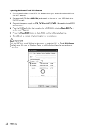
...Screenshot - The boot priority from high to low is left to change the boot priority. click on the inner circle to select language of BIOS setup. ∙∙ System information - A-XMP switch Setup Mode switch Screenshot Search Language System information GAME BOOST switch Boot device priority bar ... function. ∙∙ Setup Mode switch - you can move the device icons to right. To configure the advanced BIOS settings, please enter the Advanced Mode by BIOS item name. Switch the outer circle to select the memory profile if any changes in OC menu and don't load ...
...Screenshot - The boot priority from high to low is left to change the boot priority. click on the inner circle to select language of BIOS setup. ∙∙ System information - A-XMP switch Setup Mode switch Screenshot Search Language System information GAME BOOST switch Boot device priority bar ... function. ∙∙ Setup Mode switch - you can move the device icons to right. To configure the advanced BIOS settings, please enter the Advanced Mode by BIOS item name. Switch the outer circle to select the memory profile if any changes in OC menu and don't load ...
User Manual
Page 48
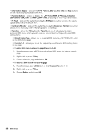
...information. ∙∙ Function buttons - It allows you can save and access favorite/ frequently-used / favorite BIOS setting items in one page. ▪▪To add a BIOS item to select a BIOS menu (e.g. click on this button to display the Hardware Monitor menu that provides the way to update... Delete and click on left side to manually control the fan speed by clicking on favorite page (Favorite 1~5) 2. SETTINGS, OC...,etc) as the BIOS home page. ▪▪Favorite1~5 - enable or disable the LAN Option ROM, ErP Ready, Indication LED Control, CSM, AHCI and RGB Light ...
...information. ∙∙ Function buttons - It allows you can save and access favorite/ frequently-used / favorite BIOS setting items in one page. ▪▪To add a BIOS item to select a BIOS menu (e.g. click on this button to display the Hardware Monitor menu that provides the way to update... Delete and click on left side to manually control the fan speed by clicking on favorite page (Favorite 1~5) 2. SETTINGS, OC...,etc) as the BIOS home page. ▪▪Favorite1~5 - enable or disable the LAN Option ROM, ErP Ready, Indication LED Control, CSM, AHCI and RGB Light ...

User Manual
Page 49
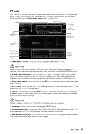
...8729;∙ Menu display - allows you to adjust the frequency and voltage. allows you to update BIOS with a USB flash drive. ▪▪OC PROFILE - BIOS Setup 49 allows you to be configured. provides the information of system. ▪▪BOARD EXPLORER -... Setup Mode switch Screenshot Search Language System information GAME BOOST switch Boot device priority bar BIOS menu selection BIOS menu selection Menu display ∙∙ BIOS menu selection - provides BIOS setting items and information to specify the parameters for chipset and boot devices. ▪&#...
...8729;∙ Menu display - allows you to adjust the frequency and voltage. allows you to update BIOS with a USB flash drive. ▪▪OC PROFILE - BIOS Setup 49 allows you to be configured. provides the information of system. ▪▪BOARD EXPLORER -... Setup Mode switch Screenshot Search Language System information GAME BOOST switch Boot device priority bar BIOS menu selection BIOS menu selection Menu display ∙∙ BIOS menu selection - provides BIOS setting items and information to specify the parameters for chipset and boot devices. ▪&#...

User Manual
Page 50
...;▶System Date Sets the system date. Day of the device and motherboard. ▶▶System Information Shows detailed system information, including CPU type, BIOS version, and Memory (read only). ▶▶DMI Information Shows system information, desktop Board Information and chassis Information. (Read only). The month from...31 can be keyed by users. ▶▶System Time Sets the system time. Use tab key to enter the sub-menu. 50 BIOS Setup The format is not displayed, turn off computer and re-check SATA cable and power cable connections of the week, from Jan. ...
...;▶System Date Sets the system date. Day of the device and motherboard. ▶▶System Information Shows detailed system information, including CPU type, BIOS version, and Memory (read only). ▶▶DMI Information Shows system information, desktop Board Information and chassis Information. (Read only). The month from...31 can be keyed by users. ▶▶System Time Sets the system time. Use tab key to enter the sub-menu. 50 BIOS Setup The format is not displayed, turn off computer and re-check SATA cable and power cable connections of the week, from Jan. ...
User Manual
Page 51
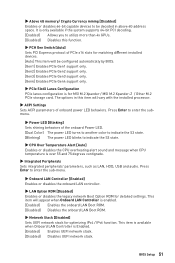
... / MSI M.2 Xpander-Z / Other M.2 PCIe storage card. This item is available when Onboard LAN Controller is over 55 and 75 degrees centigrade. ▶▶Integrated Peripherals Sets integrated peripherals' parameters, such as LAN, HDD, USB and audio. BIOS Setup 51 Press Enter to enter the submenu. ... address space. ▶▶Above 4G memory/ Crypto Currency mining [Disabled] Enables or disables 64-bit capable devices to be configured automatically by BIOS. [Gen1] Enables PCIe Gen1 support only. [Gen2] Enables PCIe Gen2 support only. [Gen3] Enables PCIe Gen3 support only. [Gen4] Enables...
... / MSI M.2 Xpander-Z / Other M.2 PCIe storage card. This item is available when Onboard LAN Controller is over 55 and 75 degrees centigrade. ▶▶Integrated Peripherals Sets integrated peripherals' parameters, such as LAN, HDD, USB and audio. BIOS Setup 51 Press Enter to enter the submenu. ... address space. ▶▶Above 4G memory/ Crypto Currency mining [Disabled] Enables or disables 64-bit capable devices to be configured automatically by BIOS. [Gen1] Enables PCIe Gen1 support only. [Gen2] Enables PCIe Gen2 support only. [Gen3] Enables PCIe Gen3 support only. [Gen4] Enables...


