User Manual
Page 1
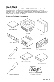
... link to install your phone or tablet. Some of Screws Quick Start 1 Preparing Tools and Components AMD® AM4 CPU CPU Fan DDR4 Memory Power Supply Unit Chassis Graphics Card Thermal Paste SATA Hard Disk Drive SATA DVD Drive Phillips Screwdriver A Package of the installations also provide video demonstrations. Please link to the URL to watch it with the web browser on your computer. Quick Start Thank you for purchasing the MSI® MAG X570 TOMAHAWK WIFI motherboard.
... link to install your phone or tablet. Some of Screws Quick Start 1 Preparing Tools and Components AMD® AM4 CPU CPU Fan DDR4 Memory Power Supply Unit Chassis Graphics Card Thermal Paste SATA Hard Disk Drive SATA DVD Drive Phillips Screwdriver A Package of the installations also provide video demonstrations. Please link to the URL to watch it with the web browser on your computer. Quick Start Thank you for purchasing the MSI® MAG X570 TOMAHAWK WIFI motherboard.

User Manual
Page 13
...Information 2 Installing a Processor 3 Installing DDR4 memory 5 Connecting the Front Panel Header 6 Installing the Motherboard 7 Connecting the Power Connectors 8 Installing SATA Drives 9 Installing a Graphics Card 10 Connecting Peripheral Devices 11 Power On...12 Specifications...15 Package contents 21 Block Diagram ...22 Rear I/O Panel ...23 LAN Port LED Status Table 23 Audio Ports Configuration 23 Realtek Audio Console 24 Overview of Components 27 CPU Socket ...29 DIMM Slots...30 PCI_E1~4: PCIe Expansion Slots 31 M2_1~2: M.2 Slots (Key M 32 SATA1~6: SATA 6Gb/s Connectors 34...
...Information 2 Installing a Processor 3 Installing DDR4 memory 5 Connecting the Front Panel Header 6 Installing the Motherboard 7 Connecting the Power Connectors 8 Installing SATA Drives 9 Installing a Graphics Card 10 Connecting Peripheral Devices 11 Power On...12 Specifications...15 Package contents 21 Block Diagram ...22 Rear I/O Panel ...23 LAN Port LED Status Table 23 Audio Ports Configuration 23 Realtek Audio Console 24 Overview of Components 27 CPU Socket ...29 DIMM Slots...30 PCI_E1~4: PCIe Expansion Slots 31 M2_1~2: M.2 Slots (Key M 32 SATA1~6: SATA 6Gb/s Connectors 34...

User Manual
Page 14
...~2: Addressable RGB LED connectors 42 Installing OS, Drivers & Utilities 43 Installing Windows® 10 43 Installing Drivers 43 Installing Utilities 43 BIOS Setup ...44 Entering BIOS Setup 44 Resetting BIOS...45 Updating BIOS...45 EZ Mode ...47 Advanced Mode ...49 SETTINGS...50 Advanced...50 Boot...55 Security ...56 Save & Exit...57 OC...58 M-FLASH ...62 OC PROFILE ...63 HARDWARE MONITOR 64 AMD RAID Configuration 65 Enabling RAIDXpert2 Configuration Utility 65 Initializing Disks 66 Creating Arrays...67 Deleting Arrays ...68 Installing RAID Driver 69 Troubleshooting 70 14 Contents
...~2: Addressable RGB LED connectors 42 Installing OS, Drivers & Utilities 43 Installing Windows® 10 43 Installing Drivers 43 Installing Utilities 43 BIOS Setup ...44 Entering BIOS Setup 44 Resetting BIOS...45 Updating BIOS...45 EZ Mode ...47 Advanced Mode ...49 SETTINGS...50 Advanced...50 Boot...55 Security ...56 Save & Exit...57 OC...58 M-FLASH ...62 OC PROFILE ...63 HARDWARE MONITOR 64 AMD RAID Configuration 65 Enabling RAIDXpert2 Configuration Utility 65 Initializing Disks 66 Creating Arrays...67 Deleting Arrays ...68 Installing RAID Driver 69 Troubleshooting 70 14 Contents

User Manual
Page 15
...;∙Supports 2DPC 2R max speed 3600 MHZ ∙∙Dual channel memory architecture ∙∙Supports non-ECC UDIMM memory ∙∙Supports ECC UDIMM memory (non-ECC mode) ∙∙Supports un-buffered memory * Please refer www.msi.com for more information on compatible memory. ∙∙1x PCIe 4.0/ 3.0 x16 slot (PCI_E1) ▪▪3rd Gen AMD Ryzen™ support PCIe 4.0 x16 mode ▪▪2nd Gen AMD Ryzen™ support PCIe 3.0 x16 mode...
...;∙Supports 2DPC 2R max speed 3600 MHZ ∙∙Dual channel memory architecture ∙∙Supports non-ECC UDIMM memory ∙∙Supports ECC UDIMM memory (non-ECC mode) ∙∙Supports un-buffered memory * Please refer www.msi.com for more information on compatible memory. ∙∙1x PCIe 4.0/ 3.0 x16 slot (PCI_E1) ▪▪3rd Gen AMD Ryzen™ support PCIe 4.0 x16 mode ▪▪2nd Gen AMD Ryzen™ support PCIe 3.0 x16 mode...

User Manual
Page 17
... Monitor USB Back Panel Connectors ∙∙CPU/ System/ Chipset temperature detection ∙∙CPU/ System/ Chipset fan speed detection ∙∙CPU/ System/ Chipset fan speed control ∙∙AMD® X570 Chipset ▪▪3x USB 3.2 Gen 2 10Gbps ports (2 Type-A ports on the back panel, 1 Type-C internal connector) ▪▪4x USB 3.2 Gen 1 5Gbps ports available through the internal USB 3.2 Gen 1 5Gbps connectors ▪▪6x USB 2.0 ports (2 Type-A ports on the back panel, 4 ports available through the internal USB 2.0 connectors) ∙∙AMD...
... Monitor USB Back Panel Connectors ∙∙CPU/ System/ Chipset temperature detection ∙∙CPU/ System/ Chipset fan speed detection ∙∙CPU/ System/ Chipset fan speed control ∙∙AMD® X570 Chipset ▪▪3x USB 3.2 Gen 2 10Gbps ports (2 Type-A ports on the back panel, 1 Type-C internal connector) ▪▪4x USB 3.2 Gen 1 5Gbps ports available through the internal USB 3.2 Gen 1 5Gbps connectors ▪▪6x USB 2.0 ports (2 Type-A ports on the back panel, 4 ports available through the internal USB 2.0 connectors) ∙∙AMD...

User Manual
Page 42
... power cord from the power outlet before installing or removing the RGB LED strip. ∙∙Please use MSI's software to control the extended LED strip. 42 Overview of LED strips. JRAINBOW1~2: Addressable RGB LED connectors The JRAINBOW connectors allow you to connect the WS2812B Individually Addressable RGB LED strips 5V. 1 1 +5V 2 3 No Pin 4 Data Ground Addressable RGB LED Strip Connection 1 +5V D JRAINBOW connector Rainbow RGB LED extension cable (optional) Addressable RGB LED Fan Connection JRAINBOW connector...
... power cord from the power outlet before installing or removing the RGB LED strip. ∙∙Please use MSI's software to control the extended LED strip. 42 Overview of LED strips. JRAINBOW1~2: Addressable RGB LED connectors The JRAINBOW connectors allow you to connect the WS2812B Individually Addressable RGB LED strips 5V. 1 1 +5V 2 3 No Pin 4 Data Ground Addressable RGB LED Strip Connection 1 +5V D JRAINBOW connector Rainbow RGB LED extension cable (optional) Addressable RGB LED Fan Connection JRAINBOW connector...

User Manual
Page 43
... the installer. If you turn off the AutoPlay feature from the Windows Control Panel, you can still manually execute the DVDSetup.exe from the Boot Menu. 6. The drivers installation will then be in progress, after it has finished it will prompt you want to get into Boot Menu. 5. Installing Utilities Before you install utilities, you to finish. 7. Click OK button to restart. 7. Press F11 key during the computer POST (Power...
... the installer. If you turn off the AutoPlay feature from the Windows Control Panel, you can still manually execute the DVDSetup.exe from the Boot Menu. 6. The drivers installation will then be in progress, after it has finished it will prompt you want to get into Boot Menu. 5. Installing Utilities Before you install utilities, you to finish. 7. Click OK button to restart. 7. Press F11 key during the computer POST (Power...
User Manual
Page 45
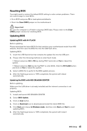
... BIOS with M-FLASH Before updating: Please download the latest BIOS file that contains the update file into the USB flash drive. Resetting BIOS You might need to restore the default BIOS setting to solve certain problems. There are several ways to reset BIOS: ∙∙Go to BIOS and press F6 to perform the BIOS update process. 4. Updating BIOS Updating BIOS with MSI DRAGON CENTER Before updating: Make sure the LAN driver is already installed and the internet connection is off before clearing CMOS...
... BIOS with M-FLASH Before updating: Please download the latest BIOS file that contains the update file into the USB flash drive. Resetting BIOS You might need to restore the default BIOS setting to solve certain problems. There are several ways to reset BIOS: ∙∙Go to BIOS and press F6 to perform the BIOS update process. 4. Updating BIOS Updating BIOS with MSI DRAGON CENTER Before updating: Make sure the LAN driver is already installed and the internet connection is off before clearing CMOS...
User Manual
Page 46
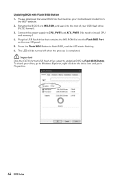
... flash BIOS, and the LED starts flashing. 6. Press the Flash BIOS Button to install CPU and memory.) 4. To check your motherboard model from the MSI® website. 2. The LED will be turned off when the process is completed. ⚠⚠Important Only the FAT32 format USB flash drive supports updating BIOS by Flash BIOS Button. Plug the USB flash drive that matches your drive, go to the root of your USB flash drive (FAT32 format). 3. Please download the latest BIOS file that contains the MSI.ROM file into the Flash BIOS Port...
... flash BIOS, and the LED starts flashing. 6. Press the Flash BIOS Button to install CPU and memory.) 4. To check your motherboard model from the MSI® website. 2. The LED will be turned off when the process is completed. ⚠⚠Important Only the FAT32 format USB flash drive supports updating BIOS by Flash BIOS Button. Plug the USB flash drive that matches your drive, go to the root of your USB flash drive (FAT32 format). 3. Please download the latest BIOS file that contains the MSI.ROM file into the Flash BIOS Port...
User Manual
Page 47
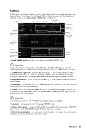
.... ∙∙ Language - BIOS Setup 47 A-XMP switch Setup Mode switch Screenshot Search Language System information GAME BOOST switch Boot device priority bar Information display M-Flash Favorites Hardware Monitor Function buttons ∙∙ GAME BOOST switch - shows the CPU/ DDR speed, CPU/ MB temperature, MB/ CPU type, memory size, CPU/ DDR voltage, BIOS version and build date. ∙∙ Boot device priority bar - click on this tab or the F7 key to switch between Advanced mode and EZ mode. ∙∙ Screenshot...
.... ∙∙ Language - BIOS Setup 47 A-XMP switch Setup Mode switch Screenshot Search Language System information GAME BOOST switch Boot device priority bar Information display M-Flash Favorites Hardware Monitor Function buttons ∙∙ GAME BOOST switch - shows the CPU/ DDR speed, CPU/ MB temperature, MB/ CPU type, memory size, CPU/ DDR voltage, BIOS version and build date. ∙∙ Boot device priority bar - click on this tab or the F7 key to switch between Advanced mode and EZ mode. ∙∙ Screenshot...
User Manual
Page 48
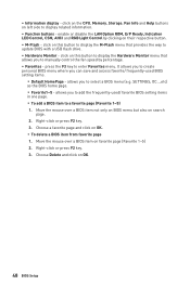
... BIOS setting items in one page. ▪▪To add a BIOS item to manually control the fan speed by clicking on OK. ▪▪To delete a BIOS item from favorite page 1. Move the mouse over a BIOS item not only on BIOS menu but also on this button to display the Hardware Monitor menu that provides the way to select a BIOS menu (e.g. enable or disable the LAN Option ROM, ErP Ready, Indication LED Control, CSM, AHCI...
... BIOS setting items in one page. ▪▪To add a BIOS item to manually control the fan speed by clicking on OK. ▪▪To delete a BIOS item from favorite page 1. Move the mouse over a BIOS item not only on BIOS menu but also on this button to display the Hardware Monitor menu that provides the way to select a BIOS menu (e.g. enable or disable the LAN Option ROM, ErP Ready, Indication LED Control, CSM, AHCI...
User Manual
Page 51
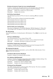
.... BIOS Setup 51 The options in above 4G address space. This item will vary with the installed processor. ▶▶ACPI Settings Sets ACPI parameters of onboard power LED behaviors. Press Enter to enter the submenu. ▶▶Power LED [Blinking] Sets shining behaviors of PCIe x16 slots for matching different installed devices. [Auto] This item will be decoded in this item will appear when Onboard LAN Controller is enabled. [Enabled] Enables the onboard LAN Boot ROM. [Disabled] Disables the onboard LAN Boot ROM. ▶▶Network Stack [Disabled] Sets UEFI network stack...
.... BIOS Setup 51 The options in above 4G address space. This item will vary with the installed processor. ▶▶ACPI Settings Sets ACPI parameters of onboard power LED behaviors. Press Enter to enter the submenu. ▶▶Power LED [Blinking] Sets shining behaviors of PCIe x16 slots for matching different installed devices. [Auto] This item will be decoded in this item will appear when Onboard LAN Controller is enabled. [Enabled] Enables the onboard LAN Boot ROM. [Disabled] Disables the onboard LAN Boot ROM. ▶▶Network Stack [Disabled] Sets UEFI network stack...
User Manual
Page 52
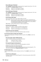
... [RAID Mode] Enables RAID function for SATA storage devices. ▶▶SATAx Hot Plug [Disabled] Allows user to enable or disable the SATA hot plug support. [Enabled] Enables hot plug support for the SATA ports. [Disabled] Disables hot plug support for the SATA ports. ▶▶HD Audio Controller [Enabled] Enables or disables the onboard High Definition Audio controller. ▶▶Integrated Graphics Configuration (optional) Adjusts integrated graphics settings for optimum system. This item will appear when Network Stack is enabled. ▶▶USB Configuration Sets...
... [RAID Mode] Enables RAID function for SATA storage devices. ▶▶SATAx Hot Plug [Disabled] Allows user to enable or disable the SATA hot plug support. [Enabled] Enables hot plug support for the SATA ports. [Disabled] Disables hot plug support for the SATA ports. ▶▶HD Audio Controller [Enabled] Enables or disables the onboard High Definition Audio controller. ▶▶Integrated Graphics Configuration (optional) Adjusts integrated graphics settings for optimum system. This item will appear when Network Stack is enabled. ▶▶USB Configuration Sets...
User Manual
Page 53
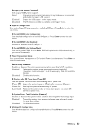
.... It will not support S4 & S5 wake up by USB, PCI and PCIe devices. [Disabled] Disables this function. ▶▶Windows OS Configuration Sets Windows detailed configuration and behaviors. BIOS Setup 53 Press Enter to Auto, BIOS will be unavailable under legacy mode. ▶▶Super IO Configuration Sets system Super I/O chip parameters including COM port. If set it manually. ▶▶Power Management Setup Sets system Power Management of serial(COM) port x. ▶▶Legacy USB Support [Enabled] Sets Legacy USB function support. [Auto] The system will...
.... It will not support S4 & S5 wake up by USB, PCI and PCIe devices. [Disabled] Disables this function. ▶▶Windows OS Configuration Sets Windows detailed configuration and behaviors. BIOS Setup 53 Press Enter to Auto, BIOS will be unavailable under legacy mode. ▶▶Super IO Configuration Sets system Super I/O chip parameters including COM port. If set it manually. ▶▶Power Management Setup Sets system Power Management of serial(COM) port x. ▶▶Legacy USB Support [Enabled] Sets Legacy USB function support. [Auto] The system will...
User Manual
Page 54
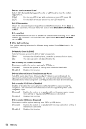
... the power saving modes when activity or input signal of PCIe device is detected. [Disabled] Disables this function. ▶▶Resume by USB Device [Disabled] Disables or enables system wake up from sleep state when activity of USB device is set wake up on devices and UEFI mode OS. ▶▶GOP Information Shows the onboard Graphics Output Protocol (GOP) information. Press Enter to boot up events of installed PCI-E expansion cards, integrated LAN controllers or USB devices which are supported by...
... the power saving modes when activity or input signal of PCIe device is detected. [Disabled] Disables this function. ▶▶Resume by USB Device [Disabled] Disables or enables system wake up from sleep state when activity of USB device is set wake up on devices and UEFI mode OS. ▶▶GOP Information Shows the onboard Graphics Output Protocol (GOP) information. Press Enter to boot up events of installed PCI-E expansion cards, integrated LAN controllers or USB devices which are supported by...
User Manual
Page 57
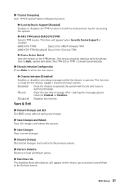
...;Restore Defaults Restore or load all default values. ▶▶Boot Override The installed boot-able devices will detect the TPM 2.0 or TPM 1.2 model automatically. ▶▶Chassis Intrusion Configuration Press Enter to enter the sub-menu. ▶▶Chassis Intrusion [Disabled] Enables or disables recording messages while the chassis is opened , the system will appear when Security Device Support is opened . This item will record and issue a warning message. [Reset] Clear...
...;Restore Defaults Restore or load all default values. ▶▶Boot Override The installed boot-able devices will detect the TPM 2.0 or TPM 1.2 model automatically. ▶▶Chassis Intrusion Configuration Press Enter to enter the sub-menu. ▶▶Chassis Intrusion [Disabled] Enables or disables recording messages while the chassis is opened , the system will appear when Security Device Support is opened . This item will record and issue a warning message. [Reset] Clear...

User Manual
Page 59
... base clock frequency. ▶▶UCLK DIV1 Mode [Auto] Sets UCLK (Internal memory controller clock) mode. ▶▶Load Memory Presets [Disabled]* Load OC Memory Preset will set these voltages automatically or you to set the voltages related to set it manually. BIOS Setup 59 If it occurs, please clear the CMOS data and restore the default settings. (Refer to the Clear CMOS jumper section to clear the CMOS data, and enter the BIOS to load the default settings.) ▶▶CPU Voltages control [Auto] These options allows you to enter the sub-menu.
... base clock frequency. ▶▶UCLK DIV1 Mode [Auto] Sets UCLK (Internal memory controller clock) mode. ▶▶Load Memory Presets [Disabled]* Load OC Memory Preset will set these voltages automatically or you to set the voltages related to set it manually. BIOS Setup 59 If it occurs, please clear the CMOS data and restore the default settings. (Refer to the Clear CMOS jumper section to clear the CMOS data, and enter the BIOS to load the default settings.) ▶▶CPU Voltages control [Auto] These options allows you to enter the sub-menu.
User Manual
Page 61
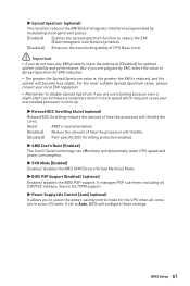
... value of time the processor will throttle. [Disabled] Part-specific EDC throttling protection enabled. ▶▶AMD Cool'n'Quiet [Enabled] The Cool'n'Quiet technology can effectively and dynamically lower CPU speed and power consumption. ▶▶SVM Mode [Enabled] Enables/ disables the AMD SVM (Secure Virtual Machine) Mode. ▶▶BIOS PSP Support [Enabled] (optional) Enables/ disables the BIOS PSP support. BIOS Setup 61 But if you do not have any EMI problem, leave the setting at [Disabled] for EMI reduction...
... value of time the processor will throttle. [Disabled] Part-specific EDC throttling protection enabled. ▶▶AMD Cool'n'Quiet [Enabled] The Cool'n'Quiet technology can effectively and dynamically lower CPU speed and power consumption. ▶▶SVM Mode [Enabled] Enables/ disables the AMD SVM (Secure Virtual Machine) Mode. ▶▶BIOS PSP Support [Enabled] (optional) Enables/ disables the BIOS PSP support. BIOS Setup 61 But if you do not have any EMI problem, leave the setting at [Disabled] for EMI reduction...
User Manual
Page 69
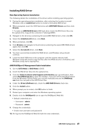
..., click OK. 6. Windows setup will need to copy the files after selecting the location to install Windows click on Load driver button to RAID Mode in BIOS 2. AMD RAIDXpert2 Management Suite Installation 1. Set the SATA Mode to install a third party RAID driver. 2. Insert the MSI Driver Disc into the optical drive. 3. Click the Install button. 6. When prompt you can still manually execute the DVDSetup. Restart your computer and enter the Windows operating system. 8. admin ▫▫Password - Change the credentials...
..., click OK. 6. Windows setup will need to copy the files after selecting the location to install Windows click on Load driver button to RAID Mode in BIOS 2. AMD RAIDXpert2 Management Suite Installation 1. Set the SATA Mode to install a third party RAID driver. 2. Insert the MSI Driver Disc into the optical drive. 3. Click the Install button. 6. When prompt you can still manually execute the DVDSetup. Restart your computer and enter the Windows operating system. 8. admin ▫▫Password - Change the credentials...

User Manual
Page 70
... network chipset driver has been installed. ∙∙Verify if the network cable is properly connected and make sure the button is turned on. ∙∙Check if the power switch cable is connected to JFP1 pin header properly. ∙∙Verify the Clear CMOS jumper JBAT1 is turned on. ∙∙Select different inputs on the motherboard rear IO panel. ∙∙Remove secondary speakers/ headphones, HDMI cables, USB audio devices. ∙∙Test with another known working graphics card...
... network chipset driver has been installed. ∙∙Verify if the network cable is properly connected and make sure the button is turned on. ∙∙Check if the power switch cable is connected to JFP1 pin header properly. ∙∙Verify the Clear CMOS jumper JBAT1 is turned on. ∙∙Select different inputs on the motherboard rear IO panel. ∙∙Remove secondary speakers/ headphones, HDMI cables, USB audio devices. ∙∙Test with another known working graphics card...


