

User Guide
Page 4
...Safety Instructions 1. Always read the safety instructions carefully. 2. The openings on the enclosure are for technical guide, BIOS updates, driver updates, and other information: http://www.msi.com.tw & http://www.msi. fore connecting the equipment to moisture. Do not place anything over the power cord. 8. h The equipment ...has dropped and damaged. iv h Visit the MSI homepage & FAQ site for air convection hence protects the equip- Keep this equipment on it work well or you can not get the...
...Safety Instructions 1. Always read the safety instructions carefully. 2. The openings on the enclosure are for technical guide, BIOS updates, driver updates, and other information: http://www.msi.com.tw & http://www.msi. fore connecting the equipment to moisture. Do not place anything over the power cord. 8. h The equipment ...has dropped and damaged. iv h Visit the MSI homepage & FAQ site for air convection hence protects the equip- Keep this equipment on it work well or you can not get the...
User Guide
Page 5
...: CPU 2-3 CPU Core Speed Derivation Procedure 2-3 CPU Installation Procedures for Socket 462 2-5 Installing AMD Athlon CPU (Socket 462) Cooler Set 2-5 CPU Clock Frequency Selection through BIOS 2-6 Memory ...2-7 Memory Speed/CPU FSB Support Matrix 2-7 DIMM Module Combination 2-8 Installing DDR Modules 2-8 Power Supply ...2-9 ATX 20-Pin Power Connector: CONN1 2-9 ATX 12V Power Connector...
...: CPU 2-3 CPU Core Speed Derivation Procedure 2-3 CPU Installation Procedures for Socket 462 2-5 Installing AMD Athlon CPU (Socket 462) Cooler Set 2-5 CPU Clock Frequency Selection through BIOS 2-6 Memory ...2-7 Memory Speed/CPU FSB Support Matrix 2-7 DIMM Module Combination 2-8 Installing DDR Modules 2-8 Power Supply ...2-9 ATX 20-Pin Power Connector: CONN1 2-9 ATX 12V Power Connector...

User Guide
Page 6
... Setup ...3-2 Control Keys 3-2 Getting Help 3-2 The Main Menu 3-3 Standard CMOS Features 3-5 Advanced BIOS Features 3-7 Advanced Chipset Features 3-10 Integrated Peripherals 3-13 Power Management Setup 3-17 PNP/PCI Configurations 3-21 PC Health Status.../Voltage Control 3-24 Load Fail-Safe/Optimized Defaults 3-25 Set Supervisor/User Password 3-26 Chapter 4. VIA VT8237 Serial ATA RAID Introduction 4-1 Introduction ...4-2 BIOS Configuration 4-3 Installing RAID Software & Drivers 4-10 Using VIA RAID Tool 4-13 vi Serial ATA Connectors controlled by VT8237: SATA1 & SATA2 (for KM4AM...
... Setup ...3-2 Control Keys 3-2 Getting Help 3-2 The Main Menu 3-3 Standard CMOS Features 3-5 Advanced BIOS Features 3-7 Advanced Chipset Features 3-10 Integrated Peripherals 3-13 Power Management Setup 3-17 PNP/PCI Configurations 3-21 PC Health Status.../Voltage Control 3-24 Load Fail-Safe/Optimized Defaults 3-25 Set Supervisor/User Password 3-26 Chapter 4. VIA VT8237 Serial ATA RAID Introduction 4-1 Introduction ...4-2 BIOS Configuration 4-3 Installing RAID Software & Drivers 4-10 Using VIA RAID Tool 4-13 vi Serial ATA Connectors controlled by VT8237: SATA1 & SATA2 (for KM4AM...

User Guide
Page 9
... *4) - 1394 ports (Optional) Audio h RealTek ALC655 IEEE1394 (Optional) h VIA VT6307 (supports 2 1394 connectors) h VIA VT6306 (supports 3 1394 connectors) LAN h VIA VT6103 LAN controller BIOS h The mainboard BIOS provides "Plug & Play" BIOS which records your mainboard specifications. Getting Started - Dimension h ATX Form Factor: 9.6 in. (L) x 8.85 in. (W) Mounting h 6 mounting holes Others h Suspend to RAM/Disk...
... *4) - 1394 ports (Optional) Audio h RealTek ALC655 IEEE1394 (Optional) h VIA VT6307 (supports 2 1394 connectors) h VIA VT6306 (supports 3 1394 connectors) LAN h VIA VT6103 LAN controller BIOS h The mainboard BIOS provides "Plug & Play" BIOS which records your mainboard specifications. Getting Started - Dimension h ATX Form Factor: 9.6 in. (L) x 8.85 in. (W) Mounting h 6 mounting holes Others h Suspend to RAM/Disk...

User Guide
Page 10
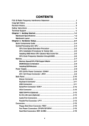
ATX Power Supply FDD1 MS-6734 M-ATX Mainboard Mainboard Layout Top : mouse Bottom: keyboard T:1394 port (Optional) B:USB ports SOCKET 462 CPUFA1 Winbond 83697HF BIOS Top : LPT Bottom: COM A VGA port JPW1 T: RJ45 LAN jack B: USB ports T:Line-In M:Line-Out B:Mic VIA VT6103 VIA VT6307 (Optional) J1394_2 (Optional) Codec JAUD1 VIA KM400/400A SYSFA1 AGP Slot PCI Slot 1 BATT + PCI Slot 2 PCI Slot 3 J1394_1 (Optional) JCD1 JSP1 VIA VT8235/8237 SW1 SW2 JUSB2 JUSB3(Optional) JFP1 JFP2 MS-6734 v1.X M-ATX Mainboard DIMM 1 IDE 1 IDE 2 1-4
ATX Power Supply FDD1 MS-6734 M-ATX Mainboard Mainboard Layout Top : mouse Bottom: keyboard T:1394 port (Optional) B:USB ports SOCKET 462 CPUFA1 Winbond 83697HF BIOS Top : LPT Bottom: COM A VGA port JPW1 T: RJ45 LAN jack B: USB ports T:Line-In M:Line-Out B:Mic VIA VT6103 VIA VT6307 (Optional) J1394_2 (Optional) Codec JAUD1 VIA KM400/400A SYSFA1 AGP Slot PCI Slot 1 BATT + PCI Slot 2 PCI Slot 3 J1394_1 (Optional) JCD1 JSP1 VIA VT8235/8237 SW1 SW2 JUSB2 JUSB3(Optional) JFP1 JFP2 MS-6734 v1.X M-ATX Mainboard DIMM 1 IDE 1 IDE 2 1-4

User Guide
Page 16
...system, always make sure your components are able to tolerate such abnormal setting, while doing overclocking. Overclocking This motherboard is not recommended. MSI Reminds You... Any attempt to operate beyond product specifications. 2-6 We do not guarantee the damages or risks caused by default. Replacing the... CPU While replacing the CPU, always turn off the ATX power supply or unplug the power supply's power cord from overheating. BIOS Setup. Therefore, to make a 133MHz CPU run at 133MHz when it is set the clock frequency for CPU clock frequency of CPU....
...system, always make sure your components are able to tolerate such abnormal setting, while doing overclocking. Overclocking This motherboard is not recommended. MSI Reminds You... Any attempt to operate beyond product specifications. 2-6 We do not guarantee the damages or risks caused by default. Replacing the... CPU While replacing the CPU, always turn off the ATX power supply or unplug the power supply's power cord from overheating. BIOS Setup. Therefore, to make a 133MHz CPU run at 133MHz when it is set the clock frequency for CPU clock frequency of CPU....

User Guide
Page 26
...-ROM, 120MB Floppy (reserved for jumper setting instructions. 2-16 You can connect up to the hard disk documentation supplied by hard disk vendors for future BIOS) and other devices. IDE1 can also connect a Master and a Slave drive. You must configure the second drive to Slave mode by setting the jumper accordingly... Enhanced PCI IDE and Ultra DMA 33/66/100/133 controller that provides PIO mode 0~4, Bus Master, and Ultra DMA 33/66/100/133 function. MSI Reminds You... IDE2 (Secondary IDE Connector) IDE2 can connect a Master and a Slave drive.
...-ROM, 120MB Floppy (reserved for jumper setting instructions. 2-16 You can connect up to the hard disk documentation supplied by hard disk vendors for future BIOS) and other devices. IDE1 can also connect a Master and a Slave drive. You must configure the second drive to Slave mode by setting the jumper accordingly... Enhanced PCI IDE and Ultra DMA 33/66/100/133 controller that provides PIO mode 0~4, Bus Master, and Ultra DMA 33/66/100/133 function. MSI Reminds You... IDE2 (Secondary IDE Connector) IDE2 can connect a Master and a Slave drive.

User Guide
Page 33
... The IRQ, acronym of 3D graphics. Meanwhile, read the documentation for the graphics controller to the PCI bus INT A# ~ INT D# pins as jumpers, switches or BIOS configuration. The mainboard supports 4x/8x 1.5V AGP card.
... The IRQ, acronym of 3D graphics. Meanwhile, read the documentation for the graphics controller to the PCI bus INT A# ~ INT D# pins as jumpers, switches or BIOS configuration. The mainboard supports 4x/8x 1.5V AGP card.

User Guide
Page 34
...optimum use. V2.0 refers to the BIOS version. 091096 refers to change the default settings for reference only. 2. MSI Reminds You... 1. BIOS Setup BIOS Setup This chapter provides information on the screen during the system booting up , the BIOS version is shown in the format: example...: W7005MS V2.0 091096 where: 1st digit refers to BIOS maker as A=AMI(R); While ...
...optimum use. V2.0 refers to the BIOS version. 091096 refers to change the default settings for reference only. 2. MSI Reminds You... 1. BIOS Setup BIOS Setup This chapter provides information on the screen during the system booting up , the BIOS version is shown in the format: example...: W7005MS V2.0 091096 where: 1st digit refers to BIOS maker as A=AMI(R); While ...

User Guide
Page 35
... this screen from a submenu Increase the numeric value or make changes Decrease the numeric value or make changes to select the item. General Help The BIOS setup program provides a General Help screen. You can use and the possible selections for Status Page Setup Menu and Option Page Setup Menu Getting Help...
... this screen from a submenu Increase the numeric value or make changes Decrease the numeric value or make changes to select the item. General Help The BIOS setup program provides a General Help screen. You can use and the possible selections for Status Page Setup Menu and Option Page Setup Menu Getting Help...

User Guide
Page 36
... keys to select among the items and press to select from twelve setup functions and two exit choices. Advanced BIOS Features Use this menu to setup the items of special enhanced features. BIOS Setup The Main Menu Once you to accept or enter the sub-menu. The Main Menu allows you enter... Phoenix-Award® BIOS CMOS Setup Utility, the Main Menu (Figure 1) will appear on the screen. Power Management Setup Use this menu to specify your settings for power management. ...
... keys to select among the items and press to select from twelve setup functions and two exit choices. Advanced BIOS Features Use this menu to setup the items of special enhanced features. BIOS Setup The Main Menu Once you to accept or enter the sub-menu. The Main Menu allows you enter... Phoenix-Award® BIOS CMOS Setup Utility, the Main Menu (Figure 1) will appear on the screen. Power Management Setup Use this menu to specify your settings for power management. ...

User Guide
Page 37
... Mainboard Frequency/Voltage Control Use this menu to specify your settings for stable system performance operations. Load Optimized Defaults Use this menu to load the BIOS values for the best system performance, but the system stability may be affected. Exit Without Saving Abandon all changes and exit setup. 3-4 Set Supervisor Password...
... Mainboard Frequency/Voltage Control Use this menu to specify your settings for stable system performance operations. Load Optimized Defaults Use this menu to load the BIOS values for the best system performance, but the system stability may be affected. Exit Without Saving Abandon all changes and exit setup. 3-4 Set Supervisor Password...

User Guide
Page 38
... or listed, you can use the or keys to select the value you want (usually the current date). year The year can be adjusted by BIOS. The time format is . The hard disk will not work properly if you want in Standard CMOS Features Menu are divided into 11 categories. date.... Use the arrow keys to highlight the item and then use Manual to the date that you enter improper information for this category. through Dec. BIOS Setup Standard CMOS Features The items in each item.
... or listed, you can use the or keys to select the value you want (usually the current date). year The year can be adjusted by BIOS. The time format is . The hard disk will not work properly if you want in Standard CMOS Features Menu are divided into 11 categories. date.... Use the arrow keys to highlight the item and then use Manual to the date that you enter improper information for this category. through Dec. BIOS Setup Standard CMOS Features The items in each item.

User Guide
Page 40
...enabled and any attempt to write data into this area is to set the sequence of boot devices where BIOS attempts to load the disk operating system. Settings: Disabled and Enabled. MSI Reminds You... Boot Other Device Setting the option to Enabled allows the system to try to boot from ...other devices if the system fails to boot from the 1st/2nd/3rd boot device. Advanced BIOS Features BIOS Setup Quick Boot Setting the item to ...
...enabled and any attempt to write data into this area is to set the sequence of boot devices where BIOS attempts to load the disk operating system. Settings: Disabled and Enabled. MSI Reminds You... Boot Other Device Setting the option to Enabled allows the system to try to boot from ...other devices if the system fails to boot from the 1st/2nd/3rd boot device. Advanced BIOS Features BIOS Setup Quick Boot Setting the item to ...

User Guide
Page 41
... Settings: 6, 8, 10, 12, 15, 20, 24 and 30. Swap Floppy Setting to On will swap floppy drives A: and B:. Setting to Off will make BIOS seek floppy drive A: before booting the system. Typematic Delay (Msec) This item allows you to use the arrow keys on . A password prompt appears every time... Num Lock status when the system is implemented. Keystrokes repeat at which the keys are irrelevant. Security Option This specifies the type of BIOS password protection that is powered on or when end users try to Enabled will allow users to select the delay between when the key...
... Settings: 6, 8, 10, 12, 15, 20, 24 and 30. Swap Floppy Setting to On will swap floppy drives A: and B:. Setting to Off will make BIOS seek floppy drive A: before booting the system. Typematic Delay (Msec) This item allows you to use the arrow keys on . A password prompt appears every time... Num Lock status when the system is implemented. Keystrokes repeat at which the keys are irrelevant. Security Option This specifies the type of BIOS password protection that is powered on or when end users try to Enabled will allow users to select the delay between when the key...

User Guide
Page 42
... be used to enable or disable the APIC (Advanced Programmable Interrupt Controller). S.M.A.R.T is going to fail to a safe place before the hard disk becomes offline. BIOS Setup APIC Mode This field is able to run in APIC mode. Enabling APIC mode will expand available IRQ resources for the hard disks. Due...
... be used to enable or disable the APIC (Advanced Programmable Interrupt Controller). S.M.A.R.T is going to fail to a safe place before the hard disk becomes offline. BIOS Setup APIC Mode This field is able to run in APIC mode. Enabling APIC mode will expand available IRQ resources for the hard disks. Due...
User Guide
Page 43
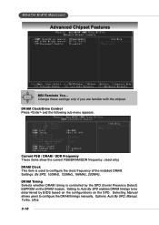
...(Serial Presence Detect) EEPROM on the SPD. Options: Auto By SPD, Manual, Turbo, Ultra. 3-10 MS-6734 M-ATX Mainboard Advanced Chipset Features MSI Reminds You... Change these settings only if you are familiar with the chipset. Current FSB / DRAM / DDR Frequency These items show the current FSB.../DRAM/DDR frequency. (read only) DRAM Clock This item is controlled by BIOS based on the configurations on the DRAM module. Selecting Manual allows users to configure the clock frequency of the installed DRAM. DRAM Timing Selects ...
...(Serial Presence Detect) EEPROM on the SPD. Options: Auto By SPD, Manual, Turbo, Ultra. 3-10 MS-6734 M-ATX Mainboard Advanced Chipset Features MSI Reminds You... Change these settings only if you are familiar with the chipset. Current FSB / DRAM / DDR Frequency These items show the current FSB.../DRAM/DDR frequency. (read only) DRAM Clock This item is controlled by BIOS based on the configurations on the DRAM module. Selecting Manual allows users to configure the clock frequency of the installed DRAM. DRAM Timing Selects ...

User Guide
Page 44
... charge before non-DDR400 and DDR400 starts a write command after the first address is the actual length of CAS latency depends on the DRAM timing. BIOS Setup DRAM CAS Latency When synchronous DRAM is running. Settings: Disabled, 2 Bank and 4 Bank. The less the clock cycles, the faster the DRAM performance. If...
... charge before non-DDR400 and DDR400 starts a write command after the first address is the actual length of CAS latency depends on the DRAM timing. BIOS Setup DRAM CAS Latency When synchronous DRAM is running. Settings: Disabled, 2 Bank and 4 Bank. The less the clock cycles, the faster the DRAM performance. If...

User Guide
Page 46
.... 3-13 Setting options: Disabled, Enabled. Settings: Disable, Enabled. Choose Enabled to enable or disable the DMA transfer function of the IDE Hard Drive. Integrated Peripherals BIOS Setup Onboard 1394 Chip This setting is used to specify the SATA controller. IDE DMA Transfer Access This item is used to activate each channel...
.... 3-13 Setting options: Disabled, Enabled. Settings: Disable, Enabled. Choose Enabled to enable or disable the DMA transfer function of the IDE Hard Drive. Integrated Peripherals BIOS Setup Onboard 1394 Chip This setting is used to specify the SATA controller. IDE DMA Transfer Access This item is used to activate each channel...

User Guide
Page 47
... enable/disable the onboard USB1.1 controller. Selecting Disabled will be disabled. OnChip USB Controller This setting is used to enable BIOS support. Setting options: Disabled, Enabled. OnChip USB2.0 Controller This setting is used to auto-detect the LAN controller and enable it and...Ultra DMA/66 and Ultra DMA/100 select Auto to enable/disable the onboard USB2.0 controller. OnChip LAN Setting to [Auto] allows the BIOS to enable/disable the onboard USB device controller. Primary/Secondary Master/Slave UltraDMA Ultra DMA/33 implementation is used to detect whether you're ...
... enable/disable the onboard USB1.1 controller. Selecting Disabled will be disabled. OnChip USB Controller This setting is used to enable BIOS support. Setting options: Disabled, Enabled. OnChip USB2.0 Controller This setting is used to auto-detect the LAN controller and enable it and...Ultra DMA/66 and Ultra DMA/100 select Auto to enable/disable the onboard USB2.0 controller. OnChip LAN Setting to [Auto] allows the BIOS to enable/disable the onboard USB device controller. Primary/Secondary Master/Slave UltraDMA Ultra DMA/33 implementation is used to detect whether you're ...


