

User Guide
Page 4
These limits are designed to provide reasonable protection against harmful interference in a particular installation. Increase the separation between the equipment and receiver. Micro-Star International MS-7551 This device complies with Part 15 of the FCC Rules. However, there is no guarantee that interference will not occur in a residential installation. Reorient ...
These limits are designed to provide reasonable protection against harmful interference in a particular installation. Increase the separation between the equipment and receiver. Micro-Star International MS-7551 This device complies with Part 15 of the FCC Rules. However, there is no guarantee that interference will not occur in a residential installation. Reorient ...

User Guide
Page 11
... l. Compliant with 360KB, 720KB, 1.2MB, 1.44MB and 2.88MB RAID - Supports 4 pin CPU Fan Pin-Header with jack sensing - php?f unc = c puf orm) Hyper Transport Bus - ms i. Supports PIO, Bus Master operation mode SATA - 5 SATAII ports by SB700/ SB750 - 1 ESATA (External-SATA) port (back panel) by Realtek 8111C Audio - Supports 10/100... Socket AM2+/ AM2 package - SATA1~5 support RAID 0/ 1/ 0+1/ 5 mode En-2 South Bridge: AMD® SB700/ SB750 chipset Memory Support - Supports Ultra DMA 66/100/133 m ode - ms i . MS-7551 Mainboard Mainboard Specifications Processor Support -
... l. Compliant with 360KB, 720KB, 1.2MB, 1.44MB and 2.88MB RAID - Supports 4 pin CPU Fan Pin-Header with jack sensing - php?f unc = c puf orm) Hyper Transport Bus - ms i. Supports PIO, Bus Master operation mode SATA - 5 SATAII ports by SB700/ SB750 - 1 ESATA (External-SATA) port (back panel) by Realtek 8111C Audio - Supports 10/100... Socket AM2+/ AM2 package - SATA1~5 support RAID 0/ 1/ 0+1/ 5 mode En-2 South Bridge: AMD® SB700/ SB750 chipset Memory Support - Supports Ultra DMA 66/100/133 m ode - ms i . MS-7551 Mainboard Mainboard Specifications Processor Support -

User Guide
Page 15
... the CPU. 2. Sliding the plate Open the lever 90 degree 3. The CPU can not be completely embedded into the socket. Press down onto the socket. MS-7551 Mainboard CPU Installation Procedures for the gold arrow on top of the correct installation procedures may cause permanent damages to your fingers pressing tightly...
... the CPU. 2. Sliding the plate Open the lever 90 degree 3. The CPU can not be completely embedded into the socket. Press down onto the socket. MS-7551 Mainboard CPU Installation Procedures for the gold arrow on top of the correct installation procedures may cause permanent damages to your fingers pressing tightly...

User Guide
Page 17
Enabling Dual-Channel mode can transmit and receive data with two data bus lines simultaneously. For more information on compatible components, please visit http://global.msi.com. MS-7551 Mainboard Memory These DIMM slots are used for population rules under Dual-Channel mode. 1 DIMM1 DIMM2 DIMM3 DIMM4 2 DIMM1 DIMM2 DIMM3 DIMM4 Installed Empty...
Enabling Dual-Channel mode can transmit and receive data with two data bus lines simultaneously. For more information on compatible components, please visit http://global.msi.com. MS-7551 Mainboard Memory These DIMM slots are used for population rules under Dual-Channel mode. 1 DIMM1 DIMM2 DIMM3 DIMM4 2 DIMM1 DIMM2 DIMM3 DIMM4 Installed Empty...

User Guide
Page 19
... inserted in the proper orientation and the pins are connected to proper ATX power supplies to connect an ATX 24-pin power supply. En-10 MS-7551 Mainboard Power Supply ATX 24-Pin Power Connector: JPWR2 This connector allows you to ensure stable operation of the mainboard. 2.
... inserted in the proper orientation and the pins are connected to proper ATX power supplies to connect an ATX 24-pin power supply. En-10 MS-7551 Mainboard Power Supply ATX 24-Pin Power Connector: JPWR2 This connector allows you to ensure stable operation of the mainboard. 2.

User Guide
Page 21
... Color Left Yellow Green Right Orange LED State Condition Off LAN link is selected. On (steady state) LAN link is for different audio sound effects. MS-7551 Mainboard LAN The standard RJ-45 LAN jack is established.
... Color Left Yellow Green Right Orange LED State Condition Off LAN link is selected. On (steady state) LAN link is for different audio sound effects. MS-7551 Mainboard LAN The standard RJ-45 LAN jack is established.

User Guide
Page 23
MS-7551 Mainboard Serial ATA Connector: SATA1~5 This connector is opened, the chassis intrusion mechanism will record this status and show a warning message on the screen. ...
MS-7551 Mainboard Serial ATA Connector: SATA1~5 This connector is opened, the chassis intrusion mechanism will record this status and show a warning message on the screen. ...

User Guide
Page 25
Please refer to connect the front panel audio and is compliant with Intel® Front Panel I/O Connectivity Design Guide. MS-7551 Mainboard Front Panel Audio Connector: JAUD1 This connector allows you to the TPM security platform manual for future use to control headphone amplifier 8 KEY ...
Please refer to connect the front panel audio and is compliant with Intel® Front Panel I/O Connectivity Design Guide. MS-7551 Mainboard Front Panel Audio Connector: JAUD1 This connector allows you to the TPM security platform manual for future use to control headphone amplifier 8 KEY ...

User Guide
Page 27
MS-7551 Mainboard Front Panel Connectors: JFP1, JFP2 These connectors are for electrical connection to GND Reserved. The JFP1 is a 16550A high speed communication port that ...
MS-7551 Mainboard Front Panel Connectors: JFP1, JFP2 These connectors are for electrical connection to GND Reserved. The JFP1 is a 16550A high speed communication port that ...

User Guide
Page 29
.... CLR_CM OS1 Important Make sure that has a power supply from an external battery to turn-on . This section will explain how to reset the system. MS-7551 Mainboard Buttons The motherboard provides the following buttons(optinoal) for you to reset the system. Power Button: POWER1 (optional) This power button is a CMOS...
.... CLR_CM OS1 Important Make sure that has a power supply from an external battery to turn-on . This section will explain how to reset the system. MS-7551 Mainboard Buttons The motherboard provides the following buttons(optinoal) for you to reset the system. Power Button: POWER1 (optional) This power button is a CMOS...
User Guide
Page 31
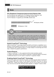
MS-7551 Mainboard Slots PCI (Peripheral Component Interconnect) Express Slot The PCI Express slot supports the PCI Express interface expansion card. PCI Express x 1 Slot PCI Express ...
MS-7551 Mainboard Slots PCI (Peripheral Component Interconnect) Express Slot The PCI Express slot supports the PCI Express interface expansion card. PCI Express x 1 Slot PCI Express ...

User Guide
Page 33
... can send interrupt signals to the PCI bus pins as jumpers, switches or BIOS configuration. The PCI IRQ pins are typically connected to the microprocessor. MS-7551 Mainboard PCI (Peripheral Component Interconnect) Slot The PCI slot supports LAN card, SCSI card, USB card, and other add-on cards that you unplug...
... can send interrupt signals to the PCI bus pins as jumpers, switches or BIOS configuration. The PCI IRQ pins are typically connected to the microprocessor. MS-7551 Mainboard PCI (Peripheral Component Interconnect) Slot The PCI slot supports LAN card, SCSI card, USB card, and other add-on cards that you unplug...

User Guide
Page 34
... refers to the model number. 6th refers to the Chipset vender as A = AMD, I = Intel, V = VIA, N = Nvidia, U = ULi. 7th - 8th digit refers to the customer as MS = all standard customers. English BIOS Setup This chapter provides basic information on the BIOS Setup program and allows you to run the Setup program when...
... refers to the model number. 6th refers to the Chipset vender as A = AMD, I = Intel, V = VIA, N = Nvidia, U = ULi. 7th - 8th digit refers to the customer as MS = all standard customers. English BIOS Setup This chapter provides basic information on the BIOS Setup program and allows you to run the Setup program when...

User Guide
Page 35
... containing additional options can call up this field. Then you can use control keys ( ) to highlight the field and press to field within a sub-menu. MS-7551 Mainboard Entering Setup Power on -line description of the highlighted setup function is the Main Menu. Main Menu The main menu lists the setup...
... containing additional options can call up this field. Then you can use control keys ( ) to highlight the field and press to field within a sub-menu. MS-7551 Mainboard Entering Setup Power on -line description of the highlighted setup function is the Main Menu. Main Menu The main menu lists the setup...

User Guide
Page 37
...for optimal system performance. 2. Adjust the Date, Time fields. 3. If you need the detailed settings of BIOS, please see the manual in English version on MSI website. Important The configuration above are for general use . 1. Save & Exit Setup : Use control keys ( ) to highlight the Save & Exit Setup ...field and press , a message as below appears: Select [Ok] and press Enter to load the default settings for general use only. MS-7551 Mainboard W hen enter the BIOS Setup utility, follow the processes below appears: Select [Ok] and press Enter to save the configurations and...
...for optimal system performance. 2. Adjust the Date, Time fields. 3. If you need the detailed settings of BIOS, please see the manual in English version on MSI website. Important The configuration above are for general use . 1. Save & Exit Setup : Use control keys ( ) to highlight the Save & Exit Setup ...field and press , a message as below appears: Select [Ok] and press Enter to load the default settings for general use only. MS-7551 Mainboard W hen enter the BIOS Setup utility, follow the processes below appears: Select [Ok] and press Enter to save the configurations and...

User Guide
Page 39
... CPU frequency (FSB x Ratio). Advance DRAM Configuration Press to run at 1T (T=clock cycles) rate. Selecting [2T] makes SDRAM signal controller run at 2T rate. MS-7551 Mainboard Important To ensure that : 1. DRAM Timing Mode Setting to [Auto] enables DRAM CAS# Latency automatically to double confirm that Cool'n'Quiet function is...
... CPU frequency (FSB x Ratio). Advance DRAM Configuration Press to run at 1T (T=clock cycles) rate. Selecting [2T] makes SDRAM signal controller run at 2T rate. MS-7551 Mainboard Important To ensure that : 1. DRAM Timing Mode Setting to [Auto] enables DRAM CAS# Latency automatically to double confirm that Cool'n'Quiet function is...

User Guide
Page 41
The Driver menu shows the available drivers. The Driver/Utility CD contains the: Driver menu - Utility menu - Important Please visit the MSI website to activate the device. En-32 Install the driver by your desire and to get the latest drivers and BIOS for better system... performance. The W ebSite menu shows the necessary websites. MS-7551 Mainboard Software Information Take out the Driver/Utility CD that the mainboard supports. W ebSite menu- The installation will auto-run, simply click the...
The Driver menu shows the available drivers. The Driver/Utility CD contains the: Driver menu - Utility menu - Important Please visit the MSI website to activate the device. En-32 Install the driver by your desire and to get the latest drivers and BIOS for better system... performance. The W ebSite menu shows the necessary websites. MS-7551 Mainboard Software Information Take out the Driver/Utility CD that the mainboard supports. W ebSite menu- The installation will auto-run, simply click the...


