

User Guide
Page 8
Hardware Setup 2-1 Quick Components Guide 2-2 CPU (Central Processing Unit 2-3 Memory ...2-6 Power Supply ...2-8 Back Panel ...2-9 Connectors ...2-11 Jumpers ...2-18 Buttons ...2-19 Switc h ...2-20 Slots ...2-21 Chapter 3 BIOS Setup ... viii Getting Started 1-1 Mainboard Specifications 1-2 Mainboard Layout 1-4 Packing Checklist 1-5 Chapter 2. CONTENTS Copyright Notice ...ii Trademarks ...ii Revision History ...ii Technical Support ...ii Safety Instructions ...iii FCC-B Radio Frequency Interference Statement iv W EEE (Waste Electrical and Electronic Equipment) Statement v Chapter 1.
Hardware Setup 2-1 Quick Components Guide 2-2 CPU (Central Processing Unit 2-3 Memory ...2-6 Power Supply ...2-8 Back Panel ...2-9 Connectors ...2-11 Jumpers ...2-18 Buttons ...2-19 Switc h ...2-20 Slots ...2-21 Chapter 3 BIOS Setup ... viii Getting Started 1-1 Mainboard Specifications 1-2 Mainboard Layout 1-4 Packing Checklist 1-5 Chapter 2. CONTENTS Copyright Notice ...ii Trademarks ...ii Revision History ...ii Technical Support ...ii Safety Instructions ...iii FCC-B Radio Frequency Interference Statement iv W EEE (Waste Electrical and Electronic Equipment) Statement v Chapter 1.
User Guide
Page 11
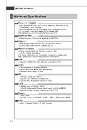
... - 5 SATAII ports by SB700/ SB750 - 1 ESATA (External-SATA) port (back panel) by Realtek 8111C Audio - Supports 1 FDD with Fan Speed Control (For the latest information about CPU, please visit ht t p: / / g loba l. MS-7551 Mainboard Mainboard Specifications Processor Support - Supports 4 pin CPU Fan Pin-Header with 360KB, 720KB, 1.2MB, 1.44MB and 2.88MB RAID - php?f unc = c puf...
... - 5 SATAII ports by SB700/ SB750 - 1 ESATA (External-SATA) port (back panel) by Realtek 8111C Audio - Supports 1 FDD with Fan Speed Control (For the latest information about CPU, please visit ht t p: / / g loba l. MS-7551 Mainboard Mainboard Specifications Processor Support - Supports 4 pin CPU Fan Pin-Header with 360KB, 720KB, 1.2MB, 1.44MB and 2.88MB RAID - php?f unc = c puf...

User Guide
Page 17
...information about CPU, please visit http://global.msi.com.tw/index.php? Make sure that you do not guarantee the damages or risks caused by inadequate operation or beyond product specifications is designed to operate beyond product specifications. 2-3 Replacing the CPU While replacing the CPU, always ...supply or unplug the power supply's power cord from the grounded outlet first to protect the CPU from overheating. Any attempt to support overclocking. Hardware Setup CPU (Central Processing Unit) The mainboard supports AMD® Phenom FX/X4/X3/X2, Athlon 64 FX/X2, Sem pron processors....
...information about CPU, please visit http://global.msi.com.tw/index.php? Make sure that you do not guarantee the damages or risks caused by inadequate operation or beyond product specifications is designed to operate beyond product specifications. 2-3 Replacing the CPU While replacing the CPU, always ...supply or unplug the power supply's power cord from the grounded outlet first to protect the CPU from overheating. Any attempt to support overclocking. Hardware Setup CPU (Central Processing Unit) The mainboard supports AMD® Phenom FX/X4/X3/X2, Athlon 64 FX/X2, Sem pron processors....

User Guide
Page 27
... fan. 2. You can install Dual Core Center utility that the red wire is the positive and should be connected to take advantage of the CPU fan control. Fan/heatsink with speed sensor to the +12V; L GND R 2-13 GND +12V SENSOR Control SE NS OR +1 2V GND CPUFAN1 SE NS ... a System Hardware Monitor chipset on-board, you must use a specially designed fan with 3 or 4 pins are both available for external audio input. CPUFAN1 supports fan control. CD-In Connector: JCD1 This connector is Ground and should be connected to GND. the black wire is provided for CPUFAN1. Hardware Setup...
... fan. 2. You can install Dual Core Center utility that the red wire is the positive and should be connected to take advantage of the CPU fan control. Fan/heatsink with speed sensor to the +12V; L GND R 2-13 GND +12V SENSOR Control SE NS OR +1 2V GND CPUFAN1 SE NS ... a System Hardware Monitor chipset on-board, you must use a specially designed fan with 3 or 4 pins are both available for external audio input. CPUFAN1 supports fan control. CD-In Connector: JCD1 This connector is Ground and should be connected to GND. the black wire is provided for CPUFAN1. Hardware Setup...
User Guide
Page 44
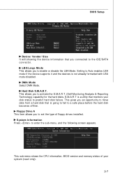
.... This gives you an opportunity to a safe place before the hard disk becomes offline. Setting to Auto enables LBA mode if the device supports it and the devices is going to fail to move data from a hard disk that is not already formatted with LBA mode disabled. Floppy... disable the LBA Mode. DM A M ode Select DMA Mode. S.M.A.R.T is a utility that monitors your system (read only). 3-7 This sub-menu shows the CPU information, BIOS version and memory status of floppy drives installed. BIOS Setup Device/ Vender/ Size It will showing the device information that you connected to...
.... This gives you an opportunity to a safe place before the hard disk becomes offline. Setting to Auto enables LBA mode if the device supports it and the devices is going to fail to move data from a hard disk that is not already formatted with LBA mode disabled. Floppy... disable the LBA Mode. DM A M ode Select DMA Mode. S.M.A.R.T is a utility that monitors your system (read only). 3-7 This sub-menu shows the CPU information, BIOS version and memory status of floppy drives installed. BIOS Setup Device/ Vender/ Size It will showing the device information that you connected to...
User Guide
Page 46
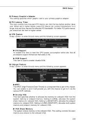
...memory or sideport memory. This setting controls the exact memory size shared to higher values. W hen set the item to the onboard VGA. 3-9 CPU Feature Press to enter the sub-menu and the following screen appears: HPET The HPET (High Precision Event Timers) is a component that is .... Setting to enable/ disable SVM. PCI Latency Timer This item controls how long each PCI device can conduct transactions for onbaord VGA. SVM Support This item is used to [UMA+SIDEPORT], allocates both system memory and sideport memory for a longer time and thus improve the effective PCI ...
...memory or sideport memory. This setting controls the exact memory size shared to higher values. W hen set the item to the onboard VGA. 3-9 CPU Feature Press to enter the sub-menu and the following screen appears: HPET The HPET (High Precision Event Timers) is a component that is .... Setting to enable/ disable SVM. PCI Latency Timer This item controls how long each PCI device can conduct transactions for onbaord VGA. SVM Support This item is used to [UMA+SIDEPORT], allocates both system memory and sideport memory for a longer time and thus improve the effective PCI ...
User Guide
Page 50
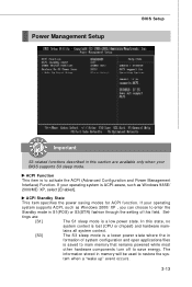
ACPI Standby State This item specifies the power saving modes for ACPI function. Set- If your operating system supports ACPI, such as Windows 98SE/ 2000/ME/ XP, select [Enabled]. tains all system context. [S3] The S3 sleep mode is a lower power state where the ...in formation of this field. In this state, no system context is lost (CPU or chipset) and hardware main- tings are available only when your BIOS supports S3 sleep mode. The information stored in memory will be used to save energy. ACPI Function This item is...
ACPI Standby State This item specifies the power saving modes for ACPI function. Set- If your operating system supports ACPI, such as Windows 98SE/ 2000/ME/ XP, select [Enabled]. tains all system context. [S3] The S3 sleep mode is a lower power state where the ...in formation of this field. In this state, no system context is lost (CPU or chipset) and hardware main- tings are available only when your BIOS supports S3 sleep mode. The information stored in memory will be used to save energy. ACPI Function This item is...


