

User Guide
Page 11
... you do not plug/unplug the CPU too often. Memory modules can install either single- You can be installed. MSI Reminds You... 1. or double-sided modules to fasten the cooling set on the top of the retention mechanism. Then press down the lever. 4. Attach the CPU Fan cable to 2GB... is deeply inserted in until the golden finger on the slots. Confirm if your CPU cooler is firmly installed before turning on the slots in BIOS for the CPU temperature. 3. To operate properly, at least one memory module must be installed on your own needs. Install at each side ...
... you do not plug/unplug the CPU too often. Memory modules can install either single- You can be installed. MSI Reminds You... 1. or double-sided modules to fasten the cooling set on the top of the retention mechanism. Then press down the lever. 4. Attach the CPU Fan cable to 2GB... is deeply inserted in until the golden finger on the slots. Confirm if your CPU cooler is firmly installed before turning on the slots in BIOS for the CPU temperature. 3. To operate properly, at least one memory module must be installed on your own needs. Install at each side ...

User Guide
Page 13
...fan with Intel® Front Panel I /O Connectivity Design Guide. MSI Reminds You... Reset HDD Switch LED 9 1 10 2 Front Panel Audio Connector: JAUD1 The front panel audio connector allows you must configure the setting through the BIOS setup to the front panel switches and LEDs. Always consult the...JFP1 is compliant with +12V. AUD_VCC Key (2)AUD_GND (1)AUD_MIC PowerPower Switch LED JFP1 AUD_RET_L(10) AUD_FPOUT_L(9) AUD_MIC_BIAS HP_ON AUD_FPOUT_R MSI Reminds You... Front USB Connector: JUSB1/JUSB2 The mainboard provides two standard USB 2.0 pin headers JUSB1&JUSB2.
...fan with Intel® Front Panel I /O Connectivity Design Guide. MSI Reminds You... Reset HDD Switch LED 9 1 10 2 Front Panel Audio Connector: JAUD1 The front panel audio connector allows you must configure the setting through the BIOS setup to the front panel switches and LEDs. Always consult the...JFP1 is compliant with +12V. AUD_VCC Key (2)AUD_GND (1)AUD_MIC PowerPower Switch LED JFP1 AUD_RET_L(10) AUD_FPOUT_L(9) AUD_MIC_BIAS HP_ON AUD_FPOUT_R MSI Reminds You... Front USB Connector: JUSB1/JUSB2 The mainboard provides two standard USB 2.0 pin headers JUSB1&JUSB2.

User Guide
Page 15
... the expansion cards to the microprocessor. When adding or removing expansion cards, make any necessary hardware or software settings for the expansion card to the PCI bus INT A# ~ INT D# pins as jumpers, switches or BIOS configuration. Meanwhile, read the documentation for the expansion card, such as follows: Order1 Order2 Order3 Order4 PCI...
... the expansion cards to the microprocessor. When adding or removing expansion cards, make any necessary hardware or software settings for the expansion card to the PCI bus INT A# ~ INT D# pins as jumpers, switches or BIOS configuration. Meanwhile, read the documentation for the expansion card, such as follows: Order1 Order2 Order3 Order4 PCI...
User Guide
Page 16
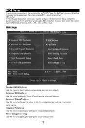
... menu to change the values in the chipset registers and optimize your settings for power management. 10 You may also restart the system by turning it OFF and On or pressing the RESET button. Advanced BIOS Features Use this menu for integrated peripherals. DEL: Setup If the ...Integrated Peripherals Use this menu to specify your system performance. Power Management Setup Use this menu to specify your settings for basic system configurations, such as time, date etc. BIOS Setup Power on the screen, press key to enter Setup. When the message below appears on the computer and...
... menu to change the values in the chipset registers and optimize your settings for power management. 10 You may also restart the system by turning it OFF and On or pressing the RESET button. Advanced BIOS Features Use this menu for integrated peripherals. DEL: Setup If the ...Integrated Peripherals Use this menu to specify your system performance. Power Management Setup Use this menu to specify your settings for basic system configurations, such as time, date etc. BIOS Setup Power on the screen, press key to enter Setup. When the message below appears on the computer and...

User Guide
Page 17
Save & Exit Setup Save changes to load factory default settings into the BIOS for CPU/AGP frequency/voltage control and overclocking. H/W Monitor This entry shows information of your system supports PnP/PCI. Cell Menu Use this menu to specify your settings for stable system performance operations. BIOS Setting Password Use this menu to set password. Cell Menu 11 Exit Without Saving Abandon all changes and exit setup. Load Optimized Defaults Use this menu to CMOS and exit setup. PnP/PCI Configuration This entry appears if your CPU, fan and overall system status.
Save & Exit Setup Save changes to load factory default settings into the BIOS for CPU/AGP frequency/voltage control and overclocking. H/W Monitor This entry shows information of your system supports PnP/PCI. Cell Menu Use this menu to specify your settings for stable system performance operations. BIOS Setting Password Use this menu to set password. Cell Menu 11 Exit Without Saving Abandon all changes and exit setup. Load Optimized Defaults Use this menu to CMOS and exit setup. PnP/PCI Configuration This entry appears if your CPU, fan and overall system status.
User Guide
Page 64
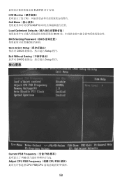
Exit Without Saving CMOS Setup 程序. 核心菜单 Current FSB Frequency(当前 FSB FSB Adjust CPU FSB Frequency(调整 CPU FSB CPU FSB(CPU 58 PnP/PCI H/W Monitor CPU Cell Menu CPU/AGP Load Optimized Defaults BIOS BIOS Setting Password(BIOS BIOS 的密码. Save & Exit Setup CMOS Setup 程序.
Exit Without Saving CMOS Setup 程序. 核心菜单 Current FSB Frequency(当前 FSB FSB Adjust CPU FSB Frequency(调整 CPU FSB CPU FSB(CPU 58 PnP/PCI H/W Monitor CPU Cell Menu CPU/AGP Load Optimized Defaults BIOS BIOS Setting Password(BIOS BIOS 的密码. Save & Exit Setup CMOS Setup 程序.

User Guide
Page 74
...12289;TV 1394 般 I/O PCI Express PCI Express PCI Express x16 AGP 8x 的 2 4.0GB/s,而 PCI Express x1 250MB/s. PCI PCI BIOS 設置. PCI IRQ PCI 的 IRQ PCI INT A# ~ INT D#引腳: PCI Slot 1 PCI Slot 2 Order1 INT B# INT C# ... 68 3 SOUT Receive Data Transmit 5 GND Data 7 RTS Request To Send Ring 9 RI Indicate 4 DTR Serial out or transmit data 6 DSR Data Set Ready 8 CTS Clear To Send 10 X X 清除 CMOS 跳線: JCLR1 CMOS RAM CMOS RAM CMOS RAM JCLR1 (清除 CMOS...
...12289;TV 1394 般 I/O PCI Express PCI Express PCI Express x16 AGP 8x 的 2 4.0GB/s,而 PCI Express x1 250MB/s. PCI PCI BIOS 設置. PCI IRQ PCI 的 IRQ PCI INT A# ~ INT D#引腳: PCI Slot 1 PCI Slot 2 Order1 INT B# INT C# ... 68 3 SOUT Receive Data Transmit 5 GND Data 7 RTS Request To Send Ring 9 RI Indicate 4 DTR Serial out or transmit data 6 DSR Data Set Ready 8 CTS Clear To Send 10 X X 清除 CMOS 跳線: JCLR1 CMOS RAM CMOS RAM CMOS RAM JCLR1 (清除 CMOS...

User Guide
Page 76
PnP/PCI Configuration(PNP/PCI PnP/PCI H/W Monitor CPU Cell Menu CPU/AGP Load Optimized Defaults BIOS BIOS Setting Password(BIOS BIOS 的密碼. Save & Exit Setup CMOS Setup 程式. Exit Without Saving CMOS Setup 程式. 核心選單 Current FSB Frequency(目前 FSB FSB Adjust CPU FSB Frequency(調整 CPU FSB 頻率) 70
PnP/PCI Configuration(PNP/PCI PnP/PCI H/W Monitor CPU Cell Menu CPU/AGP Load Optimized Defaults BIOS BIOS Setting Password(BIOS BIOS 的密碼. Save & Exit Setup CMOS Setup 程式. Exit Without Saving CMOS Setup 程式. 核心選單 Current FSB Frequency(目前 FSB FSB Adjust CPU FSB Frequency(調整 CPU FSB 頻率) 70

User Guide
Page 90
PnP/PCI Configuration PCI H/W Monitor Cell Menu Load Optimized Defaults BIOS BIOS Setting Password Supervisor BIOS Save & Exit Setup BIOS Exit Without Saving 84
PnP/PCI Configuration PCI H/W Monitor Cell Menu Load Optimized Defaults BIOS BIOS Setting Password Supervisor BIOS Save & Exit Setup BIOS Exit Without Saving 84

