
User Guide
Page 9
On-Board LAN l Realtek 8201CL - Supports ACPI Power Management BIOS l Award(LPC) Flash ROM Dimension l Micro-ATX Form Factor: 24.4 cm (L) x 22.4 cm (W) Mounting l 6 mounting holes 3 Audio l AC'97 link controller integrated in one chip. - l 6-channel audio codec Realtek ALC883. - Supports 10Mb/s, 100Mb/s. - Meet PC2001 audio performance requirement. Compliance with AC97 v2.3 Spec. - Compliance with PCI 2.2. - Integrated Fast Ethernet MAC and PHY in VIA 8237A chipset.
On-Board LAN l Realtek 8201CL - Supports ACPI Power Management BIOS l Award(LPC) Flash ROM Dimension l Micro-ATX Form Factor: 24.4 cm (L) x 22.4 cm (W) Mounting l 6 mounting holes 3 Audio l AC'97 link controller integrated in one chip. - l 6-channel audio codec Realtek ALC883. - Supports 10Mb/s, 100Mb/s. - Meet PC2001 audio performance requirement. Compliance with AC97 v2.3 Spec. - Compliance with PCI 2.2. - Integrated Fast Ethernet MAC and PHY in VIA 8237A chipset.
User Guide
Page 11
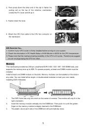
MSI Reminds You... 1. Please note that the mating/unmating durability of the clip to 2GB. You can be installed. Attach the CPU Fan cable to meet ... DDR II Modules Volt Notch 1. The DDR II slot has only one DIMM module must be installed on the memory module is deeply inserted in BIOS for the CPU temperature. 3. The module will automatically close. 5 Memory The mainboard provides two 240-pin unbuffered DDR II 400 / 533 / 667 / 800 DIMM slots...
MSI Reminds You... 1. Please note that the mating/unmating durability of the clip to 2GB. You can be installed. Attach the CPU Fan cable to meet ... DDR II Modules Volt Notch 1. The DDR II slot has only one DIMM module must be installed on the memory module is deeply inserted in BIOS for the CPU temperature. 3. The module will automatically close. 5 Memory The mainboard provides two 240-pin unbuffered DDR II 400 / 533 / 667 / 800 DIMM slots...

User Guide
Page 13
... and LEDs. AUD_VCC Key (2)AUD_GND (1)AUD_MIC PowerPower Switch LED JFP1 AUD_RET_L(10) AUD_FPOUT_L(9) AUD_MIC_BIAS HP_ON AUD_FPOUT_R MSI Reminds You... GND USB0+ USB0C(10) Key(9) 7 IrDA Infrared Module Header: JIR1 The connector allows ...fan) support system cooling fan with speed sensor to the rear audio ports. GND (2)VCC (1)VCC USB0- MSI Reminds You... Front Panel Connectors: JFP1 The mainboard provides two front panel connectors for the proper CPU cooling fan...on -board, you must configure the setting through the BIOS setup to use a specially designed fan with +12V.
... and LEDs. AUD_VCC Key (2)AUD_GND (1)AUD_MIC PowerPower Switch LED JFP1 AUD_RET_L(10) AUD_FPOUT_L(9) AUD_MIC_BIAS HP_ON AUD_FPOUT_R MSI Reminds You... GND USB0+ USB0C(10) Key(9) 7 IrDA Infrared Module Header: JIR1 The connector allows ...fan) support system cooling fan with speed sensor to the rear audio ports. GND (2)VCC (1)VCC USB0- MSI Reminds You... Front Panel Connectors: JFP1 The mainboard provides two front panel connectors for the proper CPU cooling fan...on -board, you must configure the setting through the BIOS setup to use a specially designed fan with +12V.

User Guide
Page 15
.... The PCI IRQ pins are hardware lines over which devices can send interrupt signals to the PCI bus INT A# ~ INT D# pins as jumpers, switches or BIOS configuration. When adding or removing expansion cards, make sure that you to insert the expansion cards to make any necessary hardware or software settings for...
.... The PCI IRQ pins are hardware lines over which devices can send interrupt signals to the PCI bus INT A# ~ INT D# pins as jumpers, switches or BIOS configuration. When adding or removing expansion cards, make sure that you to insert the expansion cards to make any necessary hardware or software settings for...

User Guide
Page 16
Main Page Standard CMOS Features Use this menu for integrated peripherals. Integrated Peripherals Use this menu to setup the items of Award special enhanced features. BIOS Setup Power on the screen, press key to change the values in the chipset registers and optimize your system performance. DEL: Setup If the message ..., such as time, date etc. When the message below appears on the computer and the system will start POST (Power On Self Test) process. Advanced BIOS Features Use this menu to enter Setup.
Main Page Standard CMOS Features Use this menu for integrated peripherals. Integrated Peripherals Use this menu to setup the items of Award special enhanced features. BIOS Setup Power on the screen, press key to change the values in the chipset registers and optimize your system performance. DEL: Setup If the message ..., such as time, date etc. When the message below appears on the computer and the system will start POST (Power On Self Test) process. Advanced BIOS Features Use this menu to enter Setup.
User Guide
Page 17
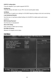
Cell Menu Use this menu to load factory default settings into the BIOS for CPU/AGP frequency/voltage control and overclocking. Load Optimized Defaults Use this menu to CMOS and exit setup. Cell Menu 11 Exit Without Saving Abandon all changes and exit setup. H/W Monitor This entry shows information of your system supports PnP/PCI. Save & Exit Setup Save changes to set password. BIOS Setting Password Use this menu to specify your settings for stable system performance operations. PnP/PCI Configuration This entry appears if your CPU, fan and overall system status.
Cell Menu Use this menu to load factory default settings into the BIOS for CPU/AGP frequency/voltage control and overclocking. Load Optimized Defaults Use this menu to CMOS and exit setup. Cell Menu 11 Exit Without Saving Abandon all changes and exit setup. H/W Monitor This entry shows information of your system supports PnP/PCI. Save & Exit Setup Save changes to set password. BIOS Setting Password Use this menu to specify your settings for stable system performance operations. PnP/PCI Configuration This entry appears if your CPU, fan and overall system status.

User Guide
Page 59
DDR II DIMM 2. 将 DIMM DIMM 3. 2 3 4. 将 CPU CPU 1 CPU 2. 在 BIOS CPU CPU 的温度. 3. 请注意 CPU 20 CPU. 内存 2 条 240-pin DDR II 400 / 533 / 667 / 800 DIMM 2GB 1 条 DIMM 1 条 DIMM Volt Notch 1. DIMM ATX 24-Pin ATX1 ATX ATX 20-pin ATX 20-pin ATX pin 1 和 pin 13 pin 11, 12, 23 和 24 +3.3V -12V GND PS-ON# GND GND GND Res +5V +5V +5V GND 13 1 24 12 +3.3V +3.3V GND +5V GND +5V GND PWR OK 5VSB +12V +12V NC 53
DDR II DIMM 2. 将 DIMM DIMM 3. 2 3 4. 将 CPU CPU 1 CPU 2. 在 BIOS CPU CPU 的温度. 3. 请注意 CPU 20 CPU. 内存 2 条 240-pin DDR II 400 / 533 / 667 / 800 DIMM 2GB 1 条 DIMM 1 条 DIMM Volt Notch 1. DIMM ATX 24-Pin ATX1 ATX ATX 20-pin ATX 20-pin ATX pin 1 和 pin 13 pin 11, 12, 23 和 24 +3.3V -12V GND PS-ON# GND GND GND Res +5V +5V +5V GND 13 1 24 12 +3.3V +3.3V GND +5V GND +5V GND PWR OK 5VSB +12V +12V NC 53

User Guide
Page 64
Exit Without Saving CMOS Setup 程序. 核心菜单 Current FSB Frequency(当前 FSB FSB Adjust CPU FSB Frequency(调整 CPU FSB CPU FSB(CPU 58 Save & Exit Setup CMOS Setup 程序. PnP/PCI H/W Monitor CPU Cell Menu CPU/AGP Load Optimized Defaults BIOS BIOS Setting Password(BIOS BIOS 的密码.
Exit Without Saving CMOS Setup 程序. 核心菜单 Current FSB Frequency(当前 FSB FSB Adjust CPU FSB Frequency(调整 CPU FSB CPU FSB(CPU 58 Save & Exit Setup CMOS Setup 程序. PnP/PCI H/W Monitor CPU Cell Menu CPU/AGP Load Optimized Defaults BIOS BIOS Setting Password(BIOS BIOS 的密码.

User Guide
Page 70
...-pin ATX pin 1 和 pin 13 pin 11, 12, 23 和 24 ATX 12V JPW1 此 12V CPU 供電. 3 4. 將 CPU CPU 1 CPU 2. 在 BIOS CPU CPU 的溫度. 3. 請注意 CPU 20 CPU. 記憶體 2 條 240-pin DDR II 400 / 533 / 667 / 800 DIMM 2GB...
...-pin ATX pin 1 和 pin 13 pin 11, 12, 23 和 24 ATX 12V JPW1 此 12V CPU 供電. 3 4. 將 CPU CPU 1 CPU 2. 在 BIOS CPU CPU 的溫度. 3. 請注意 CPU 20 CPU. 記憶體 2 條 240-pin DDR II 400 / 533 / 667 / 800 DIMM 2GB...

User Guide
Page 75
Save & Exit Setup CMOS Setup 程式. PnP/PCI Configuration(PNP/PCI PnP/PCI H/W Monitor CPU Cell Menu CPU/AGP Load Optimized Defaults BIOS BIOS Setting Password(BIOS BIOS 的密碼. Exit Without Saving CMOS Setup 程式. 核心選單 Current FSB Frequency(目前 FSB FSB Adjust CPU FSB Frequency(調整 CPU FSB CPU FSB(CPU 69
Save & Exit Setup CMOS Setup 程式. PnP/PCI Configuration(PNP/PCI PnP/PCI H/W Monitor CPU Cell Menu CPU/AGP Load Optimized Defaults BIOS BIOS Setting Password(BIOS BIOS 的密碼. Exit Without Saving CMOS Setup 程式. 核心選單 Current FSB Frequency(目前 FSB FSB Adjust CPU FSB Frequency(調整 CPU FSB CPU FSB(CPU 69

User Guide
Page 84
... 12V の 4 CPU_FAN (processor fan 3 SYS_FAN (system fan 2 GND 1 CINTRU Control SENSOR +12V GND CPU_FAN GND +12V NC SYS_FAN ります。 . IrDA JIR1 BIOS の中の IR JIR1 は Intel Front Panel I /O Connectivity Design Guide (2)AUD_GND (1)AUD_MIC AUD_MIC_BIAS HP_ON AUD_FPOUT_R AUD_RET_L(10) AUD_FPOUT_L(9) 5、6 と 9、10 78
... 12V の 4 CPU_FAN (processor fan 3 SYS_FAN (system fan 2 GND 1 CINTRU Control SENSOR +12V GND CPU_FAN GND +12V NC SYS_FAN ります。 . IrDA JIR1 BIOS の中の IR JIR1 は Intel Front Panel I /O Connectivity Design Guide (2)AUD_GND (1)AUD_MIC AUD_MIC_BIAS HP_ON AUD_FPOUT_R AUD_RET_L(10) AUD_FPOUT_L(9) 5、6 と 9、10 78

User Guide
Page 87
BIOS Setup POST(Power On Self Test DEL DEL: Setup F11: Boot Menu TAB: Logo 、、を Main Page Standard CMOS Features Advanced BIOS Features Advanced Chipset Features Integrated Peripherals IDE Power Management Setup 81
BIOS Setup POST(Power On Self Test DEL DEL: Setup F11: Boot Menu TAB: Logo 、、を Main Page Standard CMOS Features Advanced BIOS Features Advanced Chipset Features Integrated Peripherals IDE Power Management Setup 81

User Guide
Page 88
PnP/PCI Configuration PCI H/W Monitor Cell Menu Load Optimized Defaults BIOS BIOS Setting Password Supervisor BIOS Save & Exit Setup BIOS Exit Without Saving 82
PnP/PCI Configuration PCI H/W Monitor Cell Menu Load Optimized Defaults BIOS BIOS Setting Password Supervisor BIOS Save & Exit Setup BIOS Exit Without Saving 82
