
User Guide
Page 4
... on a circuit different from that to which the receiver is no guarantee that may cause undesired operation. Notice 2 Shielded interface cables and A.C. Micro-Star International MS-7508 This device complies with the instructions, may not cause harmful interference, and (2) this device may cause harmful interference to radio communications. iv VOIR LANOTICE D'INSTALLATIONAVANT...
... on a circuit different from that to which the receiver is no guarantee that may cause undesired operation. Notice 2 Shielded interface cables and A.C. Micro-Star International MS-7508 This device complies with the instructions, may not cause harmful interference, and (2) this device may cause harmful interference to radio communications. iv VOIR LANOTICE D'INSTALLATIONAVANT...
User Guide
Page 11
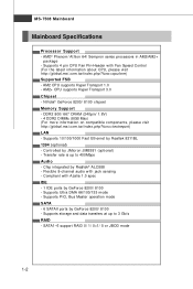
... JMicron JMB381 (optional) - Supports storage and data transfers at up to 3 Gb/s RAID - NVidia® GeForce 8200/ 8100 chipset Memory Support - ms i. Supports Ultra DMA 66/100/133 mode - MS-7508 Mainboard Mainboard Specifications Processor Support - AM2 CPU supports Hyper Transport 1.0 - Supports 10/100/1000 Fast Ethernet by GeForce 8200/ 8100 - Flexible 8-channel...
... JMicron JMB381 (optional) - Supports storage and data transfers at up to 3 Gb/s RAID - NVidia® GeForce 8200/ 8100 chipset Memory Support - ms i. Supports Ultra DMA 66/100/133 mode - MS-7508 Mainboard Mainboard Specifications Processor Support - AM2 CPU supports Hyper Transport 1.0 - Supports 10/100/1000 Fast Ethernet by GeForce 8200/ 8100 - Flexible 8-channel...
User Guide
Page 13
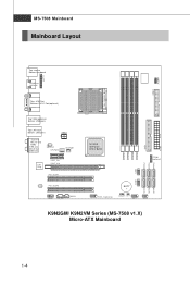
MS-7508 Mainboard Mainboard Layout JC OM1 JLPT1 Top : mouse Bottom: keyboard HDMI Port (optional) FDD 1 Top : VGA Port Bottom: DVI-D Port(optional) Top:1394 (optional) Bottom: .../ 8200 DIMM1 DIMM2 DIMM3 DIMM4 JTPM1 (o pt ional ) SATA2 SATA3 SATA5 JUSB2 JUSB1 SATA1 SATA4 SATA6 J13 94_1(opt ional) BAT T + JVBAT1 J CI1 JFP1 JFP2 K9N2GM/ K9N2VM Series (MS-7508 v1.X) Micro-ATX Mainboard IDE1 ATX1 1-4 Out B:Mic T: RS -Out M :CS-
MS-7508 Mainboard Mainboard Layout JC OM1 JLPT1 Top : mouse Bottom: keyboard HDMI Port (optional) FDD 1 Top : VGA Port Bottom: DVI-D Port(optional) Top:1394 (optional) Bottom: .../ 8200 DIMM1 DIMM2 DIMM3 DIMM4 JTPM1 (o pt ional ) SATA2 SATA3 SATA5 JUSB2 JUSB1 SATA1 SATA4 SATA6 J13 94_1(opt ional) BAT T + JVBAT1 J CI1 JFP1 JFP2 K9N2GM/ K9N2VM Series (MS-7508 v1.X) Micro-ATX Mainboard IDE1 ATX1 1-4 Out B:Mic T: RS -Out M :CS-
User Guide
Page 18
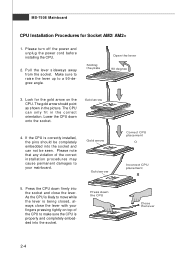
... lever with your mainboard. Gold arrow Gold arrow Correct CPU placement O Incorrect CPU placement 5. Look for Socket AM2/ AM2+ 1. The CPU can not be seen. MS-7508 Mainboard CPU Installation Procedures for the gold arrow on top of the correct installation procedures may cause permanent damages to a 90-degree angle.
... lever with your mainboard. Gold arrow Gold arrow Correct CPU placement O Incorrect CPU placement 5. Look for Socket AM2/ AM2+ 1. The CPU can not be seen. MS-7508 Mainboard CPU Installation Procedures for the gold arrow on top of the correct installation procedures may cause permanent damages to a 90-degree angle.
User Guide
Page 20
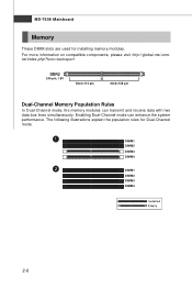
...-pin, 1.8V 56x2=112 pin 64x2=128 pin Dual-Channel Memory Population Rules In Dual-Channel mode, the memory modules can enhance the system performance. MS-7508 Mainboard Memory These DIMM slots are used for Dual-Channel mode. 1 DIMM1 DIMM2 DIMM3 DIMM4 2 DIMM1 DIMM2 DIMM3 DIMM4 Installed Empty 2-6 For more information on...
...-pin, 1.8V 56x2=112 pin 64x2=128 pin Dual-Channel Memory Population Rules In Dual-Channel mode, the memory modules can enhance the system performance. MS-7508 Mainboard Memory These DIMM slots are used for Dual-Channel mode. 1 DIMM1 DIMM2 DIMM3 DIMM4 2 DIMM1 DIMM2 DIMM3 DIMM4 Installed Empty 2-6 For more information on...
User Guide
Page 22
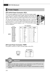
... to proper ATX power supplies to ensure stable operation of the power supply is used to provide power to avoid wrong installation. If you'd like . MS-7508 Mainboard Power Supply ATX 24-Pin Power Connector: ATX1 This connector allows you like to use the 20-pin ATX power supply as you to...
... to proper ATX power supplies to ensure stable operation of the power supply is used to provide power to avoid wrong installation. If you'd like . MS-7508 Mainboard Power Supply ATX 24-Pin Power Connector: ATX1 This connector allows you like to use the 20-pin ATX power supply as you to...
User Guide
Page 24
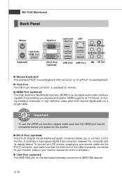
... end of transmitting uncompressed streams. HDMI supports all TV format, including standard, enhanced, or high-definition video, plus multi-channel digital audio on a single cable. MS-7508 Mainboard Back Panel Mouse (optional) HDMI Port Keyboard VGA Port (optional) LAN 1394 Port Line-In RS-Out Line-Out CS-Out DVI-D Port (optional...
... end of transmitting uncompressed streams. HDMI supports all TV format, including standard, enhanced, or high-definition video, plus multi-channel digital audio on a single cable. MS-7508 Mainboard Back Panel Mouse (optional) HDMI Port Keyboard VGA Port (optional) LAN 1394 Port Line-In RS-Out Line-Out CS-Out DVI-D Port (optional...
User Guide
Page 26
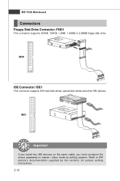
MS-7508 Mainboard Connectors Floppy Disk Drive Connector: FDD1 This connector supports 360KB, 720KB, 1.2MB, 1.44MB or 2.88MB floppy disk drive. IDE1 Important If you install two IDE devices on the same cable, you must configure the drives separately to IDE device's documentation supplied by setting jumpers. FDD1 IDE Connector: IDE1 This connector supports IDE hard disk drives, optical disk drives and other IDE devices. Refer to master / slave mode by the vendors for jumper setting instructions. 2-12
MS-7508 Mainboard Connectors Floppy Disk Drive Connector: FDD1 This connector supports 360KB, 720KB, 1.2MB, 1.44MB or 2.88MB floppy disk drive. IDE1 Important If you install two IDE devices on the same cable, you must configure the drives separately to IDE device's documentation supplied by setting jumpers. FDD1 IDE Connector: IDE1 This connector supports IDE hard disk drives, optical disk drives and other IDE devices. Refer to master / slave mode by the vendors for jumper setting instructions. 2-12
User Guide
Page 28
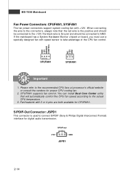
... connecting the wire to the connectors, always note that will automatically control the CPU fan speed according to take advantage of the CPU fan control. MS-7508 Mainboard Fan Power Connectors: CPUFAN1, SYSFAN1 The fan power connectors support system cooling fan with speed sensor to the actual CPU temperature. 3. the black wire...
... connecting the wire to the connectors, always note that will automatically control the CPU fan speed according to take advantage of the CPU fan control. MS-7508 Mainboard Fan Power Connectors: CPUFAN1, SYSFAN1 The fan power connectors support system cooling fan with speed sensor to the actual CPU temperature. 3. the black wire...
User Guide
Page 30
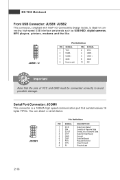
MS-7508 Mainboard Front USB Connector: JUSB1/ JUSB2 This connector, compliant with Intel® I/O Connectivity Design Guide, is a 16550A high speed communication port that the pins of ...
MS-7508 Mainboard Front USB Connector: JUSB1/ JUSB2 This connector, compliant with Intel® I/O Connectivity Design Guide, is a 16550A high speed communication port that the pins of ...
User Guide
Page 32
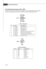
MS-7508 Mainboard Front Panel Connectors: JFP1, JFP2 These connectors are for electrical connection to GND Reserved. The JFP1 is compliant with Intel® Front Panel I/O Connectivity ...
MS-7508 Mainboard Front Panel Connectors: JFP1, JFP2 These connectors are for electrical connection to GND Reserved. The JFP1 is compliant with Intel® Front Panel I/O Connectivity ...
User Guide
Page 34
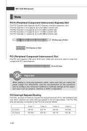
... that comply with PCI specifications. 32-bit PCI Slot Important When adding or removing expansion cards, make sure that you unplug the power supply first. MS-7508 Mainboard Slots PCI-E (Peripheral Component Interconnect-Express) Slot The PCI Express slot supports the PCI Express interface expansion card.
... that comply with PCI specifications. 32-bit PCI Slot Important When adding or removing expansion cards, make sure that you unplug the power supply first. MS-7508 Mainboard Slots PCI-E (Peripheral Component Interconnect-Express) Slot The PCI Express slot supports the PCI Express interface expansion card.
User Guide
Page 36
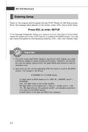
... to the model number. 6th digit refers to the chipset as I = Intel, N = nVidia, and V = VIA. 7th - 8th digit refers to the customer as MS = all standard customers. MS-7508 Mainboard Entering Setup Power on the screen, press key to enter Setup. Upon boot-up, the 1st line appearing after the memory count is...
... to the model number. 6th digit refers to the chipset as I = Intel, N = nVidia, and V = VIA. 7th - 8th digit refers to the customer as MS = all standard customers. MS-7508 Mainboard Entering Setup Power on the screen, press key to enter Setup. Upon boot-up, the 1st line appearing after the memory count is...
User Guide
Page 38
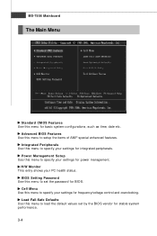
... for basic system configurations, such as time, date etc. BIOS Setting Password Use this menu to setup the items of AMI® special enhanced features. MS-7508 Mainboard The Main Menu Standard CMOS Features Use this menu to specify your settings for power management. H/W Monitor This entry shows your PC health status...
... for basic system configurations, such as time, date etc. BIOS Setting Password Use this menu to setup the items of AMI® special enhanced features. MS-7508 Mainboard The Main Menu Standard CMOS Features Use this menu to specify your settings for power management. H/W Monitor This entry shows your PC health status...
User Guide
Page 40
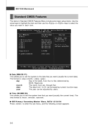
... format is . Read-only. Time (HH:MM :SS) This allows you to set the system to select the value you want (usually the current time). MS-7508 Mainboard Standard CMOS Features The items in each item. The format is . month The month from 1 to enter the sub-menu, and the following screen...
... format is . Read-only. Time (HH:MM :SS) This allows you to set the system to select the value you want (usually the current time). MS-7508 Mainboard Standard CMOS Features The items in each item. The format is . month The month from 1 to enter the sub-menu, and the following screen...
User Guide
Page 42
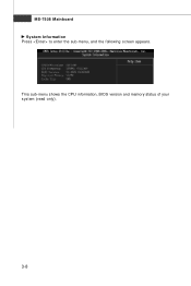
MS-7508 Mainboard System Information Press to enter the sub-menu, and the following screen appears. This sub-menu shows the CPU information, BIOS version and memory status of your system (read only). 3-8
MS-7508 Mainboard System Information Press to enter the sub-menu, and the following screen appears. This sub-menu shows the CPU information, BIOS version and memory status of your system (read only). 3-8
User Guide
Page 44
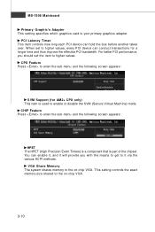
... provide you should set to higher values, every PCI device can hold the bus before another takes over. W hen set the item to higher values. MS-7508 Mainboard Primary Graphic's Adapter This setting specifies which graphics card is used to enable or disable the SVM (Secure Virtual Machine) mode. CHIP Feature Press...
... provide you should set to higher values, every PCI device can hold the bus before another takes over. W hen set the item to higher values. MS-7508 Mainboard Primary Graphic's Adapter This setting specifies which graphics card is used to enable or disable the SVM (Secure Virtual Machine) mode. CHIP Feature Press...
User Guide
Page 46
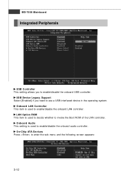
... invoke the Boot ROM of the LAN controller. LAN Option ROM This item is used to decide whether to enable/disable the onboard LAN controller. MS-7508 Mainboard Integrated Peripherals USB Controller This setting allows you need to use a USB-interfaced device in the operating system.
... invoke the Boot ROM of the LAN controller. LAN Option ROM This item is used to decide whether to enable/disable the onboard LAN controller. MS-7508 Mainboard Integrated Peripherals USB Controller This setting allows you need to use a USB-interfaced device in the operating system.
User Guide
Page 48
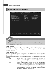
... through the setting of this field. The information stored in memory will be used to activate the ACPI (Advanced Configuration and Power Management Interface) Function. MS-7508 Mainboard Power Management Setup Important S3-related functions described in this section are : [S1] The S1 sleep mode is a low power state. ACPI Function This...
... through the setting of this field. The information stored in memory will be used to activate the ACPI (Advanced Configuration and Power Management Interface) Function. MS-7508 Mainboard Power Management Setup Important S3-related functions described in this section are : [S1] The S1 sleep mode is a low power state. ACPI Function This...
User Guide
Page 50
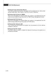
MS-7508 Mainboard Resume From S3 By PS/2 M ouse This setting determines whether the system will be powered on by the devices installed in LAN port. Resume ...
MS-7508 Mainboard Resume From S3 By PS/2 M ouse This setting determines whether the system will be powered on by the devices installed in LAN port. Resume ...


