
User Guide
Page 8
... Statement iv W EEE (Waste Electrical and Electronic Equipment) Statement v Chapter 1. Hardware Setup 2-1 Quick Components Guide 2-2 CPU (Central Processing Unit 2-3 Memory ...2-6 Power Supply ...2-8 Back Panel ...2-10 Connectors ...2-12 Slots ...2-20 Chapter 3 BIOS Setup 3-1 Entering Setup ...3-2 The Main Menu... ...3-4 Standard CMOS Features 3-6 Advanced BIOS Features 3-9 Integrated Peripherals 3-12 Power Management Setup 3-14 H/W Monitor ...3-17 Cell Menu ...3-18 Load Fail-Safe/ Optimized Defaults 3-23 BIOS Setting Password 3-24 ...
... Statement iv W EEE (Waste Electrical and Electronic Equipment) Statement v Chapter 1. Hardware Setup 2-1 Quick Components Guide 2-2 CPU (Central Processing Unit 2-3 Memory ...2-6 Power Supply ...2-8 Back Panel ...2-10 Connectors ...2-12 Slots ...2-20 Chapter 3 BIOS Setup 3-1 Entering Setup ...3-2 The Main Menu... ...3-4 Standard CMOS Features 3-6 Advanced BIOS Features 3-9 Integrated Peripherals 3-12 Power Management Setup 3-14 H/W Monitor ...3-17 Cell Menu ...3-18 Load Fail-Safe/ Optimized Defaults 3-23 BIOS Setting Password 3-24 ...
User Guide
Page 17
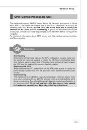
...Important Overheating Overheating will seriously damage the CPU and system. W hen you apply an even layer of CPU. For the latest information about CPU, please visit http://global.msi.com.tw/index. The Socket AM2/ AM2+ offer a easy CPU installation. However, please make sure the...product specifications. 2-3 Any attempt to support overclocking. Replacing the CPU While replacing the CPU, always turn off the ATX power supply or unplug the power supply's power cord from the grounded outlet first to protect the CPU from overheating. Always make sure your dealer to enhance heat ...
...Important Overheating Overheating will seriously damage the CPU and system. W hen you apply an even layer of CPU. For the latest information about CPU, please visit http://global.msi.com.tw/index. The Socket AM2/ AM2+ offer a easy CPU installation. However, please make sure the...product specifications. 2-3 Any attempt to support overclocking. Replacing the CPU While replacing the CPU, always turn off the ATX power supply or unplug the power supply's power cord from the grounded outlet first to protect the CPU from overheating. Always make sure your dealer to enhance heat ...
User Guide
Page 18
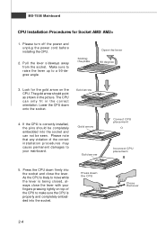
... always close the lever. Press down onto the socket. Sliding the plate Open the lever 90 degree 3. Gold arrow Gold arrow Correct CPU placement O Incorrect CPU placement 5. Look for Socket AM2/ AM2+ 1. The gold arrow should be completely embedded into the socket and close the lever with your...firmly into the socket and can only fit in the picture. Gold arrow 4. The CPU can not be seen. Please turn off the power and unplug the power cord before installing the CPU. 2. If the CPU is properly and completely embedded into the socket. Make sure to raise the lever up...
... always close the lever. Press down onto the socket. Sliding the plate Open the lever 90 degree 3. Gold arrow Gold arrow Correct CPU placement O Incorrect CPU placement 5. Look for Socket AM2/ AM2+ 1. The gold arrow should be completely embedded into the socket and close the lever with your...firmly into the socket and can only fit in the picture. Gold arrow 4. The CPU can not be seen. Please turn off the power and unplug the power cord before installing the CPU. 2. If the CPU is properly and completely embedded into the socket. Make sure to raise the lever up...
User Guide
Page 22
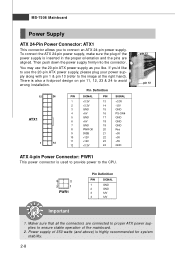
There is used to provide power to the CPU. 4 2 3 1 PWR1 Pin Definition PIN SIGNAL 1 GND 2 GND 3 12V 4 12V pin 13 pin 12 Important 1. Pin Definition 12 24 PIN SIGNAL PIN SIGNAL ATX1 1 13 1 +3.3V ... 19 GND 8 PW R OK 20 Res 9 5VSB 21 +5V 10 +12V 22 +5V 11 +12V 23 +5V 12 +3.3V 24 GND ATX 4-pin Power Connector: PWR1 This power connector is also a foolproof design on pin 11, 12, 23 & 24 to ensure stable operation of 350 watts (and above) is highly recommended for...
There is used to provide power to the CPU. 4 2 3 1 PWR1 Pin Definition PIN SIGNAL 1 GND 2 GND 3 12V 4 12V pin 13 pin 12 Important 1. Pin Definition 12 24 PIN SIGNAL PIN SIGNAL ATX1 1 13 1 +3.3V ... 19 GND 8 PW R OK 20 Res 9 5VSB 21 +5V 10 +12V 22 +5V 11 +12V 23 +5V 12 +3.3V 24 GND ATX 4-pin Power Connector: PWR1 This power connector is also a foolproof design on pin 11, 12, 23 & 24 to ensure stable operation of 350 watts (and above) is highly recommended for...
User Guide
Page 28
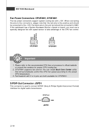
...is the positive and should be connected to the +12V; MS-7508 Mainboard Fan Power Connectors: CPUFAN1, SYSFAN1 The fan power connectors support system cooling fan with speed sensor to take advantage of the CPU fan control. GND +12V SENSOR CONTROL NC +12V GND CPUFAN1 SYSFAN1 Important 1. ...Please refer to the actual CPU temperature. 3. SPDIF-out VCC GND JSPD1 2-14 You can install...
...is the positive and should be connected to the +12V; MS-7508 Mainboard Fan Power Connectors: CPUFAN1, SYSFAN1 The fan power connectors support system cooling fan with speed sensor to take advantage of the CPU fan control. GND +12V SENSOR CONTROL NC +12V GND CPUFAN1 SYSFAN1 Important 1. ...Please refer to the actual CPU temperature. 3. SPDIF-out VCC GND JSPD1 2-14 You can install...
User Guide
Page 48
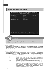
ACPI Function This item is lost (CPU or chipset) and hardware main- Set- ACPI Standby State This item specifies the power saving modes for ACPI function. In this state, no system context is to restore the system when a "wake up" event occurs. 3-14 tings are available ... mode. The information stored in formation of this field. tains all system context. [S3] The S3 sleep mode is saved to main memory that remains powered while most other hardware components turn off to enter the Standby mode in this section are : [S1] The S1 sleep mode is ACPI-aware, such...
ACPI Function This item is lost (CPU or chipset) and hardware main- Set- ACPI Standby State This item specifies the power saving modes for ACPI function. In this state, no system context is to restore the system when a "wake up" event occurs. 3-14 tings are available ... mode. The information stored in formation of this field. tains all system context. [S3] The S3 sleep mode is saved to main memory that remains powered while most other hardware components turn off to enter the Standby mode in this section are : [S1] The S1 sleep mode is ACPI-aware, such...
User Guide
Page 52
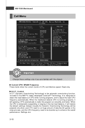
... D.O.T. (Dynamic Overclocking Technology) is designed to detect the load balance of CPU while running programs, it will be powered only when users' PC need to be boosted up to adjust the best CPU frequency automatically. D.O.T. Settings are familiar with the chipset. Current CPU/ DRAM Frequency These items show the current clocks of data like...
... D.O.T. (Dynamic Overclocking Technology) is designed to detect the load balance of CPU while running programs, it will be powered only when users' PC need to be boosted up to adjust the best CPU frequency automatically. D.O.T. Settings are familiar with the chipset. Current CPU/ DRAM Frequency These items show the current clocks of data like...

User Guide
Page 53
... function is activated and will be unstable or reboot incidentally, it's better to disable the Dynamic Overclocking or to double confirm that your CPU can effectively and dynamically lower CPU speed and power consumption. Important Even though the Dynamic Overclocking Technology is more stable than manual overclocking, basically, it is still risky. Enter...
... function is activated and will be unstable or reboot incidentally, it's better to disable the Dynamic Overclocking or to double confirm that your CPU can effectively and dynamically lower CPU speed and power consumption. Important Even though the Dynamic Overclocking Technology is more stable than manual overclocking, basically, it is still risky. Enter...

User Guide
Page 97
...the system has meet the following requirements: 1. CD-ROM drive for software installation. 4. Intel Pentium4 / Celeron, AMD Athlon XP/ Sempron or compatible CPU with PCI Express slot. 2. 256MB system memory. 3. Operation system: W indows XP. 5. DotNet Frame Work 2.0 C-1 Dual Core Center Appendix ... Dual Core Center Dual CoreCenter, the most useful and powerful utility that MSI has spent much research and efforts to develop, helps users to monitor or configure the hardware status of MSI Mainboard & MSI Graphics card in windows, such as CPU/GPU clock, voltage, fan speed and temperature.
...the system has meet the following requirements: 1. CD-ROM drive for software installation. 4. Intel Pentium4 / Celeron, AMD Athlon XP/ Sempron or compatible CPU with PCI Express slot. 2. 256MB system memory. 3. Operation system: W indows XP. 5. DotNet Frame Work 2.0 C-1 Dual Core Center Appendix ... Dual Core Center Dual CoreCenter, the most useful and powerful utility that MSI has spent much research and efforts to develop, helps users to monitor or configure the hardware status of MSI Mainboard & MSI Graphics card in windows, such as CPU/GPU clock, voltage, fan speed and temperature.
User Guide
Page 101
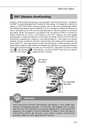
... By the way, if you have to click the DOT button to apply the DOT function. There will be powered only when users' PC runs huge amount of CPU/ GPU while running programs, and to overclock regularly first. Dual Core Center DOT (Dynamic OverClocking) Dynamic Overclocking Technology... is exceed the default threshold for a time, it will speed up the CPU and fan automatically to make the system run smoother and faster. When the motherboard detects that the loading of overclocking options. We suggest...
... By the way, if you have to click the DOT button to apply the DOT function. There will be powered only when users' PC runs huge amount of CPU/ GPU while running programs, and to overclock regularly first. Dual Core Center DOT (Dynamic OverClocking) Dynamic Overclocking Technology... is exceed the default threshold for a time, it will speed up the CPU and fan automatically to make the system run smoother and faster. When the motherboard detects that the loading of overclocking options. We suggest...

