

User Guide
Page 3
... on a reliable flat surface before setting it . Lay this User's Manual for air convection hence protects the equip- Do not place anything over the power cord. 8. Never pour any add-on the equipment should be - fore connecting the equipment to User's Manual. † The equipment has dropped and... damaged. † The equipment has obvious sign of the power source and adjust properly 110/220V be noted. 10. If any of expl os i on the enclosure are for future reference. 3. CAUT ION: ...
... on a reliable flat surface before setting it . Lay this User's Manual for air convection hence protects the equip- Do not place anything over the power cord. 8. Never pour any add-on the equipment should be - fore connecting the equipment to User's Manual. † The equipment has dropped and... damaged. † The equipment has obvious sign of the power source and adjust properly 110/220V be noted. 10. If any of expl os i on the enclosure are for future reference. 3. CAUT ION: ...
User Guide
Page 4
... into an outlet on a circuit different from that to provide reasonable protection against harmful interference in order to radio communications. Notice 2 Shielded interface cables and A.C. power cord, if any, must accept any interference received, including interference that interference will not occur in accordance with the instructions, may cause undesired operation. Micro...
... into an outlet on a circuit different from that to provide reasonable protection against harmful interference in order to radio communications. Notice 2 Shielded interface cables and A.C. power cord, if any, must accept any interference received, including interference that interference will not occur in accordance with the instructions, may cause undesired operation. Micro...
User Guide
Page 8
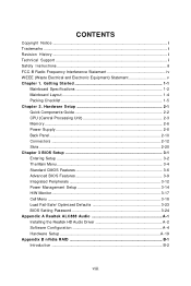
...(Waste Electrical and Electronic Equipment) Statement v Chapter 1. Hardware Setup 2-1 Quick Components Guide 2-2 CPU (Central Processing Unit 2-3 Memory ...2-6 Power Supply ...2-8 Back Panel ...2-10 Connectors ...2-12 Slots ...2-20 Chapter 3 BIOS Setup 3-1 Entering Setup ...3-2 The Main Menu ...3-4 Standard CMOS... Features 3-6 Advanced BIOS Features 3-9 Integrated Peripherals 3-12 Power Management Setup 3-14 H/W Monitor ...3-17 Cell Menu ...3-18 Load Fail-Safe/ Optimized Defaults 3-23 BIOS Setting Password 3-24 ...
...(Waste Electrical and Electronic Equipment) Statement v Chapter 1. Hardware Setup 2-1 Quick Components Guide 2-2 CPU (Central Processing Unit 2-3 Memory ...2-6 Power Supply ...2-8 Back Panel ...2-10 Connectors ...2-12 Slots ...2-20 Chapter 3 BIOS Setup 3-1 Entering Setup ...3-2 The Main Menu ...3-4 Standard CMOS... Features 3-6 Advanced BIOS Features 3-9 Integrated Peripherals 3-12 Power Management Setup 3-14 H/W Monitor ...3-17 Cell Menu ...3-18 Load Fail-Safe/ Optimized Defaults 3-23 BIOS Setting Password 3-24 ...
User Guide
Page 14
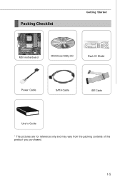
Packing Checklist Getting Started MSI motherboard MSI Driver/Utility CD Back IO Shield Power Cable SATA Cable IDE Cable User's Guide * The pictures are for reference only and may vary from the packing contents of the product you purchased. 1-5
Packing Checklist Getting Started MSI motherboard MSI Driver/Utility CD Back IO Shield Power Cable SATA Cable IDE Cable User's Guide * The pictures are for reference only and may vary from the packing contents of the product you purchased. 1-5
User Guide
Page 17
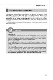
... damage the CPU and system. For the latest information about CPU, please visit http://global.msi.com.tw/index. Replacing the CPU While replacing the CPU, always turn off the ATX power supply or unplug the power supply's power cord from overheating. Any attempt to support overclocking. Hardware Setup CPU (Central Processing Unit) The...
... damage the CPU and system. For the latest information about CPU, please visit http://global.msi.com.tw/index. Replacing the CPU While replacing the CPU, always turn off the ATX power supply or unplug the power supply's power cord from overheating. Any attempt to support overclocking. Hardware Setup CPU (Central Processing Unit) The...
User Guide
Page 18
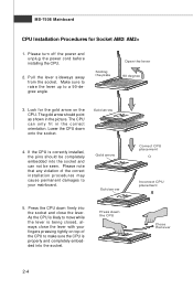
.... Lower the CPU down the CPU Close the lever 2-4 If the CPU is properly and completely embedded into the socket. Please turn off the power and unplug the power cord before installing the CPU. 2. Look for Socket AM2/ AM2+ 1. Pull the lever sideways away from the socket. As the CPU is likely...
.... Lower the CPU down the CPU Close the lever 2-4 If the CPU is properly and completely embedded into the socket. Please turn off the power and unplug the power cord before installing the CPU. 2. Look for Socket AM2/ AM2+ 1. Pull the lever sideways away from the socket. As the CPU is likely...
User Guide
Page 22
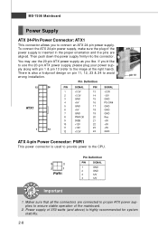
...design on pin 11, 12, 23 & 24 to ensure stable operation of the mainboard. 2. You may use the 20-pin ATX power supply, please plug your power supply along with pin 1 & pin 13 (refer to the image at the right hand). There is inserted in the proper orientation and... the pins are connected to proper ATX power supplies to avoid wrong installation. MS-7508 Mainboard Power Supply ATX 24-Pin Power Connector: ATX1 This connector allows you to the CPU. 4 2 3 1 PWR1 Pin Definition PIN SIGNAL 1 GND 2 GND ...
...design on pin 11, 12, 23 & 24 to ensure stable operation of the mainboard. 2. You may use the 20-pin ATX power supply, please plug your power supply along with pin 1 & pin 13 (refer to the image at the right hand). There is inserted in the proper orientation and... the pins are connected to proper ATX power supplies to avoid wrong installation. MS-7508 Mainboard Power Supply ATX 24-Pin Power Connector: ATX1 This connector allows you to the CPU. 4 2 3 1 PWR1 Pin Definition PIN SIGNAL 1 GND 2 GND ...

User Guide
Page 23
Unplug the AC power cable Unplug the power connector Unplug the power connector Important Mainboard photos shown in this section are very sensitive to ESD, so this kind of your mainboard may vary depending on the model ... while the users intensively swap memory modules under S5 (power-off) states, and the power code is plugged while installing modules. Hardware Setup Important Notification about Power Issue NForce chipset is very sensitive to avoid this situation. Unplug the AC power cable or unplug the power connectors before the 1st installation or during system upgrade...
Unplug the AC power cable Unplug the power connector Unplug the power connector Important Mainboard photos shown in this section are very sensitive to ESD, so this kind of your mainboard may vary depending on the model ... while the users intensively swap memory modules under S5 (power-off) states, and the power code is plugged while installing modules. Hardware Setup Important Notification about Power Issue NForce chipset is very sensitive to avoid this situation. Unplug the AC power cable or unplug the power connectors before the 1st installation or during system upgrade...
User Guide
Page 24
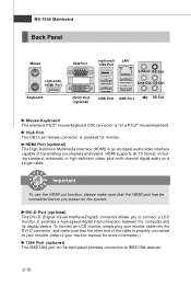
...) The IEEE1394 port on the back panel provides connection to connect a LCD monitor. DVI-D Port (optional) The DVI-D (Digital Visual Interface-Digital) connector allows you power-on a single cable. It provides a high-speed digital interconnection between the computer and its display device. MS-7508 Mainboard Back Panel Mouse (optional) HDMI Port...
...) The IEEE1394 port on the back panel provides connection to connect a LCD monitor. DVI-D Port (optional) The DVI-D (Digital Visual Interface-Digital) connector allows you power-on a single cable. It provides a high-speed digital interconnection between the computer and its display device. MS-7508 Mainboard Back Panel Mouse (optional) HDMI Port...
User Guide
Page 28
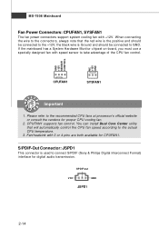
... Digital Interconnect Format) interface for digital audio transmission. GND +12V SENSOR CONTROL NC +12V GND CPUFAN1 SYSFAN1 Important 1. MS-7508 Mainboard Fan Power Connectors: CPUFAN1, SYSFAN1 The fan power connectors support system cooling fan with speed sensor to the recommended CPU fans at processor's official website or consult the vendors for CPUFAN1...
... Digital Interconnect Format) interface for digital audio transmission. GND +12V SENSOR CONTROL NC +12V GND CPUFAN1 SYSFAN1 Important 1. MS-7508 Mainboard Fan Power Connectors: CPUFAN1, SYSFAN1 The fan power connectors support system cooling fan with speed sensor to the recommended CPU fans at processor's official website or consult the vendors for CPUFAN1...
User Guide
Page 31
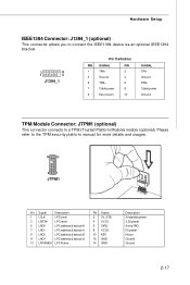
... to connect the IEEE1394 device via an optional IEEE1394 bracket. 2 10 1 9 J1394_1 Pin Definition PIN SIGNAL PIN 1 TPA+ 2 3 Ground 4 5 TPB+ 6 7 Cable power 8 9 Key (no pin) 10 SIGNAL TPAGround TPBCable power Ground TPM Module Connector: JTPM1 (optional) This connector connects to the TPM security platform manual for more details and usages. 14 13... pin2 11 LAD3 LPC address & data pin3 13 LFRAME# LPCFrame Pin Signal 2 3V_STB 4 VCC3 6 SIRQ 8 VCC5 10 KEY 12 GND 14 GND Description 3V standby power 3.3V power Serial IRQ 5V power No pin Ground Ground 2-17
... to connect the IEEE1394 device via an optional IEEE1394 bracket. 2 10 1 9 J1394_1 Pin Definition PIN SIGNAL PIN 1 TPA+ 2 3 Ground 4 5 TPB+ 6 7 Cable power 8 9 Key (no pin) 10 SIGNAL TPAGround TPBCable power Ground TPM Module Connector: JTPM1 (optional) This connector connects to the TPM security platform manual for more details and usages. 14 13... pin2 11 LAD3 LPC address & data pin3 13 LFRAME# LPCFrame Pin Signal 2 3V_STB 4 VCC3 6 SIRQ 8 VCC5 10 KEY 12 GND 14 GND Description 3V standby power 3.3V power Serial IRQ 5V power No pin Ground Ground 2-17
User Guide
Page 32
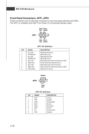
... JFP2 Pin Definition PIN SIGNAL 1 GND 2 SPK- 3 SLED 4 BUZ+ 5 PLED 6 BUZ- 7 NC 8 SPK+ DESCRIPTION Ground SpeakerSuspend LED Buzzer+ Power LED BuzzerNo connection Speaker+ 2-18 Power Power LED Switch - + JFP1 2 1 10 9 + - - + HDD Reset LED Switch JFP1 Pin Definition PIN SIGNAL 1 HD_LED + 2 FP PW R/SLP 3 HD_LED - 4 FP PW R/SLP 5... active LED MSG LED pull-up Reset Switch low reference pull-down to GND Power Switch high reference pull-up Reset Switch high reference pull-up Power Switch low reference pull-down to the front panel switches and LEDs. The JFP1...
... JFP2 Pin Definition PIN SIGNAL 1 GND 2 SPK- 3 SLED 4 BUZ+ 5 PLED 6 BUZ- 7 NC 8 SPK+ DESCRIPTION Ground SpeakerSuspend LED Buzzer+ Power LED BuzzerNo connection Speaker+ 2-18 Power Power LED Switch - + JFP1 2 1 10 9 + - - + HDD Reset LED Switch JFP1 Pin Definition PIN SIGNAL 1 HD_LED + 2 FP PW R/SLP 3 HD_LED - 4 FP PW R/SLP 5... active LED MSG LED pull-up Reset Switch low reference pull-down to GND Power Switch high reference pull-up Reset Switch high reference pull-up Power Switch low reference pull-down to the front panel switches and LEDs. The JFP1...

User Guide
Page 33
W ith the CMOS RAM, the system can clear CMOS by shorting 2-3 pin while the system is a CMOS RAM onboard that has a power supply from an external battery to keep the data of system configuration. Then return to clear data. Avoid clearing the CMOS while the system is turned on ; If you want to clear the system configuration, set the jumper to 1-2 pin position. it is on . Hardware Setup Jumper Clear CMOS Jumper: JVBAT1 There is off. JVBAT1 1 3 1 Keep Data 3 1 Clear Data Important You can automatically boot OS every time it will damage the mainboard. 2-19
W ith the CMOS RAM, the system can clear CMOS by shorting 2-3 pin while the system is a CMOS RAM onboard that has a power supply from an external battery to keep the data of system configuration. Then return to clear data. Avoid clearing the CMOS while the system is turned on ; If you want to clear the system configuration, set the jumper to 1-2 pin position. it is on . Hardware Setup Jumper Clear CMOS Jumper: JVBAT1 There is off. JVBAT1 1 3 1 Keep Data 3 1 Clear Data Important You can automatically boot OS every time it will damage the mainboard. 2-19
User Guide
Page 34
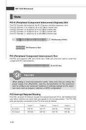
... add-on cards that comply with PCI specifications. 32-bit PCI Slot Important When adding or removing expansion cards, make sure that you unplug the power supply first. The PCI Express x 1 supports up to 2.0 GB/s transfer rate. Meanwhile, read the documentation for the expansion card, such as follows: PCI Slot 1 PCI...
... add-on cards that comply with PCI specifications. 32-bit PCI Slot Important When adding or removing expansion cards, make sure that you unplug the power supply first. The PCI Express x 1 supports up to 2.0 GB/s transfer rate. Meanwhile, read the documentation for the expansion card, such as follows: PCI Slot 1 PCI...
User Guide
Page 36
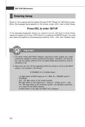
... held for better system performance. It is the BIOS version. W hen the message below appears on the computer and the system will start POST (Power On Self Test) process. The items under continuous update for reference only. 2. Press DEL to enter SETUP If the message disappears before you respond ... OFF and On or pressing the RESET button. V1.0 refers to the BIOS version. 013008 refers to enter Setup. MS-7508 Mainboard Entering Setup Power on the screen, press key to the date this chapter are under each BIOS category described in the format: A7508NMS V1.0 013008 where: 1st...
... held for better system performance. It is the BIOS version. W hen the message below appears on the computer and the system will start POST (Power On Self Test) process. The items under continuous update for reference only. 2. Press DEL to enter SETUP If the message disappears before you respond ... OFF and On or pressing the RESET button. V1.0 refers to the BIOS version. 013008 refers to enter Setup. MS-7508 Mainboard Entering Setup Power on the screen, press key to the date this chapter are under each BIOS category described in the format: A7508NMS V1.0 013008 where: 1st...
User Guide
Page 38
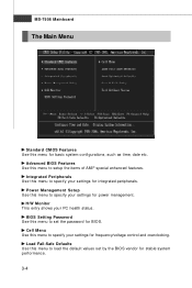
Power Management Setup Use this menu to load the default values set the password for stable system performance. 3-4 Load Fail-Safe Defaults Use this menu to ... specify your settings for basic system configurations, such as time, date etc. MS-7508 Mainboard The Main Menu Standard CMOS Features Use this menu for power management. Integrated Peripherals Use this menu to set by the BIOS vendor for BIOS. H/W Monitor This entry shows your settings for integrated peripherals. Cell Menu...
Power Management Setup Use this menu to load the default values set the password for stable system performance. 3-4 Load Fail-Safe Defaults Use this menu to ... specify your settings for basic system configurations, such as time, date etc. MS-7508 Mainboard The Main Menu Standard CMOS Features Use this menu for power management. Integrated Peripherals Use this menu to set by the BIOS vendor for BIOS. H/W Monitor This entry shows your settings for integrated peripherals. Cell Menu...
User Guide
Page 43
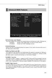
... at boot. [Disabled] Shows the POST messages at boot. Setting to [On] will allow users to run in APIC mode. IOAPIC Function This field is powered on the Num Lock key when the system is used for the system. Due to compliance with PC2001 design guide, the system is... powered on the boot-up Num-Lock LED This setting is to set the Num Lock status when the system is able to use , consult the ...
... at boot. [Disabled] Shows the POST messages at boot. Setting to [On] will allow users to run in APIC mode. IOAPIC Function This field is powered on the Num Lock key when the system is used for the system. Due to compliance with PC2001 design guide, the system is... powered on the boot-up Num-Lock LED This setting is to set the Num Lock status when the system is able to use , consult the ...
User Guide
Page 48
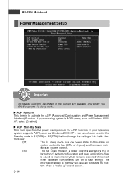
... described in S1(POS) or S3(STR) fashion through the setting of system configuration and open applications/files is saved to main memory that remains powered while most other hardware components turn off to enter the Standby mode in this section are : [S1] The S1 sleep mode is a low...- Set- tings are available only when your operating system supports ACPI, such as W indows 2000/ XP, select [Enabled]. ACPI Standby State This item specifies the power saving modes for ACPI function. In this state, no system context is to restore the system when a "wake up" event occurs. 3-14
... described in S1(POS) or S3(STR) fashion through the setting of system configuration and open applications/files is saved to main memory that remains powered while most other hardware components turn off to enter the Standby mode in this section are : [S1] The S1 sleep mode is a low...- Set- tings are available only when your operating system supports ACPI, such as W indows 2000/ XP, select [Enabled]. ACPI Standby State This item specifies the power saving modes for ACPI function. In this state, no system context is to restore the system when a "wake up" event occurs. 3-14
User Guide
Page 49
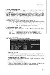
...Event By Setting to [BIOS] activates the following fields, and use the following sub-menu appears. Settings are : [Off] Always leaves the computer in the power off state. [On] Always leaves the computer in this field. Wake Up Event Setup Press and the following fields to [OS], the wake up events... will reboot after resuming from S3 sleep state. The system resume time is shortened when you press the power button, the computer enters the suspend/sleep mode, but if the button is pressed for more than four seconds, the computer is turned off button...
...Event By Setting to [BIOS] activates the following fields, and use the following sub-menu appears. Settings are : [Off] Always leaves the computer in the power off state. [On] Always leaves the computer in this field. Wake Up Event Setup Press and the following fields to [OS], the wake up events... will reboot after resuming from S3 sleep state. The system resume time is shortened when you press the power button, the computer enters the suspend/sleep mode, but if the button is pressed for more than four seconds, the computer is turned off button...
User Guide
Page 50
... Onboard LAN This controls how and whether the system can be awakened from the power saving modes through any event on PCIE device. Resume By PCI-E Device W ...[Enabled], the feature allows your system to enable or disable the feature of the PS/2 mouse is used to be powered on by the devices installed in LAN port. Resume By PCI Device (PM E#) W hen set to [Enabled],... the feature allows your system to be awakened from what power saving modes when input signal of booting up the system on a scheduled time/date. 3-16 Resume By RTC Alarm...
... Onboard LAN This controls how and whether the system can be awakened from the power saving modes through any event on PCIE device. Resume By PCI-E Device W ...[Enabled], the feature allows your system to enable or disable the feature of the PS/2 mouse is used to be powered on by the devices installed in LAN port. Resume By PCI Device (PM E#) W hen set to [Enabled],... the feature allows your system to be awakened from what power saving modes when input signal of booting up the system on a scheduled time/date. 3-16 Resume By RTC Alarm...

