

User Guide
Page 4
... to try to correct the interference by the party responsible for a Class B digital device, pursuant to Part 15 of the FCC Rules. Micro-Star International MS-7367 This device complies with Part 15 of the measures listed below. † Reorient or relocate the receiving antenna. † Increase the separation between the equipment...
... to try to correct the interference by the party responsible for a Class B digital device, pursuant to Part 15 of the FCC Rules. Micro-Star International MS-7367 This device complies with Part 15 of the measures listed below. † Reorient or relocate the receiving antenna. † Increase the separation between the equipment...
User Guide
Page 10
Designed to fit the advanced AM D® Athlon 64 X2/ Athlon 64 processor, the K9AGM3 Series deliver a high performance and professional desktop platform solution. 1-1 The K9AGM3 Series mainboards are based on ATi® 690G/ 690V & SB600 chipsets for choosing the K9AGM3 Series (MS-7367 v1.X) Micro-AT X mainboard. Getting Started Chapter 1 Getting Started Thank you for optimal system efficiency.
Designed to fit the advanced AM D® Athlon 64 X2/ Athlon 64 processor, the K9AGM3 Series deliver a high performance and professional desktop platform solution. 1-1 The K9AGM3 Series mainboards are based on ATi® 690G/ 690V & SB600 chipsets for choosing the K9AGM3 Series (MS-7367 v1.X) Micro-AT X mainboard. Getting Started Chapter 1 Getting Started Thank you for optimal system efficiency.

User Guide
Page 11
...Optional) - Supports 10/100/1000 Fast Ethernet by Realtek 8101E (optional) - Supports storage and data transfers at up to 300MB/s Floppy - 1 floppy port - MS-7367 Mainboard Mainboard Specifications Processor Support - t w / inde x . South Bridge: SB600 chipset Memory Support - DDR2 800/667/533 DRAM (240pin/ 1.8V) -... Ultra DMA 66/100/133 mode - Supports 1 FDD with Fan Speed Control (For the latest information about CPU, please visit http://global.msi. Transfer rate is up to 400Mbps - AMD® Athlon64 / Athlon64 X2 processors in AM2 package - php?f u nc =c puf orm...
...Optional) - Supports 10/100/1000 Fast Ethernet by Realtek 8101E (optional) - Supports storage and data transfers at up to 300MB/s Floppy - 1 floppy port - MS-7367 Mainboard Mainboard Specifications Processor Support - t w / inde x . South Bridge: SB600 chipset Memory Support - DDR2 800/667/533 DRAM (240pin/ 1.8V) -... Ultra DMA 66/100/133 mode - Supports 1 FDD with Fan Speed Control (For the latest information about CPU, please visit http://global.msi. Transfer rate is up to 400Mbps - AMD® Athlon64 / Athlon64 X2 processors in AM2 package - php?f u nc =c puf orm...

User Guide
Page 13
ATX Mainboard 1-4 SATA4 SATA1 SATA3 SATA2 MS-7367 Mainboard Mainboard Layout DIMM1 DIMM3 DIMM2 DIMM4 FDD 1 JCI 1 ATX1 IDE 1 To p : mouse Bo ttom: ke yboard CPUFAN1 I/O HDMI Port JCOM1(optional) Top: VGA Po ... PCI _EX2 RS690G/RS690V 1394 Chip Audio codec PCI _EX16 PCI1 PCI 2 JBAT1 BATT + SB600 SYSFAN JAU D1 JCD1 SPDOUT1 JUSB1 JUSB2 JU SB3 JFP1 K9AGM3 Series (MS-7367 v1.X) Micro-
ATX Mainboard 1-4 SATA4 SATA1 SATA3 SATA2 MS-7367 Mainboard Mainboard Layout DIMM1 DIMM3 DIMM2 DIMM4 FDD 1 JCI 1 ATX1 IDE 1 To p : mouse Bo ttom: ke yboard CPUFAN1 I/O HDMI Port JCOM1(optional) Top: VGA Po ... PCI _EX2 RS690G/RS690V 1394 Chip Audio codec PCI _EX16 PCI1 PCI 2 JBAT1 BATT + SB600 SYSFAN JAU D1 JCD1 SPDOUT1 JUSB1 JUSB2 JU SB3 JFP1 K9AGM3 Series (MS-7367 v1.X) Micro-

User Guide
Page 18
MS-7367 Mainboard CPU Installation Procedures for the gold arrow on top of the correct installation procedures may cause permanent damages to a 90-degree angle. Make sure ...
MS-7367 Mainboard CPU Installation Procedures for the gold arrow on top of the correct installation procedures may cause permanent damages to a 90-degree angle. Make sure ...
User Guide
Page 20
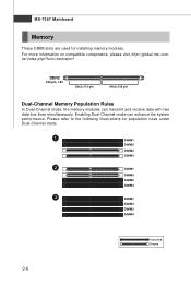
For more information on compatible components, please visit http://global.msi.com. Enabling Dual-Channel mode can transmit and receive data with two data bus lines simultaneously. Please refer to the following illustrations for installing memory modules. MS-7367 Mainboard Memory These DIMM slots are used for population rules under Dual-Channel mode. 1 DIMM1...
For more information on compatible components, please visit http://global.msi.com. Enabling Dual-Channel mode can transmit and receive data with two data bus lines simultaneously. Please refer to the following illustrations for installing memory modules. MS-7367 Mainboard Memory These DIMM slots are used for population rules under Dual-Channel mode. 1 DIMM1...

User Guide
Page 22
... sure that all the connectors are aligned. If you'd like . To connect the ATX 24-pin power supply, make sure the plug of the mainboard. 2. MS-7367 Mainboard Power Supply ATX 24-Pin Power Connector: ATX1 This connector allows you to use the 20-pin ATX power supply as you like to...
... sure that all the connectors are aligned. If you'd like . To connect the ATX 24-pin power supply, make sure the plug of the mainboard. 2. MS-7367 Mainboard Power Supply ATX 24-Pin Power Connector: ATX1 This connector allows you to use the 20-pin ATX power supply as you like to...
User Guide
Page 24
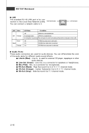
...) - Off 10 Mbit/sec data rate is selected. You can connect a network cable to the Local Area Network (LAN). Center/ Subwoofer Out in 4/ 5.1/ 7.1 channel mode. MS-7367 Mainboard LAN The standard RJ-45 LAN jack is for microphones. On 100 Mbit/sec data rate is selected. Rear-Surround Out in 5.1/ 7.1 channel mode...
...) - Off 10 Mbit/sec data rate is selected. You can connect a network cable to the Local Area Network (LAN). Center/ Subwoofer Out in 4/ 5.1/ 7.1 channel mode. MS-7367 Mainboard LAN The standard RJ-45 LAN jack is for microphones. On 100 Mbit/sec data rate is selected. Rear-Surround Out in 5.1/ 7.1 channel mode...
User Guide
Page 26
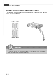
Each connector can connect to one Serial ATA device. MS-7367 Mainboard Serial ATA Connector: SATA1/ SATA2/ SATA3/ SATA4 This connector is a high-speed Serial ATA interface port. Otherwise, data loss may occur during transmission. 2-12 SATA1 SATA2 SATA4 SATA3 Important Please do not fold the Serial ATA cable into 90-degree angle.
Each connector can connect to one Serial ATA device. MS-7367 Mainboard Serial ATA Connector: SATA1/ SATA2/ SATA3/ SATA4 This connector is a high-speed Serial ATA interface port. Otherwise, data loss may occur during transmission. 2-12 SATA1 SATA2 SATA4 SATA3 Important Please do not fold the Serial ATA cable into 90-degree angle.

User Guide
Page 28
... Left channel audio signal to front panel 10 AUD_RET_L Left channel audio signal return from front panel 7 HP_ON Reserved for electrical connection to GND Reserved. MS-7367 Mainboard Front Panel Audio Connector: JAUD1 This connector allows you to connect the front panel audio and is compliant with Intel® Front Panel I /O Connectivity...
... Left channel audio signal to front panel 10 AUD_RET_L Left channel audio signal return from front panel 7 HP_ON Reserved for electrical connection to GND Reserved. MS-7367 Mainboard Front Panel Audio Connector: JAUD1 This connector allows you to connect the front panel audio and is compliant with Intel® Front Panel I /O Connectivity...

User Guide
Page 30
... two types of the TVs. 2-16 Select the appropriate one TV only. Users have to choose either the RCA Composite or the S-Video to connect. MS-7367 Mainboard TV-Out Connector: JTV1 (Optional) This connector is prohibited and may lead to the malfunction of TV-Out connectors: S-Video and RCA Composite connectors...
... two types of the TVs. 2-16 Select the appropriate one TV only. Users have to choose either the RCA Composite or the S-Video to connect. MS-7367 Mainboard TV-Out Connector: JTV1 (Optional) This connector is prohibited and may lead to the malfunction of TV-Out connectors: S-Video and RCA Composite connectors...
User Guide
Page 32
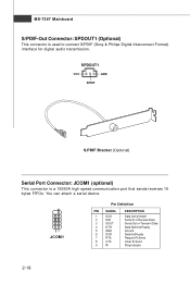
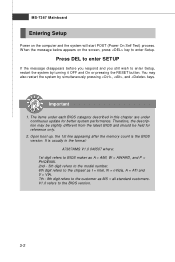
... In or Receive Data Serial Out or Transmit Data Data Terminal Ready Ground Data Set Ready Request To Send Clear To Send Ring Indicate 2-18 MS-7367 Mainboard S/PDIF-Out Connector: SPDOUT1 (Optional) This connector is a 16550A high speed communication port that sends/receives 16 bytes FIFOs.
... In or Receive Data Serial Out or Transmit Data Data Terminal Ready Ground Data Set Ready Request To Send Clear To Send Ring Indicate 2-18 MS-7367 Mainboard S/PDIF-Out Connector: SPDOUT1 (Optional) This connector is a 16550A high speed communication port that sends/receives 16 bytes FIFOs.

User Guide
Page 34
.... 2-20 PCI Express x16 slot PCI Express x1 Slot Important When adding or removing expansion cards, make sure that you unplug the power supply first. MS-7367 Mainboard Slots PCI (Peripheral Component Interconnect) Express Slot The PCI Express slot supports the PCI Express interface expansion card.
.... 2-20 PCI Express x16 slot PCI Express x1 Slot Important When adding or removing expansion cards, make sure that you unplug the power supply first. MS-7367 Mainboard Slots PCI (Peripheral Component Interconnect) Express Slot The PCI Express slot supports the PCI Express interface expansion card.
User Guide
Page 37
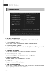
MS-7367 Mainboard Entering Setup Power on the screen, press key to the BIOS version. 3-2 You may be slightly different from the latest BIOS and should be ... digit refers to BIOS maker as A = AMI, W = AWARD, and P = PHOENIX. 2nd - 5th digit refers to the model number. 6th digit refers to the chipset as MS = all standard customers.
MS-7367 Mainboard Entering Setup Power on the screen, press key to the BIOS version. 3-2 You may be slightly different from the latest BIOS and should be ... digit refers to BIOS maker as A = AMI, W = AWARD, and P = PHOENIX. 2nd - 5th digit refers to the model number. 6th digit refers to the chipset as MS = all standard customers.
User Guide
Page 39
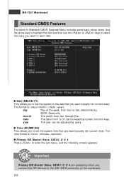
... of AMI® special enhanced features. Advanced Chipset Features Use this menu to change the values in the chipset registers and optimize your system's performance. MS-7367 Mainboard The Main Menu Standard CMOS Features Use this menu to specify your settings for integrated peripherals. Advanced BIOS Features Use this menu for basic...
... of AMI® special enhanced features. Advanced Chipset Features Use this menu to change the values in the chipset registers and optimize your system's performance. MS-7367 Mainboard The Main Menu Standard CMOS Features Use this menu to specify your settings for integrated peripherals. Advanced BIOS Features Use this menu for basic...
User Guide
Page 41
.../ 2/ 3/ 4 Press to 31 can be keyed by numeric function keys. year The year can be adjusted by BIOS. The format is . The time format is . MS-7367 Mainboard Standard CMOS Features The items in Standard CMOS Features Menu includes some basic setup items. Use the arrow keys to highlight the item and...
.../ 2/ 3/ 4 Press to 31 can be keyed by numeric function keys. year The year can be adjusted by BIOS. The format is . The time format is . MS-7367 Mainboard Standard CMOS Features The items in Standard CMOS Features Menu includes some basic setup items. Use the arrow keys to highlight the item and...
User Guide
Page 43
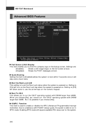
... disable the APIC (Advanced Programmable Interrupt Controller). W hen you choose [No], you choose [Yes]. Setting to [Off] will expand available IRQ resources for the system. 3-8 MS-7367 Mainboard Advanced BIOS Features Full Screen LOGO Display This item enables you to run in APIC mode.
... disable the APIC (Advanced Programmable Interrupt Controller). W hen you choose [No], you choose [Yes]. Setting to [Off] will expand available IRQ resources for the system. 3-8 MS-7367 Mainboard Advanced BIOS Features Full Screen LOGO Display This item enables you to run in APIC mode.
User Guide
Page 45
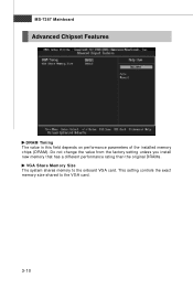
This setting controls the exact memory size shared to the onboard VGA card. Do not change the value from the factory setting unless you install new memory that has a different performance rating than the original DRAMs. VGA Share Memory Size The system shares memory to the VGA card. 3-10 MS-7367 Mainboard Advanced Chipset Features DRAM Timing The value in this field depends on performance parameters of the installed memory chips (DRAM).
This setting controls the exact memory size shared to the onboard VGA card. Do not change the value from the factory setting unless you install new memory that has a different performance rating than the original DRAMs. VGA Share Memory Size The system shares memory to the VGA card. 3-10 MS-7367 Mainboard Advanced Chipset Features DRAM Timing The value in this field depends on performance parameters of the installed memory chips (DRAM).

User Guide
Page 47
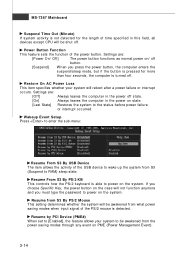
Before configure the RAID set, you to enable/ disable BIOS to used to IDE drives. I /O port addresses of the onboard Serial Port. 3-12 OnChip SATA Type This item is used PCI busmastering for the SATA devices. MS-7367 Mainboard PCI IDE BusMaster This item allows you have to enter the sub-menu: COM Port This item specifies the base I /O Devices Configuration Press to choose the RAID for reading/ writing to define the SATA type.
Before configure the RAID set, you to enable/ disable BIOS to used to IDE drives. I /O port addresses of the onboard Serial Port. 3-12 OnChip SATA Type This item is used PCI busmastering for the SATA devices. MS-7367 Mainboard PCI IDE BusMaster This item allows you have to enter the sub-menu: COM Port This item specifies the base I /O Devices Configuration Press to choose the RAID for reading/ writing to define the SATA type.
User Guide
Page 49
... computer in this field, all devices except CPU will reboot after a power failure or interrupt occurs. Wakeup Event Setup Press to power on the system. MS-7367 Mainboard Suspend Time Out (Minute) If system activity is not detected for more than four seconds, the computer is turned off . Resume by PCI Device...
... computer in this field, all devices except CPU will reboot after a power failure or interrupt occurs. Wakeup Event Setup Press to power on the system. MS-7367 Mainboard Suspend Time Out (Minute) If system activity is not detected for more than four seconds, the computer is turned off . Resume by PCI Device...


