
User Guide
Page 8
... 3 BIOS Setup 3-1 Entering Setup ...3-2 The Main Menu ...3-4 Standard CMOS Features 3-6 Advanced BIOS Features 3-8 Advanced Chipset Features 3-10 Integrated Peripherals 3-11 Power Management Setup 3-13 PNP/PCI Configurations 3-16 H/W Monitor ...3-18 Load Optimized Defaults 3-22 BIOS Setting Password 3-22 Appendix A Realtek ALC888 Audio A-1 Installing the Realtek HD Audio Driver A-2 Setup audio outpur...
... 3 BIOS Setup 3-1 Entering Setup ...3-2 The Main Menu ...3-4 Standard CMOS Features 3-6 Advanced BIOS Features 3-8 Advanced Chipset Features 3-10 Integrated Peripherals 3-11 Power Management Setup 3-13 PNP/PCI Configurations 3-16 H/W Monitor ...3-18 Load Optimized Defaults 3-22 BIOS Setting Password 3-22 Appendix A Realtek ALC888 Audio A-1 Installing the Realtek HD Audio Driver A-2 Setup audio outpur...
User Guide
Page 12
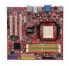
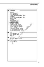
... (optional) - 1 TV-out pinheader (optional) - 1 Front Panel Audio pinheader - 1 CD-in pinheader - 1 SPDIF-out pinheader (optional) - 1 COM port pinheader (optional) - 1 Chassis Intrusion Switch pinheader Slots - 1 PCI Express x16 slot - 1 PCI Express x 1 slot - 2 PCI slots Form Factor - Micro-ATX (24.4cm X 23.0 cm) Mounting - 6 mounting holes 1-3
... (optional) - 1 TV-out pinheader (optional) - 1 Front Panel Audio pinheader - 1 CD-in pinheader - 1 SPDIF-out pinheader (optional) - 1 COM port pinheader (optional) - 1 Chassis Intrusion Switch pinheader Slots - 1 PCI Express x16 slot - 1 PCI Express x 1 slot - 2 PCI slots Form Factor - Micro-ATX (24.4cm X 23.0 cm) Mounting - 6 mounting holes 1-3
User Guide
Page 13
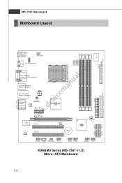
Out B:SS-Ou t JTV1 (option al ) LAN Chip PCI _EX2 PCI _EX16 RS690G/RS690V SYSFAN 1394 Chip PCI1 JBAT1 SB600 Audio codec PCI 2 BATT + JAU D1 JCD1 SPDOUT1 JUSB1 JUSB2 JU SB3 JFP1 K9AGM3 Series (MS-7367 v1.X) Micro- ATX Mainboard 1-4 SATA4 SATA1 SATA3 SATA2 MS-7367 Mainboard Mainboard Layout DIMM1 DIMM3 DIMM2 DIMM4 FDD 1 JCI 1 ATX1...
Out B:SS-Ou t JTV1 (option al ) LAN Chip PCI _EX2 PCI _EX16 RS690G/RS690V SYSFAN 1394 Chip PCI1 JBAT1 SB600 Audio codec PCI 2 BATT + JAU D1 JCD1 SPDOUT1 JUSB1 JUSB2 JU SB3 JFP1 K9AGM3 Series (MS-7367 v1.X) Micro- ATX Mainboard 1-4 SATA4 SATA1 SATA3 SATA2 MS-7367 Mainboard Mainboard Layout DIMM1 DIMM3 DIMM2 DIMM4 FDD 1 JCI 1 ATX1...
User Guide
Page 34
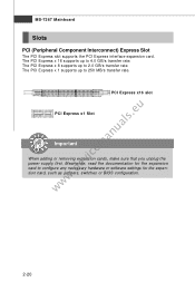
.../s transfer rate. MS-7367 Mainboard Slots PCI (Peripheral Component Interconnect) Express Slot The PCI Express slot supports the PCI Express interface expansion card. The PCI Express x 16 supports up to 4.0 GB/s transfer rate. The PCI Express x 1 supports up to 250 MB/s transfer rate. PCI Express x16 slot www.devicemanuals.eu PCI Express x1 Slot Important When adding...
.../s transfer rate. MS-7367 Mainboard Slots PCI (Peripheral Component Interconnect) Express Slot The PCI Express slot supports the PCI Express interface expansion card. The PCI Express x 16 supports up to 4.0 GB/s transfer rate. The PCI Express x 1 supports up to 250 MB/s transfer rate. PCI Express x16 slot www.devicemanuals.eu PCI Express x1 Slot Important When adding...
User Guide
Page 35
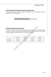
Hardware Setup PCI (Peripheral Component Interconnect) Slot The PCI slot supports LAN card, SCSI card, USB card, and other add-on cards that comply with PCI specifications. 32-bit PCI Slot www.devicemanuals.eu PCI Interrupt Request Routing The IRQ, acronym of interrupt request line and pronounced I-R-Q, are typically connected to the microprocessor. The PCI IRQ pins are hardware lines over which devices can send interrupt signals to the PCI bus pins as follows: PCI Slot 1 PCI Slot 2 Order 1 INT A# INT B# Order 2 INT B# INT C# Order 3 INT C# INT D# Order 4 INT D# INT A# 2-21
Hardware Setup PCI (Peripheral Component Interconnect) Slot The PCI slot supports LAN card, SCSI card, USB card, and other add-on cards that comply with PCI specifications. 32-bit PCI Slot www.devicemanuals.eu PCI Interrupt Request Routing The IRQ, acronym of interrupt request line and pronounced I-R-Q, are typically connected to the microprocessor. The PCI IRQ pins are hardware lines over which devices can send interrupt signals to the PCI bus pins as follows: PCI Slot 1 PCI Slot 2 Order 1 INT A# INT B# Order 2 INT B# INT C# Order 3 INT C# INT D# Order 4 INT D# INT A# 2-21
User Guide
Page 39
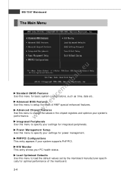
...registers and optimize your system's performance. Advanced Chipset Features Use this menu to specify your settings for power management. PNP/PCI Configurations This entry appears if your PC health status. MS-7367 Mainboard The Main Menu www.devicemanuals.eu Standard CMOS Features... mainboard manufacturer specifically for optimal performance of AMI® special enhanced features. H/W Monitor This entry shows your system supports PnP/PCI. Load Optimized Defaults Use this menu for integrated peripherals. Advanced BIOS Features Use this menu to setup the items of the mainboard...
...registers and optimize your system's performance. Advanced Chipset Features Use this menu to specify your settings for power management. PNP/PCI Configurations This entry appears if your PC health status. MS-7367 Mainboard The Main Menu www.devicemanuals.eu Standard CMOS Features... mainboard manufacturer specifically for optimal performance of AMI® special enhanced features. H/W Monitor This entry shows your system supports PnP/PCI. Load Optimized Defaults Use this menu for integrated peripherals. Advanced BIOS Features Use this menu to setup the items of the mainboard...
User Guide
Page 47
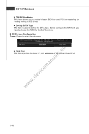
I/O Devices Configuration Press to define the SATA type. OnChip SATA Type This item is used PCI busmastering for the SATA devices. MS-7367 Mainboard PCI IDE BusMaster This item allows you have to choose the RAID for reading/ writing to IDE drives. Before configure the RAID set, you to enable/ disable BIOS to used to enter the sub-menu: www.devicemanuals.eu COM Port This item specifies the base I/O port addresses of the onboard Serial Port. 3-12
I/O Devices Configuration Press to define the SATA type. OnChip SATA Type This item is used PCI busmastering for the SATA devices. MS-7367 Mainboard PCI IDE BusMaster This item allows you have to choose the RAID for reading/ writing to IDE drives. Before configure the RAID set, you to enable/ disable BIOS to used to enter the sub-menu: www.devicemanuals.eu COM Port This item specifies the base I/O port addresses of the onboard Serial Port. 3-12
User Guide
Page 49
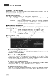
... Event Setup Press to power on / off state. Resume From S3 By PS/2 KB This controls how the PS/2 keyboard is turned off . Resume by PCI Device (PME#) W hen set to [Enabled], the feature allows your system will not function anymore and you must type the password to enter the sub...
... Event Setup Press to power on / off state. Resume From S3 By PS/2 KB This controls how the PS/2 keyboard is turned off . Resume by PCI Device (PME#) W hen set to [Enabled], the feature allows your system will not function anymore and you must type the password to enter the sub...
User Guide
Page 51
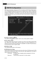
... the CPU itself uses when communicating with its special components. This section covers some very technical items and it is your primary graphics adapter. PCI Latency Timer This item controls how long each IRQ a type depending on the type of the items. IRQ Resources list IRQ 3/4/5/7/9/10/11.../12/14/15 for users to higher values. W hen set each PCI device can conduct transactions for further request. 3-16 PCI Slot 1/2 IRQ This setting specifies IRQ for PCI bus architecture. Reserved The IRQ will enter the sub-menu of device using the IRQ. For better...
... the CPU itself uses when communicating with its special components. This section covers some very technical items and it is your primary graphics adapter. PCI Latency Timer This item controls how long each IRQ a type depending on the type of the items. IRQ Resources list IRQ 3/4/5/7/9/10/11.../12/14/15 for users to higher values. W hen set each PCI device can conduct transactions for further request. 3-16 PCI Slot 1/2 IRQ This setting specifies IRQ for PCI bus architecture. Reserved The IRQ will enter the sub-menu of device using the IRQ. For better...

User Guide
Page 53
...], the system will automatically return to [Reset]. Remember to disable Spread Spectrum function if you are reduced to auto disable the DIMM/PCI slots. W hen set the field to [Enabled] later. Cool'n'Quiet It provides a CPU temperature detecting function to prevent your overclocked... remove (turn off) clocks from overheading due to lock up. MS-7367 Mainboard H/W Monitor www.devicemanuals.eu Spread Spectrum W hen the motherboard's clock generator pulses, the extreme values (spikes) of the pulses are overclocking, because even a slight jitter can introduce a temporary boost ...
...], the system will automatically return to [Reset]. Remember to disable Spread Spectrum function if you are reduced to auto disable the DIMM/PCI slots. W hen set the field to [Enabled] later. Cool'n'Quiet It provides a CPU temperature detecting function to prevent your overclocked... remove (turn off) clocks from overheading due to lock up. MS-7367 Mainboard H/W Monitor www.devicemanuals.eu Spread Spectrum W hen the motherboard's clock generator pulses, the extreme values (spikes) of the pulses are overclocking, because even a slight jitter can introduce a temporary boost ...


