User Guide
Page 2
... FAQ, technical guide, BIOS updates, driver updates, and other countries. func=faqIndex Contact our technical staff at: http://support.msi.com.tw/ ii AMD, Athlon™, Athlon™ XP, Thoroughbred™, and Duron™ are registered trademarks or trade- NVIDIA, the NVIDIA logo, DualNet, and nForce are registered trade- Netware® is given as to make changes without notice...
... FAQ, technical guide, BIOS updates, driver updates, and other countries. func=faqIndex Contact our technical staff at: http://support.msi.com.tw/ ii AMD, Athlon™, Athlon™ XP, Thoroughbred™, and Duron™ are registered trademarks or trade- NVIDIA, the NVIDIA logo, DualNet, and nForce are registered trade- Netware® is given as to make changes without notice...

User Guide
Page 8
...Components Guide 2-2 CPU (Central Processing Unit 2-2 Memory ...2-6 Power Supply ...2-8 Back Panel ...2-9 Connectors ...2-11 Jumpers ...2-19 Slots ...2-20 Chapter 3 BIOS Setup 3-1 Entering Setup ...3-2 The Main Menu ...3-4 Standard CMOS Features 3-6 Advanced BIOS Features 3-8 Advanced Chipset Features 3-10 Integrated Peripherals 3-11 Power Management Setup 3-13 PNP/PCI Configurations 3-16 H/W Monitor ...3-18 Load Optimized Defaults 3-22 BIOS Setting Password 3-22 Appendix A Realtek ALC888 Audio A-1 Installing the Realtek HD Audio Driver A-2 Setup audio outpur to HDMI A-4 Software...
...Components Guide 2-2 CPU (Central Processing Unit 2-2 Memory ...2-6 Power Supply ...2-8 Back Panel ...2-9 Connectors ...2-11 Jumpers ...2-19 Slots ...2-20 Chapter 3 BIOS Setup 3-1 Entering Setup ...3-2 The Main Menu ...3-4 Standard CMOS Features 3-6 Advanced BIOS Features 3-8 Advanced Chipset Features 3-10 Integrated Peripherals 3-11 Power Management Setup 3-13 PNP/PCI Configurations 3-16 H/W Monitor ...3-18 Load Optimized Defaults 3-22 BIOS Setting Password 3-22 Appendix A Realtek ALC888 Audio A-1 Installing the Realtek HD Audio Driver A-2 Setup audio outpur to HDMI A-4 Software...
User Guide
Page 11
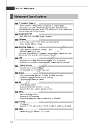
....msi. SATA1~4 support RAID 0/ 1/ 0+1mode 1-2 Supports 4 pin CPU Fan Pin-Header with Azalia 1.0 spec IDE - 1 IDE port by VIA VT6308P (optional) Audio - DDR2 800/667/533 DRAM (240pin/ 1.8V) - 4 DDR2 DIMMs (8GB Max) (For m ore information on compatible components, please visit http:/ / g loba l. c om. North Bridge: AMD® 690G/ 690V (optional) chipset - p hp? Supports Ultra DMA 66/100/133 mode - Supports 10/100/1000 Fast Ethernet by Realtek® ALC888/ ALC883 (optional) - t w / inde x . f unc =t e s t r epor t ) LAN - Controlled...
....msi. SATA1~4 support RAID 0/ 1/ 0+1mode 1-2 Supports 4 pin CPU Fan Pin-Header with Azalia 1.0 spec IDE - 1 IDE port by VIA VT6308P (optional) Audio - DDR2 800/667/533 DRAM (240pin/ 1.8V) - 4 DDR2 DIMMs (8GB Max) (For m ore information on compatible components, please visit http:/ / g loba l. c om. North Bridge: AMD® 690G/ 690V (optional) chipset - p hp? Supports Ultra DMA 66/100/133 mode - Supports 10/100/1000 Fast Ethernet by Realtek® ALC888/ ALC883 (optional) - t w / inde x . f unc =t e s t r epor t ) LAN - Controlled...
User Guide
Page 12
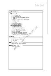
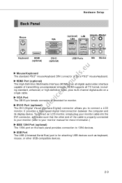
...mouse port - 1 PS/2 keyboard port - 1 HDMI port (optional for AMD® 690G) - 1 VGA port - 1 DVI-D port (optional for AMD® 690G) - 4 USB 2.0 Ports - 1 LAN jack - 6 flexible audio jacks - 1 1394 port (optional) On-Board Pinheaders www.devicemanuals.eu - 3 USB 2.0 pinheaders - 1 1394 pinheader (optional) - 1 TV-out pinheader (optional) - 1 Front Panel Audio pinheader - 1 CD-in pinheader - 1 SPDIF-out pinheader (optional) - 1 COM port pinheader (optional) - 1 Chassis Intrusion Switch pinheader Slots - 1 PCI Express x16 slot - 1 PCI Express x 1 slot - 2 PCI slots Form Factor - Micro-ATX (24...
...mouse port - 1 PS/2 keyboard port - 1 HDMI port (optional for AMD® 690G) - 1 VGA port - 1 DVI-D port (optional for AMD® 690G) - 4 USB 2.0 Ports - 1 LAN jack - 6 flexible audio jacks - 1 1394 port (optional) On-Board Pinheaders www.devicemanuals.eu - 3 USB 2.0 pinheaders - 1 1394 pinheader (optional) - 1 TV-out pinheader (optional) - 1 Front Panel Audio pinheader - 1 CD-in pinheader - 1 SPDIF-out pinheader (optional) - 1 COM port pinheader (optional) - 1 Chassis Intrusion Switch pinheader Slots - 1 PCI Express x16 slot - 1 PCI Express x 1 slot - 2 PCI slots Form Factor - Micro-ATX (24...

User Guide
Page 22
... the mainboard. 2. Power supply of 350 watts (and above) is inserted in the proper orientation and the pins are connected to proper ATX power supplies to use the 20-pin ATX power supply as you like to ensure stable operation of the power supply is highly recommended for system stability. 2-8 MS-7367 Mainboard Power Supply ATX 24-Pin Power Connector: ATX1 This connector allows you to avoid wrong installation. You may use the 20-pin ATX power supply, please plug your power...
... the mainboard. 2. Power supply of 350 watts (and above) is inserted in the proper orientation and the pins are connected to proper ATX power supplies to use the 20-pin ATX power supply as you like to ensure stable operation of the power supply is highly recommended for system stability. 2-8 MS-7367 Mainboard Power Supply ATX 24-Pin Power Connector: ATX1 This connector allows you to avoid wrong installation. You may use the 20-pin ATX power supply, please plug your power...
User Guide
Page 23
... display device. Hardware Setup Back Panel Mouse (optional) LAN Line-In RS-Out VGA 1394 Line-Out CS-Out Keyboard HDMI (optional) DVI-D (optional) USB Ports Mic SS-Out www.devicemanuals.eu Mouse/Keyboard The standard PS/2® mouse/keyboard DIN connector is provided for monitor. USB Port The USB (Universal Serial Bus) port is properly connected to your monitor (refer to your monitor manual for attaching USB devices such as keyboard, mouse, or other end of transmitting uncompressed streams. HDMI supports...
... display device. Hardware Setup Back Panel Mouse (optional) LAN Line-In RS-Out VGA 1394 Line-Out CS-Out Keyboard HDMI (optional) DVI-D (optional) USB Ports Mic SS-Out www.devicemanuals.eu Mouse/Keyboard The standard PS/2® mouse/keyboard DIN connector is provided for monitor. USB Port The USB (Universal Serial Bus) port is properly connected to your monitor (refer to your monitor manual for attaching USB devices such as keyboard, mouse, or other end of transmitting uncompressed streams. HDMI supports...
User Guide
Page 25
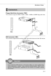
IDE1 Important If you install two IDE devices on the same cable, you must configure the drives separately to IDE device's documentation supplied by setting jumpers. www.devicemanuals.eu FDD1 IDE Connector: IDE1 This connector supports IDE hard disk drives, optical disk drives and other IDE devices. Hardware Setup Connectors Floppy Disk Drive Connector: FDD1 This connector supports 360KB, 720KB, 1.2MB, 1.44MB or 2.88MB floppy disk drive. Refer to master / slave mode by the vendors for jumper setting instructions. 2-11
IDE1 Important If you install two IDE devices on the same cable, you must configure the drives separately to IDE device's documentation supplied by setting jumpers. www.devicemanuals.eu FDD1 IDE Connector: IDE1 This connector supports IDE hard disk drives, optical disk drives and other IDE devices. Hardware Setup Connectors Floppy Disk Drive Connector: FDD1 This connector supports 360KB, 720KB, 1.2MB, 1.44MB or 2.88MB floppy disk drive. Refer to master / slave mode by the vendors for jumper setting instructions. 2-11
User Guide
Page 27
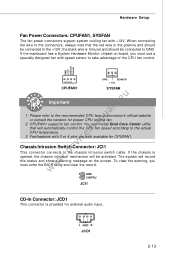
... the mainboard has a System Hardware Monitor chipset on the screen. Chassis Intrusion Switch Connector: JCI1 This connector connects to take advantage of the CPU fan control. W hen connecting the wire to the connectors, always note that will record this status and show a warning message on -board, you must use a specially designed fan with speed sensor to the chassis intrusion switch cable. Fan/heatsink with +12V. Hardware Setup Fan Power Connectors: CPUFAN1, SYSFAN The fan power connectors support system cooling fan with 3 or 4 pins are...
... the mainboard has a System Hardware Monitor chipset on the screen. Chassis Intrusion Switch Connector: JCI1 This connector connects to take advantage of the CPU fan control. W hen connecting the wire to the connectors, always note that will record this status and show a warning message on -board, you must use a specially designed fan with speed sensor to the chassis intrusion switch cable. Fan/heatsink with +12V. Hardware Setup Fan Power Connectors: CPUFAN1, SYSFAN The fan power connectors support system cooling fan with 3 or 4 pins are...
User Guide
Page 28
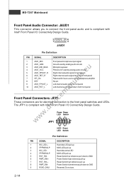
... Reserved for future use . 2-14 Do not use to control headphone amplifier 8 KEY No pin 9 AUD_FPOUT_L Left channel audio signal to front panel 10 AUD_RET_L Left channel audio signal return from front panel Front Panel Connectors: JFP1 These connectors are for electrical connection to the front panel switches and LEDs. MS-7367 Mainboard Front Panel Audio Connector: JAUD1 This connector allows you to connect the front panel audio and is compliant with Intel® Front Panel I /O Connectivity Design Guide.
... Reserved for future use . 2-14 Do not use to control headphone amplifier 8 KEY No pin 9 AUD_FPOUT_L Left channel audio signal to front panel 10 AUD_RET_L Left channel audio signal return from front panel Front Panel Connectors: JFP1 These connectors are for electrical connection to the front panel switches and LEDs. MS-7367 Mainboard Front Panel Audio Connector: JAUD1 This connector allows you to connect the front panel audio and is compliant with Intel® Front Panel I /O Connectivity Design Guide.
User Guide
Page 33
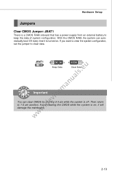
... damage the mainboard. 2-19 Avoid clearing the CMOS while the system is off. W ith the CMOS RAM, the system can clear CMOS by shorting 2-3 pin while the system is on . If you want to clear the system configuration, set the jumper to 1-2 pin position. Then return to clear data. it is a CMOS RAM onboard that has a power supply from an external battery to keep the data of system configuration. Hardware Setup Jumpers Clear CMOS Jumper: JBAT1 There...
... damage the mainboard. 2-19 Avoid clearing the CMOS while the system is off. W ith the CMOS RAM, the system can clear CMOS by shorting 2-3 pin while the system is on . If you want to clear the system configuration, set the jumper to 1-2 pin position. Then return to clear data. it is a CMOS RAM onboard that has a power supply from an external battery to keep the data of system configuration. Hardware Setup Jumpers Clear CMOS Jumper: JBAT1 There...
User Guide
Page 34
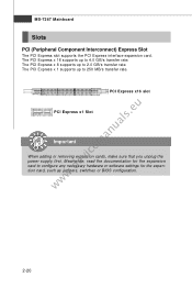
... PCI Express x 16 supports up to 4.0 GB/s transfer rate. The PCI Express x 8 supports up to 2.0 GB/s transfer rate. PCI Express x16 slot www.devicemanuals.eu PCI Express x1 Slot Important When adding or removing expansion cards, make sure that you unplug the power supply first. The PCI Express x 1 supports up to configure any necessary hardware or software settings for the expansion card, such as jumpers, switches or BIOS configuration. 2-20 MS-7367 Mainboard Slots PCI (Peripheral Component Interconnect) Express Slot The PCI Express slot supports the PCI Express...
... PCI Express x 16 supports up to 4.0 GB/s transfer rate. The PCI Express x 8 supports up to 2.0 GB/s transfer rate. PCI Express x16 slot www.devicemanuals.eu PCI Express x1 Slot Important When adding or removing expansion cards, make sure that you unplug the power supply first. The PCI Express x 1 supports up to configure any necessary hardware or software settings for the expansion card, such as jumpers, switches or BIOS configuration. 2-20 MS-7367 Mainboard Slots PCI (Peripheral Component Interconnect) Express Slot The PCI Express slot supports the PCI Express...
User Guide
Page 42
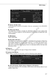
.../ BIOS Version/ M emory Information These items show the CPU information, BIOS version and memory status of floppy drives installed. This allows you to predict hard disk failure. Hard Disk S.M.A.R.T. Floppy A This item allows you connected to activate the S.M.A.R.T. (Self-Monitoring Analysis & Reporting Technology) capability for the hard disks. LBA/Large M ode This allows you to the IDE/SATA www.devicemanuals.eu connector. System Information Press to Auto enables LBA mode if the device supports it and the devices is a utility...
.../ BIOS Version/ M emory Information These items show the CPU information, BIOS version and memory status of floppy drives installed. This allows you to predict hard disk failure. Hard Disk S.M.A.R.T. Floppy A This item allows you connected to activate the S.M.A.R.T. (Self-Monitoring Analysis & Reporting Technology) capability for the hard disks. LBA/Large M ode This allows you to the IDE/SATA www.devicemanuals.eu connector. System Information Press to Auto enables LBA mode if the device supports it and the devices is a utility...
User Guide
Page 46
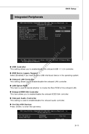
... enable/disable the onboard IEEE1394 controller. LAN Option ROM This item is used to decide whether to use a USB-interfaced device in the operating system. Onboard IEEE1394 Controller This item allows you to enable/disable the onboard USB 1.1/ 2.0 controller. On-Chip ATA Devices Press to enable/disable the onboard LAN controller. Onboard LAN Controller This setting allows you need to invoke the Boot ROM of the onboard LAN. Onboard Audio Controller This setting is used to enable/disable the onboard audio controller. USB Device Legacy Support Select [Enabled] if you to enter...
... enable/disable the onboard IEEE1394 controller. LAN Option ROM This item is used to decide whether to use a USB-interfaced device in the operating system. Onboard IEEE1394 Controller This item allows you to enable/disable the onboard USB 1.1/ 2.0 controller. On-Chip ATA Devices Press to enable/disable the onboard LAN controller. Onboard LAN Controller This setting allows you need to invoke the Boot ROM of the onboard LAN. Onboard Audio Controller This setting is used to enable/disable the onboard audio controller. USB Device Legacy Support Select [Enabled] if you to enter...
User Guide
Page 51
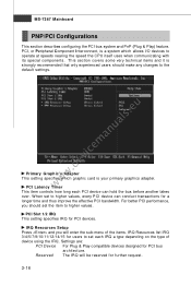
MS-7367 Mainboard PNP/PCI Configurations This section describes configuring the PCI bus system and PnP (Plug & Play) feature. www.devicemanuals.eu Primary Graphic's Adapter This setting specifies which allows I/O devices to the default settings. IRQ Resources Setup Press and you should make any changes to operate at speeds nearing the speed the CPU itself uses when communicating with its special components. PCI Latency Timer This item controls how long each IRQ...
MS-7367 Mainboard PNP/PCI Configurations This section describes configuring the PCI bus system and PnP (Plug & Play) feature. www.devicemanuals.eu Primary Graphic's Adapter This setting specifies which allows I/O devices to the default settings. IRQ Resources Setup Press and you should make any changes to operate at speeds nearing the speed the CPU itself uses when communicating with its special components. PCI Latency Timer This item controls how long each IRQ...

User Guide
Page 53
... heavy working loading. 3-18 The setting of the pulses creates EMI (Electromagnetic Interference). Cool'n'Quiet It provides a CPU temperature detecting function to prevent your overclocked processor to minimize the electromagnetic interference (EMI). If you are overclocking, because even a slight jitter can introduce a temporary boost in clock speed which may just cause your CPU's from empty DIMM/PCI slots to lock up. MS-7367 Mainboard H/W Monitor...
... heavy working loading. 3-18 The setting of the pulses creates EMI (Electromagnetic Interference). Cool'n'Quiet It provides a CPU temperature detecting function to prevent your overclocked processor to minimize the electromagnetic interference (EMI). If you are overclocking, because even a slight jitter can introduce a temporary boost in clock speed which may just cause your CPU's from empty DIMM/PCI slots to lock up. MS-7367 Mainboard H/W Monitor...
User Guide
Page 57
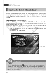
... into the CD-ROM drive. Click here Important The HD Audio Configuration software utility is under continuous update to enhance audio applications. For Windows® XP, you must install W indows® XP Service Pack1 or later before installing the driver. Hence, the program screens shown here in different operating systems. 1. Follow the procedures described below to install the drivers for different operating systems. Installation for Windows 2000/XP...
... into the CD-ROM drive. Click here Important The HD Audio Configuration software utility is under continuous update to enhance audio applications. For Windows® XP, you must install W indows® XP Service Pack1 or later before installing the driver. Hence, the program screens shown here in different operating systems. 1. Follow the procedures described below to install the drivers for different operating systems. Installation for Windows 2000/XP...
User Guide
Page 59
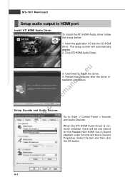
... Sound playback under Sounds and Audio Devices Properties. rectly installed, there will automatically appear. 2. Click Next to : Start -> Control Panel -> Sounds and Audio Devices W hen the ATI HDMI Audio Driver is cor- Restart the computer after the driver installation procedure. www.devicemanuals.eu 3. Setup Sounds and Audio Devices Go to install the driver. 4. MS-7367 Mainboard Setup audio output to HDMI port Install ATI HDMI Audio Driver To install the ATI HDMI Audio driver follow the steps below. 1. Insert the application CD into the CD-ROM drive...
... Sound playback under Sounds and Audio Devices Properties. rectly installed, there will automatically appear. 2. Click Next to : Start -> Control Panel -> Sounds and Audio Devices W hen the ATI HDMI Audio Driver is cor- Restart the computer after the driver installation procedure. www.devicemanuals.eu 3. Setup Sounds and Audio Devices Go to install the driver. 4. MS-7367 Mainboard Setup audio output to HDMI port Install ATI HDMI Audio Driver To install the ATI HDMI Audio driver follow the steps below. 1. Insert the application CD into the CD-ROM drive...
User Guide
Page 79
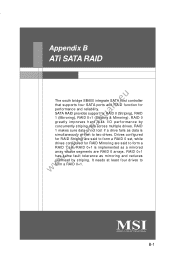
SATA RAID provides support for RAID Mirroring are said to form a RAID 1 set , while drives configured for RAID 0 (Striping), RAID 1 (Mirroring), RAID 0+1 (Striping & Mirroring). Drives configured for RAID Striping are RAID 0 arrays. RAID 0+1 is simultaneously written to form a RAID 0+1. It needs at least four drives to two drives. ATi SATA RAID Appendix B ATi SATA RAID www.devicemanuals.eu The south bridge SB600 integrate SATA host controller that supports four SATA ports and RAID function for performance and reliability. RAID 0+1 has same...
SATA RAID provides support for RAID Mirroring are said to form a RAID 1 set , while drives configured for RAID 0 (Striping), RAID 1 (Mirroring), RAID 0+1 (Striping & Mirroring). Drives configured for RAID Striping are RAID 0 arrays. RAID 0+1 is simultaneously written to form a RAID 0+1. It needs at least four drives to two drives. ATi SATA RAID Appendix B ATi SATA RAID www.devicemanuals.eu The south bridge SB600 integrate SATA host controller that supports four SATA ports and RAID function for performance and reliability. RAID 0+1 has same...
User Guide
Page 86
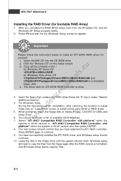
..." on "Load Driver" button to continue. 9. For W indows Vista: During the Operating system installation, after the RAID volume is formatted, and W indows setup starts copying files. W hen prompted, insert the floppy disk or media (Floppy, CD/DVD Or USB) and press Enter. Press ENTER again to install a third party SCSI or RAID driver. Insert the floppy that you complete the RAID BIOS setup, boot from the floppy again after selecting the location to install Vista click...
..." on "Load Driver" button to continue. 9. For W indows Vista: During the Operating system installation, after the RAID volume is formatted, and W indows setup starts copying files. W hen prompted, insert the floppy disk or media (Floppy, CD/DVD Or USB) and press Enter. Press ENTER again to install a third party SCSI or RAID driver. Insert the floppy that you complete the RAID BIOS setup, boot from the floppy again after selecting the location to install Vista click...
User Guide
Page 87
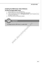
ATi SATA RAID Installing the RAID Driver Under Windows (for Non-bootable RAID Array) 1. The CD will auto-run and the setup screen will be automatically installed. The ATI System Driver includes ATI RAID Driver. 4. Insert the MSI CD into the CD-ROM drive. 2. The driver will appear. 3. Under the Driver tab, click on ATI System Driver. B-9 Important www.devicemanuals.eu You must install the RAID driver to enable RAID.
ATi SATA RAID Installing the RAID Driver Under Windows (for Non-bootable RAID Array) 1. The CD will auto-run and the setup screen will be automatically installed. The ATI System Driver includes ATI RAID Driver. 4. Insert the MSI CD into the CD-ROM drive. 2. The driver will appear. 3. Under the Driver tab, click on ATI System Driver. B-9 Important www.devicemanuals.eu You must install the RAID driver to enable RAID.

