User Guide
Page 10
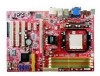
The K9AG Neo2-Digital Series mainboards are based on AMD® 690G & SB600 chipsets for choosing the K9AG Neo2-Digital Series (MS-7368v1.X) ATX mainboard. Designed to fit the advanced AM D® Athlon 64 X2/ Athlon 64 / Sempron AM2 processor, the K9AG Neo2-Digital Series deliver a high performance and professional desktop platform solution. 1-1 Getting Started Chapter 1 Getting Started Thank you for optimal system efficiency.
The K9AG Neo2-Digital Series mainboards are based on AMD® 690G & SB600 chipsets for choosing the K9AG Neo2-Digital Series (MS-7368v1.X) ATX mainboard. Designed to fit the advanced AM D® Athlon 64 X2/ Athlon 64 / Sempron AM2 processor, the K9AG Neo2-Digital Series deliver a high performance and professional desktop platform solution. 1-1 Getting Started Chapter 1 Getting Started Thank you for optimal system efficiency.
User Guide
Page 11
... spec IDE - 1 IDE port by VIA VT6308P (optional) Audio - Supports PIO, Bus Master operation modes SATA - c om . North Bridge: AMD® 690G chipset - MS-7368 Mainboard Mainboard Specifications Processor Support - DDR2 800/667/533 DRAM (8GB Max) - 4 DDR2 DIMMs (240pin / 1.8V) (For more information on compatible...- Supports 4 pin CPU Fan Pin-Header with Fan Speed Control - php ?func =c puf orm Supported FSB - 1000/800/600/400/200 MHz Chipset - Controlled by AMD® SB600 - Supports 2 IEEE1394 ports, transfer rate is up to 5000+ and higher CPU (For the latest information about ...
... spec IDE - 1 IDE port by VIA VT6308P (optional) Audio - Supports PIO, Bus Master operation modes SATA - c om . North Bridge: AMD® 690G chipset - MS-7368 Mainboard Mainboard Specifications Processor Support - DDR2 800/667/533 DRAM (8GB Max) - 4 DDR2 DIMMs (240pin / 1.8V) (For more information on compatible...- Supports 4 pin CPU Fan Pin-Header with Fan Speed Control - php ?func =c puf orm Supported FSB - 1000/800/600/400/200 MHz Chipset - Controlled by AMD® SB600 - Supports 2 IEEE1394 ports, transfer rate is up to 5000+ and higher CPU (For the latest information about ...

User Guide
Page 22
... DIMM slot. DDR2 memory modules are not interchangeable with a 2GB memory module. 2-7 Insert the memory module vertically into the DIM M1 first. - Due to the chipset resource deployment, the system density will automatically close. Volt Notch Important - The memory module has only one notch on the memory module is not backwards...
... DIMM slot. DDR2 memory modules are not interchangeable with a 2GB memory module. 2-7 Insert the memory module vertically into the DIM M1 first. - Due to the chipset resource deployment, the system density will automatically close. Volt Notch Important - The memory module has only one notch on the memory module is not backwards...

User Guide
Page 28
... jack detection resistor network No control Analog Port - the black wire is compliant with speed sensor to GND. If the mainboard has a System Hardware Monitor chipset on-board, you to connect the front panel audio and is Ground and should be connected to take advantage of the CPU fan control. W hen...
... jack detection resistor network No control Analog Port - the black wire is compliant with speed sensor to GND. If the mainboard has a System Hardware Monitor chipset on-board, you to connect the front panel audio and is Ground and should be connected to take advantage of the CPU fan control. W hen...
User Guide
Page 37
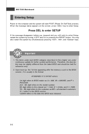
... each BIOS category described in the format: A7368AMS V1.0 041607 where: 1st digit refers to BIOS maker as A = AMI, W = AWARD, and P = PHOENIX. 2nd - 5th digit refers to the model number. 6th digit refers to the chipset as I = Intel, N = nVidia, and A = AMD. 7th - 8th digit refers to the customer as MS = all standard customers. Therefore, the...
... each BIOS category described in the format: A7368AMS V1.0 041607 where: 1st digit refers to BIOS maker as A = AMI, W = AWARD, and P = PHOENIX. 2nd - 5th digit refers to the model number. 6th digit refers to the chipset as I = Intel, N = nVidia, and A = AMD. 7th - 8th digit refers to the customer as MS = all standard customers. Therefore, the...

User Guide
Page 45
... to the onboard VGA card. MPS Table Version This field allows you to select which version to use, consult the vendor of the chipset. To find out which MPS (Multi-Processor Specification) version to it , and will expand available IRQ resources for the operating system. VGA Share Memory The ...
... to the onboard VGA card. MPS Table Version This field allows you to select which version to use, consult the vendor of the chipset. To find out which MPS (Multi-Processor Specification) version to it , and will expand available IRQ resources for the operating system. VGA Share Memory The ...

User Guide
Page 49
... activate the ACPI (Advanced Configuration and Power Management Interface) Function. The information stored in formation of this state, no system context is lost (CPU or chipset) and hardware main- In this field. MS-7368 Mainboard Power Management Setup Important S3-related functions described in this section are : [S1/POS] The S1...
... activate the ACPI (Advanced Configuration and Power Management Interface) Function. The information stored in formation of this state, no system context is lost (CPU or chipset) and hardware main- In this field. MS-7368 Mainboard Power Management Setup Important S3-related functions described in this section are : [S1/POS] The S1...

User Guide
Page 55
... the current clocks of CPU & DDR memory frequency. Readonly. MS-7368 Mainboard Cell Menu Important Change these settings only if you are familiar with the chipset. Read-only. 3-20
... the current clocks of CPU & DDR memory frequency. Readonly. MS-7368 Mainboard Cell Menu Important Change these settings only if you are familiar with the chipset. Read-only. 3-20
User Guide
Page 89
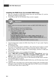
... that contains the RAID driver,Press the "S" key to copy the files from the W indows CD, and the W indows XP Setup program starts. 2. Insert the MSI CD into the CD-ROM drive. 2. W hen prompted, insert the floppy disk or media (Floppy, CD/DVD Or USB) and press Enter. 6. The next.... 5. Leave the disk in the : for Windows XP driver CD \ AM D\A M DDr v\SBD rv\R AID for Windows Vista driver CD \ChipSet\AM D\Packages\Drivers\SBDrv\SB6xx\RAID\x86 and \ChipSet\AMD\Packages\Drivers\SBDrv\SB6xx\RAID\x64 to install Vista click on the Setup screen. 3. Insert the floppy that you complete...
... that contains the RAID driver,Press the "S" key to copy the files from the W indows CD, and the W indows XP Setup program starts. 2. Insert the MSI CD into the CD-ROM drive. 2. W hen prompted, insert the floppy disk or media (Floppy, CD/DVD Or USB) and press Enter. 6. The next.... 5. Leave the disk in the : for Windows XP driver CD \ AM D\A M DDr v\SBD rv\R AID for Windows Vista driver CD \ChipSet\AM D\Packages\Drivers\SBDrv\SB6xx\RAID\x86 and \ChipSet\AMD\Packages\Drivers\SBDrv\SB6xx\RAID\x64 to install Vista click on the Setup screen. 3. Insert the floppy that you complete...