User Guide
Page 5
...-Pin Power Connector: JWR1 2-10 ATX 12V Power Connector: JPW1 2-10 Back Panel ...2-11 Mouse Connector (Green 2-11 Keyboard Connector (Purple 2-11 Serial Port Connector 2-12 USB Connectors 2-12 IEEE1394 Ports (Optional 2-12 RJ-45 LAN Jack 2-13 Audio Port Connectors 2-14 Parallel Port Connector...2-18 Parallel ATA/Serial ATA RAID Connectors controlled by Promise 20579: IDE3/SER1/SER2 (Optional 2-18 Front Panel Audio Connector: JAUD1 2-19 Front USB Connectors: JUSB1/JUSB2 2-20 CD-In Connector: JCD1 2-20 IEEE 1394 Connector: J1394_1 (Optional 2-20 Front Panel Connectors: JFP1/JFP2 2-21...
...-Pin Power Connector: JWR1 2-10 ATX 12V Power Connector: JPW1 2-10 Back Panel ...2-11 Mouse Connector (Green 2-11 Keyboard Connector (Purple 2-11 Serial Port Connector 2-12 USB Connectors 2-12 IEEE1394 Ports (Optional 2-12 RJ-45 LAN Jack 2-13 Audio Port Connectors 2-14 Parallel Port Connector...2-18 Parallel ATA/Serial ATA RAID Connectors controlled by Promise 20579: IDE3/SER1/SER2 (Optional 2-18 Front Panel Audio Connector: JAUD1 2-19 Front USB Connectors: JUSB1/JUSB2 2-20 CD-In Connector: JCD1 2-20 IEEE 1394 Connector: J1394_1 (Optional 2-20 Front Panel Connectors: JFP1/JFP2 2-21...
User Guide
Page 9
Getting Started Getting Started Thank you for digital audio transmission. Designed to fit the advanced AMD® Athlon 64 and Athlon 64 FX processors, the K8T Neo2 delivers a high performance and professional desktop platform solution. 1-1 Getting Started Chapter 1. The K8T Neo2 is based on VIA® K8T800 Pro North Bridge & VT8237 South Bridge chipsets and provides eight USB 2.0 ports for high-speed data transmission, RealTek ALC850 chip for 7.1-channel audio output, and a SPDIF interface for purchasing K8T Neo2 (MS-6702E v1.X) ATX mainboard.
Getting Started Getting Started Thank you for digital audio transmission. Designed to fit the advanced AMD® Athlon 64 and Athlon 64 FX processors, the K8T Neo2 delivers a high performance and professional desktop platform solution. 1-1 Getting Started Chapter 1. The K8T Neo2 is based on VIA® K8T800 Pro North Bridge & VT8237 South Bridge chipsets and provides eight USB 2.0 ports for high-speed data transmission, RealTek ALC850 chip for 7.1-channel audio output, and a SPDIF interface for purchasing K8T Neo2 (MS-6702E v1.X) ATX mainboard.
User Guide
Page 10
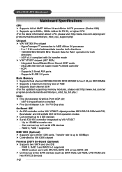
... Sound AC97 audio - HyperTransportTM connection to AMD Athlon 64 processor - 8 or 16 bit control/address/data transfer both directions - Supports 8 USB 2.0 ports Main Memory h Supports Dual channel DDR266/333/400 DDR SDRAM for both directions - 1000/800/600/400/200 MHz "Double Data...channel DDR (For the updated supporting memory modules, please visit http://www.msi.com.tw/ program/products/mainboard/mbd/pro_mbd_trp_list.php.) Slots h One (Accelerated Graphics Port) AGP slot - ACPI - MS-6702E ATX Mainboard Mainboard Specifications CPU h Supports 64-bit AMD® Athlon 64 and...
... Sound AC97 audio - HyperTransportTM connection to AMD Athlon 64 processor - 8 or 16 bit control/address/data transfer both directions - Supports 8 USB 2.0 ports Main Memory h Supports Dual channel DDR266/333/400 DDR SDRAM for both directions - 1000/800/600/400/200 MHz "Double Data...channel DDR (For the updated supporting memory modules, please visit http://www.msi.com.tw/ program/products/mainboard/mbd/pro_mbd_trp_list.php.) Slots h One (Accelerated Graphics Port) AGP slot - ACPI - MS-6702E ATX Mainboard Mainboard Specifications CPU h Supports 64-bit AMD® Athlon 64 and...

User Guide
Page 11
... mainboard provides a Desktop Management Interface (DMI) function which records your mainboard specifications h ACPI, 1.0a, APM1.2, PnP 1.0a, SMBIOS 2.3, USB 2.0, WFM 2.0, Overclock, Boot from USB device Dimension h ATX Form Factor: 30.4 cm (L) x 24.4 cm (W) Mounting h 9 mounting holes MSI Reminds You... 1. To create a bootable RAID volume for SIR/ASKIR/HPSIR - 1 audio port - 1 D-Bracket 2 pinheader - Please note...
... mainboard provides a Desktop Management Interface (DMI) function which records your mainboard specifications h ACPI, 1.0a, APM1.2, PnP 1.0a, SMBIOS 2.3, USB 2.0, WFM 2.0, Overclock, Boot from USB device Dimension h ATX Form Factor: 30.4 cm (L) x 24.4 cm (W) Mounting h 9 mounting holes MSI Reminds You... 1. To create a bootable RAID volume for SIR/ASKIR/HPSIR - 1 audio port - 1 D-Bracket 2 pinheader - Please note...
User Guide
Page 12
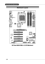
...) SATA2 SATA1 IDE3 BATT + BIOS SER2 JUSB1 JUSB2 JLED1 JIR1 PROMISE (Optional) PDC20579 (Optional) (Optional) JFP2 JFP1 SER1 K8T Neo2 (MS-6702E) v1.X ATX Mainboard PWF_FAN1 PWF_ FAN2 JGS1 J B AT 1 1-4 ATX Power Supply FDD1 MS-6702E ATX Mainboard Mainboard Layout T: mouse B: keyboard CFAN1 DIMM 1 JCASE 1 Winbond W83627THF DIMM 3 DIMM 2 DIMM 4 (Optional) (Optional) JPW1 VIA K8T800...
...) SATA2 SATA1 IDE3 BATT + BIOS SER2 JUSB1 JUSB2 JLED1 JIR1 PROMISE (Optional) PDC20579 (Optional) (Optional) JFP2 JFP1 SER1 K8T Neo2 (MS-6702E) v1.X ATX Mainboard PWF_FAN1 PWF_ FAN2 JGS1 J B AT 1 1-4 ATX Power Supply FDD1 MS-6702E ATX Mainboard Mainboard Layout T: mouse B: keyboard CFAN1 DIMM 1 JCASE 1 Winbond W83627THF DIMM 3 DIMM 2 DIMM 4 (Optional) (Optional) JPW1 VIA K8T800...

User Guide
Page 24
... back panel provides the following connectors: Mouse Parallel SPDIF Out Line-In Line-Out MIC LAN Keyboard COM A Mini 1394 Port (Optional) 1394 Port (Optional) USB Ports Rear Speaker-Out Center/Subwoofer Speaker-Out SPDIF-Out Mouse Connector (Green) The mainboard provides a standard PS/2® mouse mini DIN connector for attaching...
... back panel provides the following connectors: Mouse Parallel SPDIF Out Line-In Line-Out MIC LAN Keyboard COM A Mini 1394 Port (Optional) 1394 Port (Optional) USB Ports Rear Speaker-Out Center/Subwoofer Speaker-Out SPDIF-Out Mouse Connector (Green) The mainboard provides a standard PS/2® mouse mini DIN connector for attaching...

User Guide
Page 25
... serial bus components provide the enhanced PC connectivity for you to connect the IEEE1394 device with external power. MS-6702E ATX Mainboard Serial Port Connector The mainboard offers one 9-pin male DIN connector as keyboard, mouse or other PCs, and ...portable devices. 2-12 IEEE1394 Port (Standard) IEEE1394 Port (Mini) You can plug the USB device directly into the connector. 1 2 3 4 5 6 7 8 USB Ports USB Port Description PIN SIGNAL 1 VCC 2 -Data 0 3 +Data0 4 GND 5 VCC 6 -Data 1 7 +Data 1 8 GND DESCRIPTION...
... serial bus components provide the enhanced PC connectivity for you to connect the IEEE1394 device with external power. MS-6702E ATX Mainboard Serial Port Connector The mainboard offers one 9-pin male DIN connector as keyboard, mouse or other PCs, and ...portable devices. 2-12 IEEE1394 Port (Standard) IEEE1394 Port (Mini) You can plug the USB device directly into the connector. 1 2 3 4 5 6 7 8 USB Ports USB Port Description PIN SIGNAL 1 VCC 2 -Data 0 3 +Data0 4 GND 5 VCC 6 -Data 1 7 +Data 1 8 GND DESCRIPTION...
User Guide
Page 29
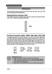
It supports three-pin head connector. GND +12V SENSOR CFAN1 GND +12V SENSOR SFAN1 GND +12V NC PWF_FAN1 GND +12V NC PWF_FAN2 MSI Reminds You... 1. Always consult the vendors for proper CPU cooling fan. 2. You can install Core Center utility that supports 360K, 720K, 1.2M, 1.44M and... to the actual CPU temperature. 3. Please refer to FDD, IDE HDD, case, LAN, USB Ports, IR module and CPU/System FAN. CFAN1 supports the fan control. When connecting the wire to GND. MS-6702E ATX Mainboard Connectors The mainboard provides connectors to connect to the recommend CPU fans at AMD...
It supports three-pin head connector. GND +12V SENSOR CFAN1 GND +12V SENSOR SFAN1 GND +12V NC PWF_FAN1 GND +12V NC PWF_FAN2 MSI Reminds You... 1. Always consult the vendors for proper CPU cooling fan. 2. You can install Core Center utility that supports 360K, 720K, 1.2M, 1.44M and... to the actual CPU temperature. 3. Please refer to FDD, IDE HDD, case, LAN, USB Ports, IR module and CPU/System FAN. CFAN1 supports the fan control. When connecting the wire to GND. MS-6702E ATX Mainboard Connectors The mainboard provides connectors to connect to the recommend CPU fans at AMD...

User Guide
Page 33
...) CD-In Connector: JCD1 L The connector is ideal for CD-ROM audio connector. JUSB1 & JUSB2 Pin Definition 2 10 1 9 JUSB1, JUSB2 (USB 2.0) PIN SIGNAL 1 VCC 3 USB0- 5 USB0+ 7 GND PIN SIGNAL 2 VCC 4 USB1- 6 USB1+ 8 GND 9 Key (no pin)... 6 7 Cable power 8 9 Key (no pin) 10 SIGNAL TPAGround TPBCable power Ground 2-20 MS-6702E ATX Mainboard Front USB Connectors: JUSB1/JUSB2 The mainboard provides two standard USB 2.0 pin headers JUSB1 & JUSB2 . USB 2. 0 technology increases data transfer rate up to a maximum throughput of 480Mbps, which is 40 times faster ...
...) CD-In Connector: JCD1 L The connector is ideal for CD-ROM audio connector. JUSB1 & JUSB2 Pin Definition 2 10 1 9 JUSB1, JUSB2 (USB 2.0) PIN SIGNAL 1 VCC 3 USB0- 5 USB0+ 7 GND PIN SIGNAL 2 VCC 4 USB1- 6 USB1+ 8 GND 9 Key (no pin)... 6 7 Cable power 8 9 Key (no pin) 10 SIGNAL TPAGround TPBCable power Ground 2-20 MS-6702E ATX Mainboard Front USB Connectors: JUSB1/JUSB2 The mainboard provides two standard USB 2.0 pin headers JUSB1 & JUSB2 . USB 2. 0 technology increases data transfer rate up to a maximum throughput of 480Mbps, which is 40 times faster ...
User Guide
Page 35
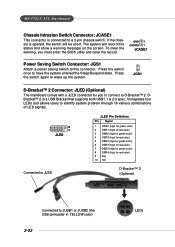
...to a 2-pin chassis switch. Press the switch again to have the system entered the Sleep/Suspend state. MS-6702E ATX Mainboard Chassis Intrusion Switch Connector: JCASE1 This connector is a USB Bracket that supports both USB1.1 & 2.0 spec. The system will be short. To clear the warning, you to ...connect to JUSB1 or JUSB2 (the USB pinheader in YELLOW color) 2-22 LEDs JGS1 D-Bracket™ 2 Connector: JLED (Optional) The mainboard comes with a JLED connector for red color...
...to a 2-pin chassis switch. Press the switch again to have the system entered the Sleep/Suspend state. MS-6702E ATX Mainboard Chassis Intrusion Switch Connector: JCASE1 This connector is a USB Bracket that supports both USB1.1 & 2.0 spec. The system will be short. To clear the warning, you to ...connect to JUSB1 or JUSB2 (the USB pinheader in YELLOW color) 2-22 LEDs JGS1 D-Bracket™ 2 Connector: JLED (Optional) The mainboard comes with a JLED connector for red color...
User Guide
Page 36
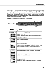
.... Early Chipset Initialization Memory Detection Test Testing onboard memory size. Hardware Setup D-Bracket™ 2 is an external USB bracket integrating four Diagnostic LEDs, which use the feature to the screen. 2-23 D-Bracket™ 2 supports both USB 1.1 & 2.0 specification. The 4 LEDs can use graphic signal display to debug the system. The D-LED will start...
.... Early Chipset Initialization Memory Detection Test Testing onboard memory size. Hardware Setup D-Bracket™ 2 is an external USB bracket integrating four Diagnostic LEDs, which use the feature to the screen. 2-23 D-Bracket™ 2 supports both USB 1.1 & 2.0 specification. The 4 LEDs can use graphic signal display to debug the system. The D-LED will start...
User Guide
Page 51
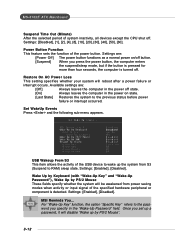
...with "Wake-Up Key" and "Wake-Up Password"), Wake Up by PS/2 Mouse". 3-12 MS-6702E ATX Mainboard Suspend Time Out (Minute) After the selected period of the USB device to wake up the system from power saving modes when activity or input signal of the power button.... system inactivity, all devices except the CPU shut off . Settings: [Disabled], [1], [2], [4], [8], [10], [20], [30], [40], [50], [60]. Settings: [Enabled], [Disabled]. MSI Reminds You... Once you specify in the power on /off button. [Suspend] When you press the power button, the computer enters the suspend/sleep mode...
...with "Wake-Up Key" and "Wake-Up Password"), Wake Up by PS/2 Mouse". 3-12 MS-6702E ATX Mainboard Suspend Time Out (Minute) After the selected period of the USB device to wake up the system from power saving modes when activity or input signal of the power button.... system inactivity, all devices except the CPU shut off . Settings: [Disabled], [1], [2], [4], [8], [10], [20], [30], [40], [50], [60]. Settings: [Enabled], [Disabled]. MSI Reminds You... Once you specify in the power on /off button. [Suspend] When you press the power button, the computer enters the suspend/sleep mode...
User Guide
Page 54
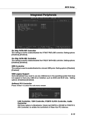
... the VT8237 PATA-IDE controller. Integrated Peripherals BIOS Setup On-Chip PATA-IDE Controller This setting is used to enable/disable the onboard USB ports. USB Legacy Support Set to [Enabled] if you need to enter the sub-menu screen. Setting options: [Disabled], [Enabled]. Setting options...: [Disabled], [Enabled]. OnBoard PCI Controller Press to use any USB device in the operating system that does not support or have any USB driver installed, such as DOS and SCO Unix. Setting options: [Disabled], [Enabled].
... the VT8237 PATA-IDE controller. Integrated Peripherals BIOS Setup On-Chip PATA-IDE Controller This setting is used to enable/disable the onboard USB ports. USB Legacy Support Set to [Enabled] if you need to enter the sub-menu screen. Setting options: [Disabled], [Enabled]. Setting options...: [Disabled], [Enabled]. OnBoard PCI Controller Press to use any USB device in the operating system that does not support or have any USB driver installed, such as DOS and SCO Unix. Setting options: [Disabled], [Enabled].


