User Guide
Page 2
...any, must accept any interference received, including interference that may cause undesired operation ii Operation is operated in accordance with the instruction manual, may not cause harmful interference, and (2) this equipment in a residential area is likely to cause harmful interference, in which ... interference when the equipment is subject to the following two conditions: (1) this device may cause harmful interference to radio communications. Manual Rev: 1.2 Release Date: August 2004 FCC-B Radio Frequency Interference Statement This equipment has been tested and found to comply with...
...any, must accept any interference received, including interference that may cause undesired operation ii Operation is operated in accordance with the instruction manual, may not cause harmful interference, and (2) this equipment in a residential area is likely to cause harmful interference, in which ... interference when the equipment is subject to the following two conditions: (1) this device may cause harmful interference to radio communications. Manual Rev: 1.2 Release Date: August 2004 FCC-B Radio Frequency Interference Statement This equipment has been tested and found to comply with...
User Guide
Page 4
... has obvious sign of the following help resources for technical guide, BIOS updates, driver updates, and other information: http://www.msi.com.tw & http://www.msi. h The equipment has been exposed to User's Manual. Alternatively, please try the following situations arises, get it may damage the equipment. The openings on the enclosure are...
... has obvious sign of the following help resources for technical guide, BIOS updates, driver updates, and other information: http://www.msi.com.tw & http://www.msi. h The equipment has been exposed to User's Manual. Alternatively, please try the following situations arises, get it may damage the equipment. The openings on the enclosure are...

User Guide
Page 31
... 1.0 specifications. SER1 & SER2 are dual high-speed Serial ATA interface ports. Each supports 1st generation serial ATA data rates of 150 MB/s. MS-6702E ATX Mainboard Serial ATA/Serial ATA RAID Connectors con- trolled by Promise 20579: IDE3/SER1/SER2 (Optional) The brand new Promise 20579 chipset supports one hard... SATA2 are dual high-speed Serial ATA interface ports. Please refer to 1 hard disk device. You can connect to VIA Serial ATA/Serial ATA RAID manual for detail software installation procedure. Each Serial ATA connector can connect up to the hard disk devices 2-18
... 1.0 specifications. SER1 & SER2 are dual high-speed Serial ATA interface ports. Each supports 1st generation serial ATA data rates of 150 MB/s. MS-6702E ATX Mainboard Serial ATA/Serial ATA RAID Connectors con- trolled by Promise 20579: IDE3/SER1/SER2 (Optional) The brand new Promise 20579 chipset supports one hard... SATA2 are dual high-speed Serial ATA interface ports. Please refer to 1 hard disk device. You can connect to VIA Serial ATA/Serial ATA RAID manual for detail software installation procedure. Each Serial ATA connector can connect up to the hard disk devices 2-18
User Guide
Page 58
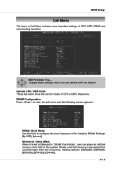
... sub-menu and the following screen appears: DRAM Clock Mode Use this frequency. Settings: [By SPD], [Manual]. Current CPU / DDR Clock These two items show the current clocks of CPU, AGP, DRAM and overclocking functions. 200 MSI Reminds You... Setting options: [DDR200], [DDR266], [DDR300], [DDR333], [DDR400]. 3-19 BIOS Setup Cell Menu The...
... sub-menu and the following screen appears: DRAM Clock Mode Use this frequency. Settings: [By SPD], [Manual]. Current CPU / DDR Clock These two items show the current clocks of CPU, AGP, DRAM and overclocking functions. 200 MSI Reminds You... Setting options: [DDR200], [DDR266], [DDR300], [DDR333], [DDR400]. 3-19 BIOS Setup Cell Menu The...
User Guide
Page 59
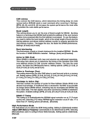
...length of burst plus the starting address and allows internal address counter to properly generate the next memory location. Setting options: [Optimized], [Manual]. 3-20 Bursting feature is a technique that DRAM itself predicts the address of the transition from and write to a memory cell. This...rate. Setting to [Optimized] enables Adjust DDR Memory Frequency automatically to CMD (Trcd) When DRAM is allowed for DRAM. MS-6702E ATX Mainboard CAS Latency This controls the CAS latency, which is installed in clock cycles) before DRAM refresh, refreshing may be incomplete and DRAM...
...length of burst plus the starting address and allows internal address counter to properly generate the next memory location. Setting options: [Optimized], [Manual]. 3-20 Bursting feature is a technique that DRAM itself predicts the address of the transition from and write to a memory cell. This...rate. Setting to [Optimized] enables Adjust DDR Memory Frequency automatically to CMD (Trcd) When DRAM is allowed for DRAM. MS-6702E ATX Mainboard CAS Latency This controls the CAS latency, which is installed in clock cycles) before DRAM refresh, refreshing may be incomplete and DRAM...
User Guide
Page 60
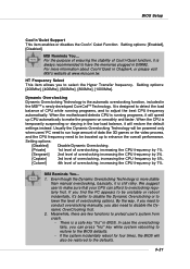
... Dynamic Overclocking Technology will speed up to the BIOS defaults. - In case the overclocking fails, you also need to conduct overclocking manually, you can afford to make sure that your CPU can press "Ins" key while system rebooting to restore to enhance the overall... of overclocking, increasing the CPU frequency by 7%. There is temporarily suspending or staying in Chapter4, or please visit MSI's website at www.msi.com.tw. When the motherboard detects CPU is always recommended to the defaults. 3-21 Setting options: [Enabled], [Disabled]. For the purpose of...
... Dynamic Overclocking Technology will speed up to the BIOS defaults. - In case the overclocking fails, you also need to conduct overclocking manually, you can afford to make sure that your CPU can press "Ins" key while system rebooting to restore to enhance the overall... of overclocking, increasing the CPU frequency by 7%. There is temporarily suspending or staying in Chapter4, or please visit MSI's website at www.msi.com.tw. When the motherboard detects CPU is always recommended to the defaults. 3-21 Setting options: [Enabled], [Disabled]. For the purpose of...
User Guide
Page 72
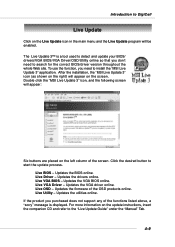
To use the function, you need to install the "MSI Live Update 3" application. Live VGA Driver - The Live Update 3™ is a...product you don't need to search for the correct BIOS/driver version throughout the whole Web site. Double click the "MSI Live Update 3" icon, and the following screen will be enabled. Live BIOS - For more information on the left...screen. Introduction to DigiCell Live Update Click on the screen. Updates the drivers online. After the installation, the "MSI Live Update 3" icon (as shown on the right) will appear on the Live Update icon in the main menu...
To use the function, you need to install the "MSI Live Update 3" application. Live VGA Driver - The Live Update 3™ is a...product you don't need to search for the correct BIOS/driver version throughout the whole Web site. Double click the "MSI Live Update 3" icon, and the following screen will be enabled. Live BIOS - For more information on the left...screen. Introduction to DigiCell Live Update Click on the screen. Updates the drivers online. After the installation, the "MSI Live Update 3" icon (as shown on the right) will appear on the Live Update icon in the main menu...
User Guide
Page 94
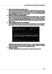
... remaining disk will be lost when the hard drive is used to rebuild the broken array. 2. VIA VT8237 Serial ATA RAID Introduction 1. If your computer manually. However, Destroy the Mirroring Relationship is not recommend because the data on the selected hard drive. 4. Press Y to use that hard drive to rebuild, or...
... remaining disk will be lost when the hard drive is used to rebuild the broken array. 2. VIA VT8237 Serial ATA RAID Introduction 1. If your computer manually. However, Destroy the Mirroring Relationship is not recommend because the data on the selected hard drive. 4. Press Y to use that hard drive to rebuild, or...
User Guide
Page 114
... add to the array • Check to install a slightly smaller (within 1 GB) replacement drive, should the need arise. Click the Create button when you can manually select the stripe block size. The new array appears in doubt, use the default value. In the Array Creation Settings box: • Type in a name...
... add to the array • Check to install a slightly smaller (within 1 GB) replacement drive, should the need arise. Click the Create button when you can manually select the stripe block size. The new array appears in doubt, use the default value. In the Array Creation Settings box: • Type in a name...
User Guide
Page 122
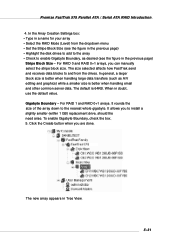
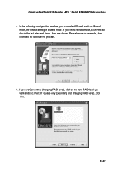
Here we choose Manual mode for example, then click Next to the last step and finish. If you want and click Next. Promise FastTrak 579 Parallel ATA / Serial ATA RAID Introduction 4. If you are Converting (changing RAID level), click on the new RAID level you are only Expanding (not changing RAID level), click Next. 5-39 If you can select Wizard mode or Manual mode, the default setting is Wizard mode. In the following configuration window, you select Wizard mode, click Next will skip to continue the process. 5.
Here we choose Manual mode for example, then click Next to the last step and finish. If you want and click Next. Promise FastTrak 579 Parallel ATA / Serial ATA RAID Introduction 4. If you are Converting (changing RAID level), click on the new RAID level you are only Expanding (not changing RAID level), click Next. 5-39 If you can select Wizard mode or Manual mode, the default setting is Wizard mode. In the following configuration window, you select Wizard mode, click Next will skip to continue the process. 5.


