
User Guide
Page 2
This equipment generates, uses and can radiate radio frequency energy and, if not installed and used in order to comply with the emission limits. Notice 2 Shielded interface cables and A.C. Notice 1 The changes or modifications not expressly approved by the party responsible for a class B digital device, pursuant to part 15 of this equipment in a residential area is operated in accordance with the instruction manual, may cause harmful interference to radio communications. power cord, if any, must be required to correct the interference at his own expense. Micro-Star ...
This equipment generates, uses and can radiate radio frequency energy and, if not installed and used in order to comply with the emission limits. Notice 2 Shielded interface cables and A.C. Notice 1 The changes or modifications not expressly approved by the party responsible for a class B digital device, pursuant to part 15 of this equipment in a residential area is operated in accordance with the instruction manual, may cause harmful interference to radio communications. power cord, if any, must be required to correct the interference at his own expense. Micro-Star ...
User Guide
Page 3
... try the following help resources for FAQ, technical guide, BIOS updates, driver updates, and other information: http://www.msi.com.tw/ Contact our technical staff at: support@msi.com.tw iii Visit the MSI website for further guidance. Trademarks All trademarks are registered trademarks of International Business Machines Corporation. Award® is the...
... try the following help resources for FAQ, technical guide, BIOS updates, driver updates, and other information: http://www.msi.com.tw/ Contact our technical staff at: support@msi.com.tw iii Visit the MSI website for further guidance. Trademarks All trademarks are registered trademarks of International Business Machines Corporation. Award® is the...
User Guide
Page 4
Lay this User's Manual for air convection hence protects the equipment from humidity. 4. Do not place anything over the power cord. 8. If any liquid into the equipment. z Liquid has penetrated into the opening that people can not get the equipment checked by the manufacturer. z The equipment has dropped and damaged. Never pour any of explosion if battery is damaged. z The equipment has been exposed to the power inlet. 7. z The equipment has obvious sign of the power source and adjust properly 110/220V before inserting any add-on it up. 5. Safety Instructions ...
Lay this User's Manual for air convection hence protects the equipment from humidity. 4. Do not place anything over the power cord. 8. If any liquid into the equipment. z Liquid has penetrated into the opening that people can not get the equipment checked by the manufacturer. z The equipment has dropped and damaged. Never pour any of explosion if battery is damaged. z The equipment has been exposed to the power inlet. 7. z The equipment has obvious sign of the power source and adjust properly 110/220V before inserting any add-on it up. 5. Safety Instructions ...
User Guide
Page 5
Getting Started 1-1 Mainboard Specifications 1-2 Mainboard Layout 1-4 MSI Special Features 1-5 Fuzzy Logic™ 4 1-5 Live BIOS™/Live Driver 1-7 Live Monitor 1-7 D-Bracket™ 2 (Optional 1-8 PC Alert™ 4 1-10 Chapter 2. Hardware Setup 2-1 Quick Components Guide 2-2 ...
Getting Started 1-1 Mainboard Specifications 1-2 Mainboard Layout 1-4 MSI Special Features 1-5 Fuzzy Logic™ 4 1-5 Live BIOS™/Live Driver 1-7 Live Monitor 1-7 D-Bracket™ 2 (Optional 1-8 PC Alert™ 4 1-10 Chapter 2. Hardware Setup 2-1 Quick Components Guide 2-2 ...
User Guide
Page 6
D-Bracket™ 2 Connector: JLED 2-13 Jumpers 2-14 Clear CMOS Jumper: JBAT1 2-14 FSB Clock Jumper: SW3 2-14 Slots 2-15 PCI Interrupt Request Routing 2-15 Chapter 3. or 6-Channel Audio Function A-2 Installing the Audio Driver A-2 Using 4- or 6-Channel Audio Function A-2 Testing the Connected Speakers A-6 Testing Each Speaker A-6 Playing KaraOK A-8 Playing KaraOK A-8 vi BIOS Setup 3-1 Entering Setup 3-2 Selecting the First Boot Device 3-2 Control Keys 3-3 Getting Help 3-3 The Main Menu 3-4 Standard CMOS Features 3-6 Advanced BIOS Features 3-7 Advanced Chipset ...
D-Bracket™ 2 Connector: JLED 2-13 Jumpers 2-14 Clear CMOS Jumper: JBAT1 2-14 FSB Clock Jumper: SW3 2-14 Slots 2-15 PCI Interrupt Request Routing 2-15 Chapter 3. or 6-Channel Audio Function A-2 Installing the Audio Driver A-2 Using 4- or 6-Channel Audio Function A-2 Testing the Connected Speakers A-6 Testing Each Speaker A-6 Playing KaraOK A-8 Playing KaraOK A-8 vi BIOS Setup 3-1 Entering Setup 3-2 Selecting the First Boot Device 3-2 Control Keys 3-3 Getting Help 3-3 The Main Menu 3-4 Standard CMOS Features 3-6 Advanced BIOS Features 3-7 Advanced Chipset ...

User Guide
Page 7
Getting Started Getting Started Thank you for optimal system efficiency. Designed to fit the advanced AMD® Athlon™, Athlon™ XP or Duron™ processors, the K7T266 Pro2-U/UL deliver a high performance and professional desktop platform solution. 1-1 The K7T266 Pro2-U/UL are based on VIA® Apollo KT266A & VT8235 chipsets for purchasing the K7T266 Pro2-U/UL (MS6593 v1.X) ATX mainboard. Getting Started Chapter 1.
Getting Started Getting Started Thank you for optimal system efficiency. Designed to fit the advanced AMD® Athlon™, Athlon™ XP or Duron™ processors, the K7T266 Pro2-U/UL deliver a high performance and professional desktop platform solution. 1-1 The K7T266 Pro2-U/UL are based on VIA® Apollo KT266A & VT8235 chipsets for purchasing the K7T266 Pro2-U/UL (MS6593 v1.X) ATX mainboard. Getting Started Chapter 1.

User Guide
Page 8
Integrated Direct Sound AC97 audio. - h Six 32-bit PCI bus slots (support 3.3v/5v PCI bus interface). ACPI & PC2001 compliant enhanced power management. - Slots h One AGP (Accelerated Graphics Port) slot. - Chipset h VIA® KT266A chipset - Dual channel Ultra DMA 33/66/100/133 master mode EIDE controller. - Integrated USB 2.0 controller. - Supports AGP 2.0 1x/2x/4x. On-Board Peripherals h On-Board Peripherals include: - 1 floppy port supports 2 FDDs with PIO, Bus Master and Ultra DMA133/100/66/33 operation modes. h Supports up to 2GB PC2100/1600 DDR SDRAMs. h Supports 2....
Integrated Direct Sound AC97 audio. - h Six 32-bit PCI bus slots (support 3.3v/5v PCI bus interface). ACPI & PC2001 compliant enhanced power management. - Slots h One AGP (Accelerated Graphics Port) slot. - Chipset h VIA® KT266A chipset - Dual channel Ultra DMA 33/66/100/133 master mode EIDE controller. - Integrated USB 2.0 controller. - Supports AGP 2.0 1x/2x/4x. On-Board Peripherals h On-Board Peripherals include: - 1 floppy port supports 2 FDDs with PIO, Bus Master and Ultra DMA133/100/66/33 operation modes. h Supports up to 2GB PC2100/1600 DDR SDRAMs. h Supports 2....

User Guide
Page 9
LAN (Optional) h 10/100Mbps Ethernet onboard. Dimension h ATX Form Factor: 30.5 cm (L) x 20 cm (W). h Voltage independent adjustment in CPU, DDR, AGP. 1-3 Getting Started - 2 serial ports (COM A + COM B) - 1 parallel port supports SPP/EPP/ECP mode - 1 audio/game port - 6 USB 2.0 ports (Rear * 2/ Front * 4) Audio h RealTek ALC650 6-channel audio. Others h Suspend to RAM/Disk (S3/S4). BIOS h The mainboard BIOS provides "Plug & Play" BIOS which records your mainboard specifications. h PC2001 compliant. Mounting h 6 mounting holes. h The mainboard provides a Desktop Management ...
LAN (Optional) h 10/100Mbps Ethernet onboard. Dimension h ATX Form Factor: 30.5 cm (L) x 20 cm (W). h Voltage independent adjustment in CPU, DDR, AGP. 1-3 Getting Started - 2 serial ports (COM A + COM B) - 1 parallel port supports SPP/EPP/ECP mode - 1 audio/game port - 6 USB 2.0 ports (Rear * 2/ Front * 4) Audio h RealTek ALC650 6-channel audio. Others h Suspend to RAM/Disk (S3/S4). BIOS h The mainboard BIOS provides "Plug & Play" BIOS which records your mainboard specifications. h PC2001 compliant. Mounting h 6 mounting holes. h The mainboard provides a Desktop Management ...

User Guide
Page 10
MS-6593 ATX Mainboard Mainboard Layout Top: Mouse Bottom: Keyboard T: LAN Jack (Optional) B: USB Ports SOCKET 462 CFAN1 Top: Parallel Port Bottom: COM A COM B AT X Power Supply DDR 1 DDR 2 FDD 1 Top: Game Port Bottom: Line-Out Line-In Mic J10 J3 BIOS VIA KT266A JPW1 AGP Slot PCI Slot 1 Winbond W83697HF PCI Slot 2 PCI Slot 3 Re al Te k ALC650 PCI Slot 4 SFAN1 SW3 VT8235 BATT + J B AT 1 PCI Slot 5 PCI Slot 6 JLED IDE 1 IDE 2 JAUD1 JUSB2 JUSB3 JFP1 JFP2 K7T266 Pro2-U/UL (MS-6593 v1.X) ATX Mainboard 1-4
MS-6593 ATX Mainboard Mainboard Layout Top: Mouse Bottom: Keyboard T: LAN Jack (Optional) B: USB Ports SOCKET 462 CFAN1 Top: Parallel Port Bottom: COM A COM B AT X Power Supply DDR 1 DDR 2 FDD 1 Top: Game Port Bottom: Line-Out Line-In Mic J10 J3 BIOS VIA KT266A JPW1 AGP Slot PCI Slot 1 Winbond W83697HF PCI Slot 2 PCI Slot 3 Re al Te k ALC650 PCI Slot 4 SFAN1 SW3 VT8235 BATT + J B AT 1 PCI Slot 5 PCI Slot 6 JLED IDE 1 IDE 2 JAUD1 JUSB2 JUSB3 JFP1 JFP2 K7T266 Pro2-U/UL (MS-6593 v1.X) ATX Mainboard 1-4

User Guide
Page 11
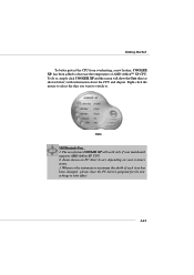
... Apply to apply the new setup value. After rebooting, click Turbo to view and adjust the current system status. Features: Ø MSI Logo links to the MSI Web site Ø CPU Speed allows users to adjust the CPU speed through CPU Multiplier and FSB Ø Voltage allows user to .... The CPU FSB will automatically increase the testing value until the PC reboots. Click Default to adjust the voltage of CPU/Memory/AGP Ø MSI Info provides information about the mainboard, BIOS and OS Ø CPU Info provides detailed information about the CPU Ø CPU Fan Speed shows the...
... Apply to apply the new setup value. After rebooting, click Turbo to view and adjust the current system status. Features: Ø MSI Logo links to the MSI Web site Ø CPU Speed allows users to adjust the CPU speed through CPU Multiplier and FSB Ø Voltage allows user to .... The CPU FSB will automatically increase the testing value until the PC reboots. Click Default to adjust the voltage of CPU/Memory/AGP Ø MSI Info provides information about the mainboard, BIOS and OS Ø CPU Info provides detailed information about the CPU Ø CPU Fan Speed shows the...
User Guide
Page 12
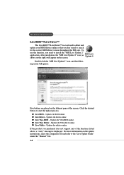
... listed above, a "sorry" message is a tool used to detect and update your BIOS/drivers online so that you need to install the "MSI Live Update 2" application. To use the function, you don't need to search for the correct BIOS/driver version throughout the Web site. z ...BIOS - Updates the drivers online. z Live VGA Driver - Updates the VGA driver online. Updates the utilities online. z Live Utility - After installation, the "MSI Live Update 2" icon (as shown on the right) will appear: Five buttons are placed on the update instructions, insert the companion CD and refer to...
... listed above, a "sorry" message is a tool used to detect and update your BIOS/drivers online so that you need to install the "MSI Live Update 2" application. To use the function, you don't need to search for the correct BIOS/driver version throughout the Web site. z ...BIOS - Updates the drivers online. z Live VGA Driver - Updates the VGA driver online. Updates the utilities online. z Live Utility - After installation, the "MSI Live Update 2" icon (as shown on the right) will appear: Five buttons are placed on the update instructions, insert the companion CD and refer to...
User Guide
Page 13
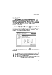
...Update 2" application. z Preference - Exits the Live Monitor™ application. Provides a link to a database which contents various possible questions about MSI's products for users to run the application. Double click this icon to inquire. 1-7 You can specify how often the system will automatically search ...8482; is any. Configures the Search function, including the Search schedule. Searches for the BIOS/drivers version you need immediately. Double click the "MSI Live Monitor" icon at the lower-right corner of the taskbar, and the following dialog box will appear on the...
...Update 2" application. z Preference - Exits the Live Monitor™ application. Provides a link to a database which contents various possible questions about MSI's products for users to run the application. Double click this icon to inquire. 1-7 You can specify how often the system will automatically search ...8482; is any. Configures the Search function, including the Search schedule. Searches for the BIOS/drivers version you need immediately. Double click the "MSI Live Monitor" icon at the lower-right corner of the taskbar, and the following dialog box will appear on the...

User Guide
Page 14
Early Chipset Initialization Memory Detection Test - Initializing Keyboard Controller. Testing VGA BIOS - These users can debug all problems that fail the system, such as VGA, RAM or other failures. Testing onboard memory size. D-Bracket™ 2 supports both USB 1.1 & 2.0 spec. The D-LED will hang if the memory module is damaged or 3 4 not installed properly. The 4 LEDs can use graphic signal display to help users understand their system. This will hang here if the processor is damaged or not installed properly. MS-6593 ATX Mainboard D-Bracket™ 2 (Optional...
Early Chipset Initialization Memory Detection Test - Initializing Keyboard Controller. Testing VGA BIOS - These users can debug all problems that fail the system, such as VGA, RAM or other failures. Testing onboard memory size. D-Bracket™ 2 supports both USB 1.1 & 2.0 spec. The D-LED will hang if the memory module is damaged or 3 4 not installed properly. The 4 LEDs can use graphic signal display to help users understand their system. This will hang here if the processor is damaged or not installed properly. MS-6593 ATX Mainboard D-Bracket™ 2 (Optional...

User Guide
Page 15
Testing base memory from 240K to all ISA. Initializing Floppy Drive Controller - This will initializing Floppy Drive and controller. Assign Resources to 640K and extended memory above 1MB using various patterns. This will start detecting CPU clock, checking type of video onboard. Boot Attempt - This will show information regarding the processor (like 3 4 brand name, system bus, etc...) Testing RTC (Real Time Clock) Initializing Video Interface - Getting Started D-BracketTM2 Description Processor Initialization 1 2 - BIOS Sign On - This will set low stack ...
Testing base memory from 240K to all ISA. Initializing Floppy Drive Controller - This will initializing Floppy Drive and controller. Assign Resources to 640K and extended memory above 1MB using various patterns. This will start detecting CPU clock, checking type of video onboard. Boot Attempt - This will show information regarding the processor (like 3 4 brand name, system bus, etc...) Testing RTC (Real Time Clock) Initializing Video Interface - Getting Started D-BracketTM2 Description Processor Initialization 1 2 - BIOS Sign On - This will set low stack ...

User Guide
Page 16
The PC Alert™ 4 icon on the screen, with the abnormal item highlighted in the CD-ROM disk. Adjusting Keys Temperature Modes COOLER XP Users can find in red. The utility is just like your PC doctor that can detect the following PC hardware status during real time operation: Ø monitor CPU & system temperatures Ø monitor fan speeds Ø monitor system voltages If one of the items above is a utility you can use the Adjusting Keys to change the minimum and maximum threshold of either Fahrenheit ( ) or Celsius ( ). This will continue to be immediately shown on ...
The PC Alert™ 4 icon on the screen, with the abnormal item highlighted in the CD-ROM disk. Adjusting Keys Temperature Modes COOLER XP Users can find in red. The utility is just like your PC doctor that can detect the following PC hardware status during real time operation: Ø monitor CPU & system temperatures Ø monitor fan speeds Ø monitor system voltages If one of the items above is a utility you can use the Adjusting Keys to change the minimum and maximum threshold of either Fahrenheit ( ) or Celsius ( ). This will continue to be immediately shown on ...
User Guide
Page 17
To do so, simply click COOLER XP and the screen will work only if your system's status. 3. Cute MSI Reminds You... 1. Items shown on PC Alert 4 vary depending on your mainboard supports AMD Athlon XP CPU. 2. Whenever the minimum or maximum threshold of each ...
To do so, simply click COOLER XP and the screen will work only if your system's status. 3. Cute MSI Reminds You... 1. Items shown on PC Alert 4 vary depending on your mainboard supports AMD Athlon XP CPU. 2. Whenever the minimum or maximum threshold of each ...

User Guide
Page 18
Hardware Setup Chapter 2. While doing the installation, be careful in holding the components and follow the installation procedures. 2-1 Also, it provides the instructions on the mainboard. Hardware Setup Hardware Setup This chapter tells you how to install the CPU, memory modules, and expansion cards, as well as how to setup the jumpers on connecting the peripheral devices, such the mouse, keyboard, etc.
Hardware Setup Chapter 2. While doing the installation, be careful in holding the components and follow the installation procedures. 2-1 Also, it provides the instructions on the mainboard. Hardware Setup Hardware Setup This chapter tells you how to install the CPU, memory modules, and expansion cards, as well as how to setup the jumpers on connecting the peripheral devices, such the mouse, keyboard, etc.
User Guide
Page 20
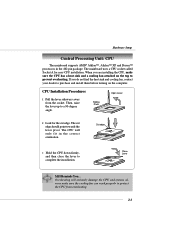
... pivot. The cut edge. If you are installing the CPU, make sure the cooling fan can work properly to prevent overheating. Sliding Plate Open Lever 2. MSI Reminds You... CPU Installation Procedures 1. Look for easy CPU installation. Hardware Setup Central Processing Unit: CPU The mainboard supports AMD® Athlon™, Athlon™...
... pivot. The cut edge. If you are installing the CPU, make sure the cooling fan can work properly to prevent overheating. Sliding Plate Open Lever 2. MSI Reminds You... CPU Installation Procedures 1. Look for easy CPU installation. Hardware Setup Central Processing Unit: CPU The mainboard supports AMD® Athlon™, Athlon™...

User Guide
Page 21
...always turn off the ATX power supply or unplug the power supply's power cord from grounded outlet first to improve heat dissipation. Overclocking This motherboard is not recommended. If you want to get more information on the proper cooling, you can visit AMD's website for CPU AMD Athlon... abnormal setting, while doing overclocking. You also need to add thermal grease between the CPU and heatsink to ensure the safety of CPU. MSI Reminds You... These are securely fastened and in good contact with each other. MS-6593 ATX Mainboard WARNING! Thermal Issue for reference. Then...
...always turn off the ATX power supply or unplug the power supply's power cord from grounded outlet first to improve heat dissipation. Overclocking This motherboard is not recommended. If you want to get more information on the proper cooling, you can visit AMD's website for CPU AMD Athlon... abnormal setting, while doing overclocking. You also need to add thermal grease between the CPU and heatsink to ensure the safety of CPU. MSI Reminds You... These are securely fastened and in good contact with each other. MS-6593 ATX Mainboard WARNING! Thermal Issue for reference. Then...

User Guide
Page 22
You can install PC2100/DDR266 or PC1600/DDR200 modules on the center of the DIMM slot will only fit in the socket. 3. The module will automatically close. The DDR DIMM has only one notch on the DDR DIMM slots (DDR 1~2). Volt Notch 2-5 The plastic clip at each side of module. Insert the DIMM memory module vertically into the DIMM slot. Hardware Setup Memory The mainboard provides 2 slots for 184-pin DDR SDRAM DIMM (Double In-Line Memory Module) modules and supports the memory size up to 2GB. DDR DIMM Slots (DDR 1~2) Installing DDR Modules 1. Then push it in until the ...
You can install PC2100/DDR266 or PC1600/DDR200 modules on the center of the DIMM slot will only fit in the socket. 3. The module will automatically close. The DDR DIMM has only one notch on the DDR DIMM slots (DDR 1~2). Volt Notch 2-5 The plastic clip at each side of module. Insert the DIMM memory module vertically into the DIMM slot. Hardware Setup Memory The mainboard provides 2 slots for 184-pin DDR SDRAM DIMM (Double In-Line Memory Module) modules and supports the memory size up to 2GB. DDR DIMM Slots (DDR 1~2) Installing DDR Modules 1. Then push it in until the ...