
User Guide
Page 4
...or plug is within its safety range and has been adjusted properly to the value of 110/220V before connecting the equipment to User's Guide z the equipment was dropped and damaged z the equipment has obvious signs of breakage 12. Note: Do not cover the openings. 6....Place the power cord in an unconditioned environment with a storage temperature of battery recommended by improper battery replacement, use later. 3. Lay this User's Guide for air convection and to step on card or module. 9. Read the safety instructions carefully. 2. Make sure that people are used for possible...
...or plug is within its safety range and has been adjusted properly to the value of 110/220V before connecting the equipment to User's Guide z the equipment was dropped and damaged z the equipment has obvious signs of breakage 12. Note: Do not cover the openings. 6....Place the power cord in an unconditioned environment with a storage temperature of battery recommended by improper battery replacement, use later. 3. Lay this User's Guide for air convection and to step on card or module. 9. Read the safety instructions carefully. 2. Make sure that people are used for possible...
User Guide
Page 5
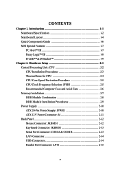
Introduction 1-1 Mainboard Specification 1-2 Mainboard Layout 1-4 Quick Components Guide 1-6 MSI Special Features 1-7 PC Alert™ III 1-7 Fuzzy Logic™ III 1-8 D-LED™&D-Bracket 1-9 Chapter 2. Hardware Setup 2-1 Central Processing ... 2-5 Recommended Computer Case and Axial Fans 2-6 Memory Installation 2-7 DDR Module Combination 2-8 DDR Module Installation Procedures 2-9 Power Supply 2-10 ATX 20-Pin Power Supply: JPWR1 2-10 ATX 12V Power Connector: J4 2-11 Back Panel 2-12 Mouse Connector: JKBMS1 2-12 Keyboard Connector: JKBMS1 2-13 Serial Port Connector: COM...
Introduction 1-1 Mainboard Specification 1-2 Mainboard Layout 1-4 Quick Components Guide 1-6 MSI Special Features 1-7 PC Alert™ III 1-7 Fuzzy Logic™ III 1-8 D-LED™&D-Bracket 1-9 Chapter 2. Hardware Setup 2-1 Central Processing ... 2-5 Recommended Computer Case and Axial Fans 2-6 Memory Installation 2-7 DDR Module Combination 2-8 DDR Module Installation Procedures 2-9 Power Supply 2-10 ATX 20-Pin Power Supply: JPWR1 2-10 ATX 12V Power Connector: J4 2-11 Back Panel 2-12 Mouse Connector: JKBMS1 2-12 Keyboard Connector: JKBMS1 2-13 Serial Port Connector: COM...

User Guide
Page 8
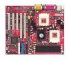
TOPICS Mainboard Specification 1-2 Mainboard Layout 1-4 Quick Components Guide 1-6 MSI Special Features 1-7 1-1 The MS-6501 V1.X ATX mainboard is an excellent computer mainboard based on the innovative AMD-762™ & 768™ chipsets, which supports the dual AMD Athlon™ MP processors series and provides you for your needs. Chapter 1. Getting Started Getting Started Getting Started 1 Thank you a cost-effective solution to meet your purchase of the MSI mainboard.
TOPICS Mainboard Specification 1-2 Mainboard Layout 1-4 Quick Components Guide 1-6 MSI Special Features 1-7 1-1 The MS-6501 V1.X ATX mainboard is an excellent computer mainboard based on the innovative AMD-762™ & 768™ chipsets, which supports the dual AMD Athlon™ MP processors series and provides you for your needs. Chapter 1. Getting Started Getting Started Getting Started 1 Thank you a cost-effective solution to meet your purchase of the MSI mainboard.
User Guide
Page 13
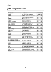
... Components Guide Component JFSB1 JPWR1 J4 JKBMS1 JKBMS1 COM A & COM B USB Connectors LAN Connector LPT1 FDD1 IDE1~ IDE2 JFP1/JFP2 JCD1 JAUX1 JPHN1 JWR1 JWL1 CPUFAN1/CPUFAN2/ SYSFAN/PSFAN1/NBFAN1 JUSB1 JDB1 JIR1 JCI1 JBAT1 AGP Pro Slot PCI Slots Function For CPU Clock Frequency ATX 20-pin power connector ATX 12V power...
... Components Guide Component JFSB1 JPWR1 J4 JKBMS1 JKBMS1 COM A & COM B USB Connectors LAN Connector LPT1 FDD1 IDE1~ IDE2 JFP1/JFP2 JCD1 JAUX1 JPHN1 JWR1 JWL1 CPUFAN1/CPUFAN2/ SYSFAN/PSFAN1/NBFAN1 JUSB1 JDB1 JIR1 JCI1 JBAT1 AGP Pro Slot PCI Slots Function For CPU Clock Frequency ATX 20-pin power connector ATX 12V power...

User Guide
Page 36
... panel connectors JFP1 and JFP2 allow you to connect to GND Reserved. Both JFP1 and JFP2 are compliant with Intel® Front Panel I/O Connectivity Design Guide.
... panel connectors JFP1 and JFP2 allow you to connect to GND Reserved. Both JFP1 and JFP2 are compliant with Intel® Front Panel I/O Connectivity Design Guide.

User Guide
Page 38
The connector will power up the system when a signal is compliant with Intel® Front Panel I /O Connectivity Design Guide. 1 NC GND WOR (wake-up the computer via remote control through the modem card. JWL1 is received through a local area network. You can wake up ...on LAN) JWL1 2-21 JWR1 is compliant with Intel® Front Panel I /O Connectivity Design Guide. 5VSB 1 GND WOL (wake-up on ring) NC 5VSB JWR1 Wake On LAN Connector: JWL1 This connector allows you to connect to a LAN card with...
The connector will power up the system when a signal is compliant with Intel® Front Panel I /O Connectivity Design Guide. 1 NC GND WOR (wake-up the computer via remote control through the modem card. JWL1 is received through a local area network. You can wake up ...on LAN) JWL1 2-21 JWR1 is compliant with Intel® Front Panel I /O Connectivity Design Guide. 5VSB 1 GND WOL (wake-up on ring) NC 5VSB JWR1 Wake On LAN Connector: JWL1 This connector allows you to connect to a LAN card with...

User Guide
Page 40
JUSB1 is compliant with Intel® Front Panel I/O Connectivity Design Guide. 2 10 1 9 JUSB1 JUSB1 Pin Definition Pin Description Pin Description 1 USBPWR 6 USBP1+ 2 USBPWR 7 GND 3 USBP0- 8 GND 4 USBP1- 9 NC 5 USBP0+ 10 USBOC- 2-23 Hardware Setup USB Front Panel Connector: JUSB1 The mainboard provides a Universal Serial Bus (USB) pin header that allows you to connect an optional USB port for front panel.
JUSB1 is compliant with Intel® Front Panel I/O Connectivity Design Guide. 2 10 1 9 JUSB1 JUSB1 Pin Definition Pin Description Pin Description 1 USBPWR 6 USBP1+ 2 USBPWR 7 GND 3 USBP0- 8 GND 4 USBP1- 9 NC 5 USBP0+ 10 USBOC- 2-23 Hardware Setup USB Front Panel Connector: JUSB1 The mainboard provides a Universal Serial Bus (USB) pin header that allows you to connect an optional USB port for front panel.

User Guide
Page 42
Hardware Setup IrDA Infrared Module Connector: JIR1 This connector allows you to use the IR function. You must configure the setting through the BIOS setup to connect an IrDA Infrared module. JIR1 is compliant with Intel® Front Panel I/O Connectivity Design Guide. 26 15 JIR1 Pin Definition Pin Signal Description Pin Signal Description 1 NC Not Assigned 2 (No pin) Key 3 +5V IR Power 4 GND Ground 5 IRTX IrDA serial output 6 IRRX IrDA serial input 2-25
Hardware Setup IrDA Infrared Module Connector: JIR1 This connector allows you to use the IR function. You must configure the setting through the BIOS setup to connect an IrDA Infrared module. JIR1 is compliant with Intel® Front Panel I/O Connectivity Design Guide. 26 15 JIR1 Pin Definition Pin Signal Description Pin Signal Description 1 NC Not Assigned 2 (No pin) Key 3 +5V IR Power 4 GND Ground 5 IRTX IrDA serial output 6 IRRX IrDA serial input 2-25

User Guide
Page 43
JCI1 is connected to a 2-pin chassis switch. To clear the warning, you must enter the BIOS utility and clear the record. The system will be short. Chapter 2 Chassis Intrusion Switch Connector: JCI1 This connector is compliant with Intel® Front Panel I/O Connectivity Design Guide. 2 GND 1 CINTRU JCI1 2-26 If the chassis is opened, the switch will record this status and show a warning message on the screen.
JCI1 is connected to a 2-pin chassis switch. To clear the warning, you must enter the BIOS utility and clear the record. The system will be short. Chapter 2 Chassis Intrusion Switch Connector: JCI1 This connector is compliant with Intel® Front Panel I/O Connectivity Design Guide. 2 GND 1 CINTRU JCI1 2-26 If the chassis is opened, the switch will record this status and show a warning message on the screen.
User Guide
Page 44
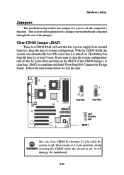
...1 3 Clear Data 1 VBAT RTCRST# GND JBAT1 You can automatically boot OS every time it will explain how to change your motherboard's function through the use the JBAT1 (Clear CMOS Jumper ) to clear data. Then return to clear the system configuration, turn off.... Avoid WARNING! it is off the AC power first and then use of system configuration. Hardware Setup Jumpers The motherboard provides one jumper for at least 5 years. Clear CMOS Jumper: JBAT1 There is on board that has a power ... of the jumper. JBAT1 is compliant with Intel® Front Panel I/O Connectivity Design Guide.
...1 3 Clear Data 1 VBAT RTCRST# GND JBAT1 You can automatically boot OS every time it will explain how to change your motherboard's function through the use the JBAT1 (Clear CMOS Jumper ) to clear data. Then return to clear the system configuration, turn off.... Avoid WARNING! it is off the AC power first and then use of system configuration. Hardware Setup Jumpers The motherboard provides one jumper for at least 5 years. Clear CMOS Jumper: JBAT1 There is on board that has a power ... of the jumper. JBAT1 is compliant with Intel® Front Panel I/O Connectivity Design Guide.
