User Guide
Page 11
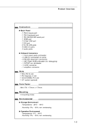
...condensing 1-3 Temperature: 0oC ~ 60oC - Mini ITX: 170mm x 170mm Mounting - 4 mounting holes Environmental Storage Environment - Humidity: 5% ~ 90% non condensing Operation Environment - Product Overview Connectors Back Panel - 1 PS/2 mouse port - 1 PS/2 keyboard port - 1 RS-232/422/485 serial port - 1 HDMI port - 1... panel audio pinheader - 2 USB 2.0 pinheaders (4 ports) - 4 RS-232 serial port connectors - 1 SPI Flash ROM pinheader (for debugging) - 1 S/PDIF-out pinheader - 1 LVDS connector - 1 amplifier connector Slots - 1 Mini PCI-E slot - 1 PCI Express x1 slot - 1 32-bit/33MHz PCI slot...
...condensing 1-3 Temperature: 0oC ~ 60oC - Mini ITX: 170mm x 170mm Mounting - 4 mounting holes Environmental Storage Environment - Humidity: 5% ~ 90% non condensing Operation Environment - Product Overview Connectors Back Panel - 1 PS/2 mouse port - 1 PS/2 keyboard port - 1 RS-232/422/485 serial port - 1 HDMI port - 1... panel audio pinheader - 2 USB 2.0 pinheaders (4 ports) - 4 RS-232 serial port connectors - 1 SPI Flash ROM pinheader (for debugging) - 1 S/PDIF-out pinheader - 1 LVDS connector - 1 amplifier connector Slots - 1 Mini PCI-E slot - 1 PCI Express x1 slot - 1 32-bit/33MHz PCI slot...
User Guide
Page 13
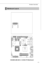
Mainboard Layout Product Overview CF1 PCI_ E1 COM2 COM4 COM3 COM5 PCI1 JFP1 JUSB1 JUSB2 SATA2 SATA1 SATA4 SATA3 JSPD1 Intel ICH9M-E JAU D1 Audio JAMP1 T: Line-In M: Line-Out B: Mic-In Top: LAN1 Jack LAN Bottom: USB Ports CON1 IDE 1 JMB368 JSPI 1 LAN Top: LAN2 Jack J2 Bottom: USB Ports JLVDS1 Intel GM45 To p: VGA Port Bot to m: DVI Port SY S FA N 1 ATX1 DIMM1 DIMM2 To p: Serial Port Bot to m: HDMI Port Top: Mouse J1 Bottom: Keybo ard C P UF AN 1 IM-GM45 (MS-9818 v1.X) Mini ITX Mainboard 1-5
Mainboard Layout Product Overview CF1 PCI_ E1 COM2 COM4 COM3 COM5 PCI1 JFP1 JUSB1 JUSB2 SATA2 SATA1 SATA4 SATA3 JSPD1 Intel ICH9M-E JAU D1 Audio JAMP1 T: Line-In M: Line-Out B: Mic-In Top: LAN1 Jack LAN Bottom: USB Ports CON1 IDE 1 JMB368 JSPI 1 LAN Top: LAN2 Jack J2 Bottom: USB Ports JLVDS1 Intel GM45 To p: VGA Port Bot to m: DVI Port SY S FA N 1 ATX1 DIMM1 DIMM2 To p: Serial Port Bot to m: HDMI Port Top: Mouse J1 Bottom: Keybo ard C P UF AN 1 IM-GM45 (MS-9818 v1.X) Mini ITX Mainboard 1-5

User Guide
Page 25
Serial Port The serial port is a 16550A high speed communications port that the other end of transmitting uncompressed streams. HDMI ..., simply plug your monitor manual for more information.) USB Port The USB (Universal Serial Bus) port is for a PS/2® mouse/keyboard. You can attach a serial mouse or other serial devices directly to connect an LCD monitor. Hardware Setup Back Panel RS-232/422/...485 M ou se Serial Port VGA Port LAN LAN Line-In Line-Out Keyboard HDMI Port DVI Port USB Ports USB Ports...
Serial Port The serial port is a 16550A high speed communications port that the other end of transmitting uncompressed streams. HDMI ..., simply plug your monitor manual for more information.) USB Port The USB (Universal Serial Bus) port is for a PS/2® mouse/keyboard. You can attach a serial mouse or other serial devices directly to connect an LCD monitor. Hardware Setup Back Panel RS-232/422/...485 M ou se Serial Port VGA Port LAN LAN Line-In Line-Out Keyboard HDMI Port DVI Port USB Ports USB Ports...
User Guide
Page 28
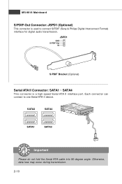
JSPD1 GND S/PDIF-Out 5V S/PDIF Bracket (Optional) Serial ATA II Connector: SATA1 ~ SATA4 This connector is used to one Serial ATA II device. Otherwise, data loss may occur during transmission. 2-10 SATA2 SATA4 SATA1 SATA3 Important Please do not fold the Serial ATA cable into 90-degree angle. Each connector can connect to connect S/PDIF (Sony & Philips Digital Interconnect Format) interface for digital audio transmission. MS-9818 Mainboard S/PDIF-Out Connector: JSPD1 (Optional) This connector is a high-speed Serial ATA II interface port.
JSPD1 GND S/PDIF-Out 5V S/PDIF Bracket (Optional) Serial ATA II Connector: SATA1 ~ SATA4 This connector is used to one Serial ATA II device. Otherwise, data loss may occur during transmission. 2-10 SATA2 SATA4 SATA1 SATA3 Important Please do not fold the Serial ATA cable into 90-degree angle. Each connector can connect to connect S/PDIF (Sony & Philips Digital Interconnect Format) interface for digital audio transmission. MS-9818 Mainboard S/PDIF-Out Connector: JSPD1 (Optional) This connector is a high-speed Serial ATA II interface port.
User Guide
Page 33
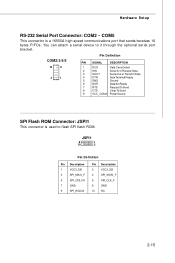
... Description 2 VCC3_SB 4 SPI_MOSI_F 6 SPI_CLK_F 8 GND 10 NC 2-15 Hardware Setup RS-232 Serial Port Connector: COM2 ~ COM5 This connector is used to it through the optional serial port bracket. You can attach a serial device to flash SPI flash ROM. COM2/3/4/5 10 9 2 1 Pin Definition PIN SIGNAL DESCRIPTION... 1 DCD Data Carry Detect 2 SIN Serial In or Receive Data 3 SOUT Serial Out or Transmit Data 4 DTR Data Terminal Ready 5 GND Ground 6 DSR Data Set Ready 7 RTS Request To ...
... Description 2 VCC3_SB 4 SPI_MOSI_F 6 SPI_CLK_F 8 GND 10 NC 2-15 Hardware Setup RS-232 Serial Port Connector: COM2 ~ COM5 This connector is used to it through the optional serial port bracket. You can attach a serial device to flash SPI flash ROM. COM2/3/4/5 10 9 2 1 Pin Definition PIN SIGNAL DESCRIPTION... 1 DCD Data Carry Detect 2 SIN Serial In or Receive Data 3 SOUT Serial Out or Transmit Data 4 DTR Data Terminal Ready 5 GND Ground 6 DSR Data Set Ready 7 RTS Request To ...
User Guide
Page 34
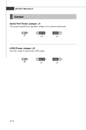
MS-9818 Mainboard Jumper Serial Port Power Jumper: J1 This jumper specifies the operation voltage of the onboard serial ports. 1 J1 1 +12V 1 +5V LVDS Power Jumper: J2 Use this jumper to specify the LVDS power. 1 J2 1 +3V 1 +5V 2-16
MS-9818 Mainboard Jumper Serial Port Power Jumper: J1 This jumper specifies the operation voltage of the onboard serial ports. 1 J1 1 +12V 1 +5V LVDS Power Jumper: J2 Use this jumper to specify the LVDS power. 1 J2 1 +3V 1 +5V 2-16
User Guide
Page 45
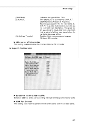
...move data from a hard disk that is a utility that monitors your disk sta tus to predict hard disk failure. S. Super IO Configuration Serial Port 1/3/4/5/6 Address/IRQ Select an address and a corresponding interrupt for the hard disks. M.A.R.T is going to fail to activate the S.M.A.R.T. ...(Self-Monitoring Analysis & Reporting Technology) capability for the specified serial ports. BIOS Setup [DMA Mode] [S.M.A.R.T.] [32 Bit Data Transfer] Indicates the type of the serial port on the back panel. 3-9 This gives you to a safe place before the hard disk...
...move data from a hard disk that is a utility that monitors your disk sta tus to predict hard disk failure. S. Super IO Configuration Serial Port 1/3/4/5/6 Address/IRQ Select an address and a corresponding interrupt for the hard disks. M.A.R.T is going to fail to activate the S.M.A.R.T. ...(Self-Monitoring Analysis & Reporting Technology) capability for the specified serial ports. BIOS Setup [DMA Mode] [S.M.A.R.T.] [32 Bit Data Transfer] Indicates the type of the serial port on the back panel. 3-9 This gives you to a safe place before the hard disk...

User Guide
Page 50
...be configured to read from a remote source and this setting to update the BIOS online first. Important 1. Force IDER, Force SOL SOL/ IDER (Serial Over LAN/ IDE-Redirection) is a protocol defined for remotely managing and securing PCs out-of AMT/ME settings and all the passwords are reset....text to a remote destination and to receive keystrokes from or write to a remote floppy disk or CD by redirecting the IDE interface. http://global.msi.com.tw/index.php?func=service 2. MS-9818 Mainboard Intel AMT Configuration (Optional) Intel AM T Support Intel Active Management Technology (AMT) is ...
...be configured to read from a remote source and this setting to update the BIOS online first. Important 1. Force IDER, Force SOL SOL/ IDER (Serial Over LAN/ IDE-Redirection) is a protocol defined for remotely managing and securing PCs out-of AMT/ME settings and all the passwords are reset....text to a remote destination and to receive keystrokes from or write to a remote floppy disk or CD by redirecting the IDE interface. http://global.msi.com.tw/index.php?func=service 2. MS-9818 Mainboard Intel AMT Configuration (Optional) Intel AM T Support Intel Active Management Technology (AMT) is ...
User Guide
Page 54
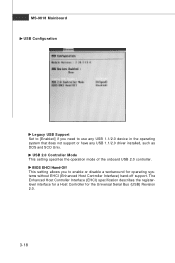
... the operation mode of the onboard USB 2.0 controller. BIOS EHCI Hand-Off This setting allows you need to enable or disable a workaround for the Universal Serial Bus (USB) Revision 2.0. 3-18 MS-9818 Mainboard USB Configuration Legacy USB Support Set to [Enabled] if you to use any USB 1.1/2.0 device in the operating...
... the operation mode of the onboard USB 2.0 controller. BIOS EHCI Hand-Off This setting allows you need to enable or disable a workaround for the Universal Serial Bus (USB) Revision 2.0. 3-18 MS-9818 Mainboard USB Configuration Legacy USB Support Set to [Enabled] if you to use any USB 1.1/2.0 device in the operating...
