
User Guide
Page 2
...174; is a registered trademark of Phoenix Technologies Ltd. Alternatively, please try the following help resources for FAQ, technical guide, BIOS updates, driver updates, and other countries. Visit the MSI website at http://ocss.msi.com.tw. ii Intel® and...INTERNATIONAL. AMD, Athlon™, Athlon™ XP, Thoroughbred™, and Duron™ are under continual improvement and we reserve the right to the correctness of its contents. func=service for further guidance. Copyright Notice The material in this document, but no solution can be obtained from the user's manual...
...174; is a registered trademark of Phoenix Technologies Ltd. Alternatively, please try the following help resources for FAQ, technical guide, BIOS updates, driver updates, and other countries. Visit the MSI website at http://ocss.msi.com.tw. ii Intel® and...INTERNATIONAL. AMD, Athlon™, Athlon™ XP, Thoroughbred™, and Duron™ are under continual improvement and we reserve the right to the correctness of its contents. func=service for further guidance. Copyright Notice The material in this document, but no solution can be obtained from the user's manual...

User Guide
Page 3
... 600 C (1400F), IT MAYDAMAGE THE EQUIPMENT. Replace only with the same or equivalent type recommended by service personnel: The power cord or plug is incorrectly replaced. Keep this equipment away from overheating. Do not place anything over the power cord. 8. If any add-on it. The equipment does not work according to User's Manual. The equipment has dropped and damaged...
... 600 C (1400F), IT MAYDAMAGE THE EQUIPMENT. Replace only with the same or equivalent type recommended by service personnel: The power cord or plug is incorrectly replaced. Keep this equipment away from overheating. Do not place anything over the power cord. 8. If any add-on it. The equipment does not work according to User's Manual. The equipment has dropped and damaged...

User Guide
Page 8
... Support ...ii Safety Instructions ...iii FCC-B Radio Frequency Interference Statement iv W EEE (Waste Electrical and Electronic Equipment) Statement v Chapter 1 Product Overview 1-1 Mainboard Specifications 1-2 Block Diagram ...1-4 Mainboard Layout 1-5 Board Dimension 1-6 Back Panel & I/O Shield Drawing 1-7 Power Consumption 1-8 Safety Compliance & MTBF 1-9 Chapter 2 Hardware Setup 2-1 Quick Components Guide 2-2 Memory ...2-3 CPU (Central Processing Unit 2-4 Power Supply ...2-6 Back Panel ...2-7 Connector ...2-9 Jumper ...2-16 Slot ...2-17 Chapter 3 BIOS Setup 3-1 Entering Setup...
... Support ...ii Safety Instructions ...iii FCC-B Radio Frequency Interference Statement iv W EEE (Waste Electrical and Electronic Equipment) Statement v Chapter 1 Product Overview 1-1 Mainboard Specifications 1-2 Block Diagram ...1-4 Mainboard Layout 1-5 Board Dimension 1-6 Back Panel & I/O Shield Drawing 1-7 Power Consumption 1-8 Safety Compliance & MTBF 1-9 Chapter 2 Hardware Setup 2-1 Quick Components Guide 2-2 Memory ...2-3 CPU (Central Processing Unit 2-4 Power Supply ...2-6 Back Panel ...2-7 Connector ...2-9 Jumper ...2-16 Slot ...2-17 Chapter 3 BIOS Setup 3-1 Entering Setup...
User Guide
Page 9
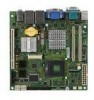
Product Overview Chapter 1 Product Overview Thank you for optimal system efficiency, the IM-GM45 accommodates the latest Intel® Penryn/Core 2 Duo/ Celeron M processors and supports two DDR2 667/ 800MHz SO-DIMM slots to provide the maximum of 4GB memory capacity. Based on the innovative Intel® GM45 & ICH9M-E controllers for choosing the IM-GM45 (MS-9818 v1.X) Mini ITX mainboard from MSI. In the entry-level and mid-range market segment, the IM-GM45 can provide a high-performance solution for today's front-end and general purpose workstation, as well as in the future. 1-1
Product Overview Chapter 1 Product Overview Thank you for optimal system efficiency, the IM-GM45 accommodates the latest Intel® Penryn/Core 2 Duo/ Celeron M processors and supports two DDR2 667/ 800MHz SO-DIMM slots to provide the maximum of 4GB memory capacity. Based on the innovative Intel® GM45 & ICH9M-E controllers for choosing the IM-GM45 (MS-9818 v1.X) Mini ITX mainboard from MSI. In the entry-level and mid-range market segment, the IM-GM45 can provide a high-performance solution for today's front-end and general purpose workstation, as well as in the future. 1-1
User Guide
Page 10
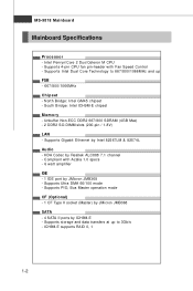
...-E chipset M emor y - Supports PIO, Bus Master operation mode CF (Optional) - 1 CF Type II socket (Master) by JMicron JMB368 SATA - 4 SATA II ports by Realtek ALC888 7.1 channel - Supports Gigabit Ethernet by JMicron JMB368 - Supports Intel Dual Core Technology to 667/800/1066MHz and up to 3Gb/s - Compliant with Fan Speed Control - Supports 4-pin CPU fan pin-header with Azalia 1.0 specs - 6 watt amplifier IDE - 1 IDE port by Intel 82567LM & 82574L Audio - MS-9818 Mainboard Mainboard Specifications Processor - Intel Penryn/Core 2 Duo/Celeron M CPU - ICH9M-E supports RAID...
...-E chipset M emor y - Supports PIO, Bus Master operation mode CF (Optional) - 1 CF Type II socket (Master) by JMicron JMB368 SATA - 4 SATA II ports by Realtek ALC888 7.1 channel - Supports Gigabit Ethernet by JMicron JMB368 - Supports Intel Dual Core Technology to 667/800/1066MHz and up to 3Gb/s - Compliant with Fan Speed Control - Supports 4-pin CPU fan pin-header with Azalia 1.0 specs - 6 watt amplifier IDE - 1 IDE port by Intel 82567LM & 82574L Audio - MS-9818 Mainboard Mainboard Specifications Processor - Intel Penryn/Core 2 Duo/Celeron M CPU - ICH9M-E supports RAID...
User Guide
Page 11
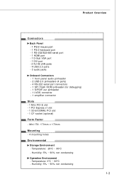
...485 serial port - 1 HDMI port - 1 D-Sub VGA port - 1 DVI port - 2 RJ-45 LAN jacks - 4 USB 2.0 ports - 3 audio jacks Onboard Connectors - 1 front panel audio pinheader - 2 USB 2.0 pinheaders (4 ports) - 4 RS-232 serial port connectors - 1 SPI Flash ROM pinheader (for debugging) - 1 S/PDIF-out pinheader - 1 LVDS connector - 1 amplifier connector Slots - 1 Mini PCI-E slot - 1 PCI Express x1 slot - 1 32-bit/33MHz PCI slot - 1 CF socket (optional) Form Factor - Temperature: -20oC ~ 80oC - Humidity: 5% ~ 90% non condensing 1-3 Mini ITX: 170mm x 170mm Mounting - 4 mounting holes Environmental Storage...
...485 serial port - 1 HDMI port - 1 D-Sub VGA port - 1 DVI port - 2 RJ-45 LAN jacks - 4 USB 2.0 ports - 3 audio jacks Onboard Connectors - 1 front panel audio pinheader - 2 USB 2.0 pinheaders (4 ports) - 4 RS-232 serial port connectors - 1 SPI Flash ROM pinheader (for debugging) - 1 S/PDIF-out pinheader - 1 LVDS connector - 1 amplifier connector Slots - 1 Mini PCI-E slot - 1 PCI Express x1 slot - 1 32-bit/33MHz PCI slot - 1 CF socket (optional) Form Factor - Temperature: -20oC ~ 80oC - Humidity: 5% ~ 90% non condensing 1-3 Mini ITX: 170mm x 170mm Mounting - 4 mounting holes Environmental Storage...
User Guide
Page 24
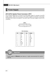
... 13 GND 14 PS_ON 15 GND 16 GND 17 GND 18 -5V 19 5V 20 5V Important Power supply of the power supply is highly recommended for system stability. 2-6 MS-9818 Mainboard Power Supply ATX 20-Pin System Power Connector: ATX1 This connector allows you to connect to the ATX power supply, make sure the plug of 200watts (and above) is inserted in the proper orientation and the...
... 13 GND 14 PS_ON 15 GND 16 GND 17 GND 18 -5V 19 5V 20 5V Important Power supply of the power supply is highly recommended for system stability. 2-6 MS-9818 Mainboard Power Supply ATX 20-Pin System Power Connector: ATX1 This connector allows you to connect to the ATX power supply, make sure the plug of 200watts (and above) is inserted in the proper orientation and the...

User Guide
Page 25
... keyboard, mouse, or other USB-compatible devices. 2-7 To connect an LCD monitor, simply plug your monitor manual for more information.) USB Port The USB (Universal Serial Bus) port is a 16550A high speed communications port that the other serial devices directly to connect an LCD monitor. Hardware Setup Back Panel RS-232/422/485 M ou se Serial Port VGA Port LAN LAN Line-In Line-Out Keyboard HDMI Port DVI Port USB Ports USB Ports MIC M ouse/K ey boar d The standard PS/2® mouse/keyboard DIN connector is an all-digital audio/video...
... keyboard, mouse, or other USB-compatible devices. 2-7 To connect an LCD monitor, simply plug your monitor manual for more information.) USB Port The USB (Universal Serial Bus) port is a 16550A high speed communications port that the other serial devices directly to connect an LCD monitor. Hardware Setup Back Panel RS-232/422/485 M ou se Serial Port VGA Port LAN LAN Line-In Line-Out Keyboard HDMI Port DVI Port USB Ports USB Ports MIC M ouse/K ey boar d The standard PS/2® mouse/keyboard DIN connector is an all-digital audio/video...

User Guide
Page 27
Hardware Setup Connector IDE Connector: IDE1 This connector supports IDE hard disk drives, optical disk drives and other IDE devices. IDE1 Important If you install two IDE devices on the same cable, you must configure the drives separately to IDE device's documentation supplied by setting jumpers. Refer to master / slave mode by the vendors for jumper setting instructions. 2-9
Hardware Setup Connector IDE Connector: IDE1 This connector supports IDE hard disk drives, optical disk drives and other IDE devices. IDE1 Important If you install two IDE devices on the same cable, you must configure the drives separately to IDE device's documentation supplied by setting jumpers. Refer to master / slave mode by the vendors for jumper setting instructions. 2-9
User Guide
Page 30
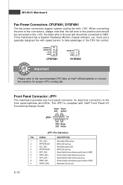
... + 7 RST_SW + 8 PW R_SW - 9 RSVD_DNU DESCRIPTION Hard disk LED pull-up MSG LED pull-up Hard disk active LED MSG LED pull-up Reset Switch low reference pull-down to GND Power Switch high reference pull-up Reset Switch high reference pull-up Power Switch low reference pull-down to take advantage of the CPU fan control. W hen connecting the wire to the connectors, always note that the red wire is the positive and should be...
... + 7 RST_SW + 8 PW R_SW - 9 RSVD_DNU DESCRIPTION Hard disk LED pull-up MSG LED pull-up Hard disk active LED MSG LED pull-up Reset Switch low reference pull-down to GND Power Switch high reference pull-up Reset Switch high reference pull-up Power Switch low reference pull-down to take advantage of the CPU fan control. W hen connecting the wire to the connectors, always note that the red wire is the positive and should be...

User Guide
Page 35
...supports LAN card, SCSI card, USB card, and other add-on cards that you unplug the power supply first. The default set- Hardware Setup Slot PCI (Peripheral Component Interconnect) Express Slot The PCI Express slot supports PCI Express interface expansion cards. ting is Mini PCI-E connector for the expansion card, such as jumpers, switches or BIOS configuration. 2-17 CF1 Important When adding or removing expansion cards, make sure that comply with PCI specifications. 32-bit PCI Slot CompactFlash Card Slot: CF1 (Optional) This CompactFlash slot shares one channel of the IDE controller...
...supports LAN card, SCSI card, USB card, and other add-on cards that you unplug the power supply first. The default set- Hardware Setup Slot PCI (Peripheral Component Interconnect) Express Slot The PCI Express slot supports PCI Express interface expansion cards. ting is Mini PCI-E connector for the expansion card, such as jumpers, switches or BIOS configuration. 2-17 CF1 Important When adding or removing expansion cards, make sure that comply with PCI specifications. 32-bit PCI Slot CompactFlash Card Slot: CF1 (Optional) This CompactFlash slot shares one channel of the IDE controller...
User Guide
Page 43
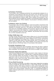
... its requirements and prefetches data and instructions from the memory into the Level 2 cache that are likely to be disabled. Adjacent Cache Line Prefetch The processor has a hardware adjacent cache line prefetch mechanism that do not support the Intel Pentium 4 processor with a supporting operating system. Intel(R) Virtualization Tech Virtualization enhanced by Intel Virtualization Technology will be enabled and allowed to classify areas...
... its requirements and prefetches data and instructions from the memory into the Level 2 cache that are likely to be disabled. Adjacent Cache Line Prefetch The processor has a hardware adjacent cache line prefetch mechanism that do not support the Intel Pentium 4 processor with a supporting operating system. Intel(R) Virtualization Tech Virtualization enhanced by Intel Virtualization Technology will be enabled and allowed to classify areas...
User Guide
Page 44
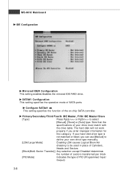
... except Disabled determines the number of sectors transferred per block [PIO Mode] Indicates the type of SATA ports. Configure SATA#1 as This setting specifies the function of your hard disk drive type is not matched or listed, you enter improper information for this category. Note that the specifications of the on-chip SATA controller. SATA#1 Configuration This setting specifies the operation mode of PIO (Programmed Input/ Output) 3-8 dressing to select [Manual], [None] or [Auto] type.
... except Disabled determines the number of sectors transferred per block [PIO Mode] Indicates the type of SATA ports. Configure SATA#1 as This setting specifies the function of your hard disk drive type is not matched or listed, you enter improper information for this category. Note that the specifications of the on-chip SATA controller. SATA#1 Configuration This setting specifies the operation mode of PIO (Programmed Input/ Output) 3-8 dressing to select [Manual], [None] or [Auto] type.
User Guide
Page 45
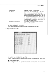
... to fail to predict hard disk failure. Enables 32-bit communication between CPU and IDE controller JMicron 36x ATA Controller This setting enables/disables the onboard JMicron IDE controller. Super IO Configuration Serial Port 1/3/4/5/6 Address/IRQ Select an address and a corresponding interrupt for the hard disks. S. This gives you to activate the S.M.A.R.T. (Self-Monitoring Analysis & Reporting Technology) capability for the specified serial ports. BIOS Setup [DMA Mode] [S.M.A.R.T.] [32 Bit Data Transfer] Indicates the type of the serial port on the back panel. 3-9
... to fail to predict hard disk failure. Enables 32-bit communication between CPU and IDE controller JMicron 36x ATA Controller This setting enables/disables the onboard JMicron IDE controller. Super IO Configuration Serial Port 1/3/4/5/6 Address/IRQ Select an address and a corresponding interrupt for the hard disks. S. This gives you to activate the S.M.A.R.T. (Self-Monitoring Analysis & Reporting Technology) capability for the specified serial ports. BIOS Setup [DMA Mode] [S.M.A.R.T.] [32 Bit Data Transfer] Indicates the type of the serial port on the back panel. 3-9

User Guide
Page 46
.../SYSFAN1/SYSFAN2 TargetSpeed Value" items. If the current fan 3-10 CPUFAN1 Mode Setting, SYSFAN1 Mode Setting This item enables or disables the Smart Fan feature. MS-9818 Mainboard Hardware Health Configuration These items display the current status of the CPU/system fan to prevent your system from overheating. Smart Fan is an excellent feature which will automatically increase the speed of the monitored hardware devices/components such as voltages and temperatures.
.../SYSFAN1/SYSFAN2 TargetSpeed Value" items. If the current fan 3-10 CPUFAN1 Mode Setting, SYSFAN1 Mode Setting This item enables or disables the Smart Fan feature. MS-9818 Mainboard Hardware Health Configuration These items display the current status of the CPU/system fan to prevent your system from overheating. Smart Fan is an excellent feature which will automatically increase the speed of the monitored hardware devices/components such as voltages and temperatures.

User Guide
Page 47
... value here for the specific range for the "CPUFAN1/SYSFAN1 TargetTemp Value" items. If the current temperatures of the CPU/system fan to the maximum threshold (the temperatures set in the "CPUFAN1/ SYSFAN1 TargetSpeed Value" plus the tolerance values you set here), the fans will speed up for cooling down. BIOS Setup speeds reach the maximum threshold (the fan speed set in the "CPUFAN1/SYSFAN1...
... value here for the specific range for the "CPUFAN1/SYSFAN1 TargetTemp Value" items. If the current temperatures of the CPU/system fan to the maximum threshold (the temperatures set in the "CPUFAN1/ SYSFAN1 TargetSpeed Value" plus the tolerance values you set here), the fans will speed up for cooling down. BIOS Setup speeds reach the maximum threshold (the fan speed set in the "CPUFAN1/SYSFAN1...

User Guide
Page 50
... source and this setting to as Serial Over LAN. http://global.msi.com.tw/index.php?func=service 2. In order to manage a system remotely we need to a remote workstation. MS-9818 Mainboard Intel AMT Configuration (Optional) Intel AM T Support Intel Active Management Technology (AMT) is hardware-based technology for Intel Active Management Technology that allows redirecting the keyboard/text or floppy disk/CD transfers from...
... source and this setting to as Serial Over LAN. http://global.msi.com.tw/index.php?func=service 2. In order to manage a system remotely we need to a remote workstation. MS-9818 Mainboard Intel AMT Configuration (Optional) Intel AM T Support Intel Active Management Technology (AMT) is hardware-based technology for Intel Active Management Technology that allows redirecting the keyboard/text or floppy disk/CD transfers from...
User Guide
Page 54
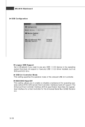
MS-9818 Mainboard USB Configuration Legacy USB Support Set to [Enabled] if you to use any USB 1.1/2.0 device in the operating system that does not support or have any USB 1.1/2.0 driver installed, such as DOS and SCO Unix. USB 2.0 Controller Mode This setting specifies the operation mode of the onboard USB 2.0 controller. BIOS EHCI Hand-Off This setting allows you need to enable or disable a workaround for the Universal Serial Bus (USB) Revision 2.0. 3-18 The Enhanced Host Controller Interface (EHCI) specification describes the...
MS-9818 Mainboard USB Configuration Legacy USB Support Set to [Enabled] if you to use any USB 1.1/2.0 device in the operating system that does not support or have any USB 1.1/2.0 driver installed, such as DOS and SCO Unix. USB 2.0 Controller Mode This setting specifies the operation mode of the onboard USB 2.0 controller. BIOS EHCI Hand-Off This setting allows you need to enable or disable a workaround for the Universal Serial Bus (USB) Revision 2.0. 3-18 The Enhanced Host Controller Interface (EHCI) specification describes the...
User Guide
Page 56
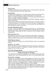
... Mainboard Quick Boot Enabling this setting will cause the BIOS power-on the first BIOS screen when the computer boots. AddOn ROM Display M ode This item is used to determine the display mode when an optional ROM is set to run setup It will allow users to these adaptors can function as follows: Hit Del if you will not be able to the host adaptor's ROM setup utility, if one is disabled, the BIOS...
... Mainboard Quick Boot Enabling this setting will cause the BIOS power-on the first BIOS screen when the computer boots. AddOn ROM Display M ode This item is used to determine the display mode when an optional ROM is set to run setup It will allow users to these adaptors can function as follows: Hit Del if you will not be able to the host adaptor's ROM setup utility, if one is disabled, the BIOS...
User Guide
Page 60
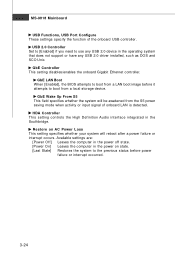
GbE Controller This setting disables/enables the onboard Gigabit Ethernet controller. GbE Wake Up From S5 This field specifies whether the system will reboot after a power failure or interrupt occurs. HDA Controller This setting controls the High Definition Audio interface integrated in the operating system that does not support or have any USB 2.0 driver installed, such as DOS and SCO Unix. GbE LAN Boot W hen [Enabled], the BIOS attempts to boot from a LAN boot image before...
GbE Controller This setting disables/enables the onboard Gigabit Ethernet controller. GbE Wake Up From S5 This field specifies whether the system will reboot after a power failure or interrupt occurs. HDA Controller This setting controls the High Definition Audio interface integrated in the operating system that does not support or have any USB 2.0 driver installed, such as DOS and SCO Unix. GbE LAN Boot W hen [Enabled], the BIOS attempts to boot from a LAN boot image before...


