User Guide
Page 11
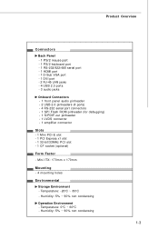
...90% non condensing 1-3 Mini ITX: 170mm x 170mm Mounting - 4 mounting holes Environmental Storage Environment - Temperature: -20oC ~ 80oC - Humidity: 5% ~ 90% non condensing Operation Environment - Product Overview Connectors Back Panel - 1 PS/2 mouse port - 1 PS/2 keyboard port - 1 RS-232/422/485 serial port - 1 HDMI... panel audio pinheader - 2 USB 2.0 pinheaders (4 ports) - 4 RS-232 serial port connectors - 1 SPI Flash ROM pinheader (for debugging) - 1 S/PDIF-out pinheader - 1 LVDS connector - 1 amplifier connector Slots - 1 Mini PCI-E slot - 1 PCI Express x1 slot - 1 32-bit/33MHz PCI slot...
...90% non condensing 1-3 Mini ITX: 170mm x 170mm Mounting - 4 mounting holes Environmental Storage Environment - Temperature: -20oC ~ 80oC - Humidity: 5% ~ 90% non condensing Operation Environment - Product Overview Connectors Back Panel - 1 PS/2 mouse port - 1 PS/2 keyboard port - 1 RS-232/422/485 serial port - 1 HDMI... panel audio pinheader - 2 USB 2.0 pinheaders (4 ports) - 4 RS-232 serial port connectors - 1 SPI Flash ROM pinheader (for debugging) - 1 S/PDIF-out pinheader - 1 LVDS connector - 1 amplifier connector Slots - 1 Mini PCI-E slot - 1 PCI Express x1 slot - 1 32-bit/33MHz PCI slot...
User Guide
Page 13
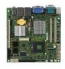
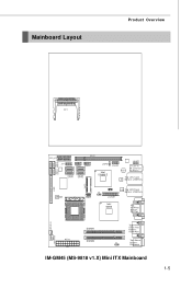
Mainboard Layout Product Overview CF1 PCI_ E1 COM2 COM4 COM3 COM5 PCI1 JFP1 JUSB1 JUSB2 SATA2 SATA1 SATA4 SATA3 JSPD1 Intel ICH9M-E JAU D1 Audio JAMP1 T: Line-In M: Line-Out B: Mic-In Top: LAN1 Jack LAN Bottom: USB Ports CON1 IDE 1 JMB368 JSPI 1 LAN Top: LAN2 Jack J2 Bottom: USB Ports JLVDS1 Intel GM45 To p: VGA Port Bot to m: DVI Port SY S FA N 1 ATX1 DIMM1 DIMM2 To p: Serial Port Bot to m: HDMI Port Top: Mouse J1 Bottom: Keybo ard C P UF AN 1 IM-GM45 (MS-9818 v1.X) Mini ITX Mainboard 1-5
Mainboard Layout Product Overview CF1 PCI_ E1 COM2 COM4 COM3 COM5 PCI1 JFP1 JUSB1 JUSB2 SATA2 SATA1 SATA4 SATA3 JSPD1 Intel ICH9M-E JAU D1 Audio JAMP1 T: Line-In M: Line-Out B: Mic-In Top: LAN1 Jack LAN Bottom: USB Ports CON1 IDE 1 JMB368 JSPI 1 LAN Top: LAN2 Jack J2 Bottom: USB Ports JLVDS1 Intel GM45 To p: VGA Port Bot to m: DVI Port SY S FA N 1 ATX1 DIMM1 DIMM2 To p: Serial Port Bot to m: HDMI Port Top: Mouse J1 Bottom: Keybo ard C P UF AN 1 IM-GM45 (MS-9818 v1.X) Mini ITX Mainboard 1-5

User Guide
Page 25
... is for a PS/2® mouse/keyboard. It provides a high-speed digital interconnection between the computer and its display device. You can attach a serial mouse or other end of the cable is an all-digital audio/video interface capable of transmitting uncompressed streams. HDMI supports all TV format, including... enhanced, or high-definition video, plus multi-channel digital audio on a single cable. Hardware Setup Back Panel RS-232/422/485 M ou se Serial Port VGA Port LAN LAN Line-In Line-Out Keyboard HDMI Port DVI Port USB Ports USB Ports MIC M ouse/K ey boar d The standard PS...
... is for a PS/2® mouse/keyboard. It provides a high-speed digital interconnection between the computer and its display device. You can attach a serial mouse or other end of the cable is an all-digital audio/video interface capable of transmitting uncompressed streams. HDMI supports all TV format, including... enhanced, or high-definition video, plus multi-channel digital audio on a single cable. Hardware Setup Back Panel RS-232/422/485 M ou se Serial Port VGA Port LAN LAN Line-In Line-Out Keyboard HDMI Port DVI Port USB Ports USB Ports MIC M ouse/K ey boar d The standard PS...
User Guide
Page 28
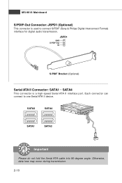
Each connector can connect to connect S/PDIF (Sony & Philips Digital Interconnect Format) interface for digital audio transmission. SATA2 SATA4 SATA1 SATA3 Important Please do not fold the Serial ATA cable into 90-degree angle. JSPD1 GND S/PDIF-Out 5V S/PDIF Bracket (Optional) Serial ATA II Connector: SATA1 ~ SATA4 This connector is used to one Serial ATA II device. MS-9818 Mainboard S/PDIF-Out Connector: JSPD1 (Optional) This connector is a high-speed Serial ATA II interface port. Otherwise, data loss may occur during transmission. 2-10
Each connector can connect to connect S/PDIF (Sony & Philips Digital Interconnect Format) interface for digital audio transmission. SATA2 SATA4 SATA1 SATA3 Important Please do not fold the Serial ATA cable into 90-degree angle. JSPD1 GND S/PDIF-Out 5V S/PDIF Bracket (Optional) Serial ATA II Connector: SATA1 ~ SATA4 This connector is used to one Serial ATA II device. MS-9818 Mainboard S/PDIF-Out Connector: JSPD1 (Optional) This connector is a high-speed Serial ATA II interface port. Otherwise, data loss may occur during transmission. 2-10
User Guide
Page 33
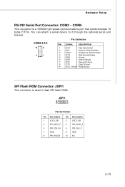
... to flash SPI flash ROM. COM2/3/4/5 10 9 2 1 Pin Definition PIN SIGNAL DESCRIPTION 1 DCD Data Carry Detect 2 SIN Serial In or Receive Data 3 SOUT Serial Out or Transmit Data 4 DTR Data Terminal Ready 5 GND Ground 6 DSR Data Set Ready 7 RTS Request To Send 8 CTS Clear To Send 9 VCC_COM3 PowerSource SPI ...
... to flash SPI flash ROM. COM2/3/4/5 10 9 2 1 Pin Definition PIN SIGNAL DESCRIPTION 1 DCD Data Carry Detect 2 SIN Serial In or Receive Data 3 SOUT Serial Out or Transmit Data 4 DTR Data Terminal Ready 5 GND Ground 6 DSR Data Set Ready 7 RTS Request To Send 8 CTS Clear To Send 9 VCC_COM3 PowerSource SPI ...
User Guide
Page 34
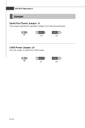
MS-9818 Mainboard Jumper Serial Port Power Jumper: J1 This jumper specifies the operation voltage of the onboard serial ports. 1 J1 1 +12V 1 +5V LVDS Power Jumper: J2 Use this jumper to specify the LVDS power. 1 J2 1 +3V 1 +5V 2-16
MS-9818 Mainboard Jumper Serial Port Power Jumper: J1 This jumper specifies the operation voltage of the onboard serial ports. 1 J1 1 +12V 1 +5V LVDS Power Jumper: J2 Use this jumper to specify the LVDS power. 1 J2 1 +3V 1 +5V 2-16
User Guide
Page 45
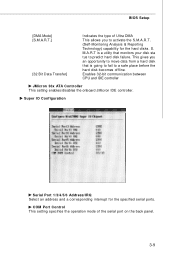
Super IO Configuration Serial Port 1/3/4/5/6 Address/IRQ Select an address and a corresponding interrupt for the hard disks. Enables 32-bit communication between CPU and IDE controller JMicron 36x ATA ... a hard disk that is a utility that monitors your disk sta tus to activate the S.M.A.R.T. (Self-Monitoring Analysis & Reporting Technology) capability for the specified serial ports. BIOS Setup [DMA Mode] [S.M.A.R.T.] [32 Bit Data Transfer] Indicates the type of the serial port on the back panel. 3-9 S. This gives you to predict hard disk failure.
Super IO Configuration Serial Port 1/3/4/5/6 Address/IRQ Select an address and a corresponding interrupt for the hard disks. Enables 32-bit communication between CPU and IDE controller JMicron 36x ATA ... a hard disk that is a utility that monitors your disk sta tus to activate the S.M.A.R.T. (Self-Monitoring Analysis & Reporting Technology) capability for the specified serial ports. BIOS Setup [DMA Mode] [S.M.A.R.T.] [32 Bit Data Transfer] Indicates the type of the serial port on the back panel. 3-9 S. This gives you to predict hard disk failure.

User Guide
Page 50
The platform can also be configured to read from a local host to a remote workstation. http://global.msi.com.tw/index.php?func=service 2. Important 1. Force IDER, Force SOL SOL/ IDER (Serial Over LAN/ IDE-Redirection) is a protocol defined for remotely managing and securing PCs out-of AMT/ME settings and all the passwords... Intel AMT function, you need a capability to send console text to a remote destination and to receive keystrokes from a remote source and this setting to as Serial Over LAN.
The platform can also be configured to read from a local host to a remote workstation. http://global.msi.com.tw/index.php?func=service 2. Important 1. Force IDER, Force SOL SOL/ IDER (Serial Over LAN/ IDE-Redirection) is a protocol defined for remotely managing and securing PCs out-of AMT/ME settings and all the passwords... Intel AMT function, you need a capability to send console text to a remote destination and to receive keystrokes from a remote source and this setting to as Serial Over LAN.
User Guide
Page 54
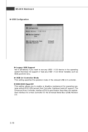
... the operation mode of the onboard USB 2.0 controller. BIOS EHCI Hand-Off This setting allows you need to enable or disable a workaround for the Universal Serial Bus (USB) Revision 2.0. 3-18 The Enhanced Host Controller Interface (EHCI) specification describes the registerlevel interface for a Host Controller for operating systems without EHCI (Enhanced Host...
... the operation mode of the onboard USB 2.0 controller. BIOS EHCI Hand-Off This setting allows you need to enable or disable a workaround for the Universal Serial Bus (USB) Revision 2.0. 3-18 The Enhanced Host Controller Interface (EHCI) specification describes the registerlevel interface for a Host Controller for operating systems without EHCI (Enhanced Host...
