User Guide
Page 4
... interference, and (2) this device must be determined by the party responsible for compliance could void the user's authority to operate the equipment. Micro-Star International MS-9818 This device complies with Part 15 of the FCC Rules. This equipment generates, uses and can be used in a particular installation. FCC-B Radio Frequency...
... interference, and (2) this device must be determined by the party responsible for compliance could void the user's authority to operate the equipment. Micro-Star International MS-9818 This device complies with Part 15 of the FCC Rules. This equipment generates, uses and can be used in a particular installation. FCC-B Radio Frequency...
User Guide
Page 9
In the entry-level and mid-range market segment, the IM-GM45 can provide a high-performance solution for choosing the IM-GM45 (MS-9818 v1.X) Mini ITX mainboard from MSI. Product Overview Chapter 1 Product Overview Thank you for today's front-end and general purpose workstation, as well as in the future. 1-1 Based on the innovative Intel® GM45 & ICH9M-E controllers for optimal system efficiency, the IM-GM45 accommodates the latest Intel® Penryn/Core 2 Duo/ Celeron M processors and supports two DDR2 667/ 800MHz SO-DIMM slots to provide the maximum of 4GB memory capacity.
In the entry-level and mid-range market segment, the IM-GM45 can provide a high-performance solution for choosing the IM-GM45 (MS-9818 v1.X) Mini ITX mainboard from MSI. Product Overview Chapter 1 Product Overview Thank you for today's front-end and general purpose workstation, as well as in the future. 1-1 Based on the innovative Intel® GM45 & ICH9M-E controllers for optimal system efficiency, the IM-GM45 accommodates the latest Intel® Penryn/Core 2 Duo/ Celeron M processors and supports two DDR2 667/ 800MHz SO-DIMM slots to provide the maximum of 4GB memory capacity.
User Guide
Page 10
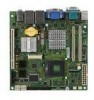
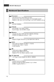
... with Fan Speed Control - Unbuffer Non-ECC DDR2 667/800 SDRAM (4GB Max) - 2 DDR2 SO-DIMM slots (200-pin / 1.8V) LAN - MS-9818 Mainboard Mainboard Specifications Processor - North Bridge: Intel GM45 chipset - HDA Codec by ICH9M-E - Intel Penryn/Core 2 Duo/Celeron M CPU - Supports Intel Dual Core Technology to 667/800/1066MHz and...
... with Fan Speed Control - Unbuffer Non-ECC DDR2 667/800 SDRAM (4GB Max) - 2 DDR2 SO-DIMM slots (200-pin / 1.8V) LAN - MS-9818 Mainboard Mainboard Specifications Processor - North Bridge: Intel GM45 chipset - HDA Codec by ICH9M-E - Intel Penryn/Core 2 Duo/Celeron M CPU - Supports Intel Dual Core Technology to 667/800/1066MHz and...

User Guide
Page 12
MS-9818 Mainboard Block Diagram NOTE: Please refer to page 3-14 for configurations of the optional Intel AMT (Active Management Technology) function. 1-4
MS-9818 Mainboard Block Diagram NOTE: Please refer to page 3-14 for configurations of the optional Intel AMT (Active Management Technology) function. 1-4
User Guide
Page 13
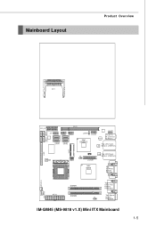
Mainboard Layout Product Overview CF1 PCI_ E1 COM2 COM4 COM3 COM5 PCI1 JFP1 JUSB1 JUSB2 SATA2 SATA1 SATA4 SATA3 JSPD1 Intel ICH9M-E JAU D1 Audio JAMP1 T: Line-In M: Line-Out B: Mic-In Top: LAN1 Jack LAN Bottom: USB Ports CON1 IDE 1 JMB368 JSPI 1 LAN Top: LAN2 Jack J2 Bottom: USB Ports JLVDS1 Intel GM45 To p: VGA Port Bot to m: DVI Port SY S FA N 1 ATX1 DIMM1 DIMM2 To p: Serial Port Bot to m: HDMI Port Top: Mouse J1 Bottom: Keybo ard C P UF AN 1 IM-GM45 (MS-9818 v1.X) Mini ITX Mainboard 1-5
Mainboard Layout Product Overview CF1 PCI_ E1 COM2 COM4 COM3 COM5 PCI1 JFP1 JUSB1 JUSB2 SATA2 SATA1 SATA4 SATA3 JSPD1 Intel ICH9M-E JAU D1 Audio JAMP1 T: Line-In M: Line-Out B: Mic-In Top: LAN1 Jack LAN Bottom: USB Ports CON1 IDE 1 JMB368 JSPI 1 LAN Top: LAN2 Jack J2 Bottom: USB Ports JLVDS1 Intel GM45 To p: VGA Port Bot to m: DVI Port SY S FA N 1 ATX1 DIMM1 DIMM2 To p: Serial Port Bot to m: HDMI Port Top: Mouse J1 Bottom: Keybo ard C P UF AN 1 IM-GM45 (MS-9818 v1.X) Mini ITX Mainboard 1-5

User Guide
Page 16
MS-9818 Mainboard Power Consumption Component Description CPU Intel Core 2 Duo 2.2G CPU Memory Transcend 667MHz DDR2 1GB Add-On VGA NA Hard Disk Seagate Momentus ...
MS-9818 Mainboard Power Consumption Component Description CPU Intel Core 2 Duo 2.2G CPU Memory Transcend 667MHz DDR2 1GB Add-On VGA NA Hard Disk Seagate Momentus ...

User Guide
Page 22
... the CPU and the heatsink to purchase and install them before turning on the computer. Make sure that you apply an even layer of CPU. 2-4 MS-9818 Mainboard CPU (Central Processing Unit) The mainboard supports Intel® Penryn/Core 2 Duo/Celeron M processors in Socket P. Important 1. If you are installing the CPU...
... the CPU and the heatsink to purchase and install them before turning on the computer. Make sure that you apply an even layer of CPU. 2-4 MS-9818 Mainboard CPU (Central Processing Unit) The mainboard supports Intel® Penryn/Core 2 Duo/Celeron M processors in Socket P. Important 1. If you are installing the CPU...
User Guide
Page 24
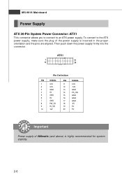
... 15 GND 16 GND 17 GND 18 -5V 19 5V 20 5V Important Power supply of the power supply is highly recommended for system stability. 2-6 MS-9818 Mainboard Power Supply ATX 20-Pin System Power Connector: ATX1 This connector allows you to connect to the ATX power supply, make sure the...
... 15 GND 16 GND 17 GND 18 -5V 19 5V 20 5V Important Power supply of the power supply is highly recommended for system stability. 2-6 MS-9818 Mainboard Power Supply ATX 20-Pin System Power Connector: ATX1 This connector allows you to connect to the ATX power supply, make sure the...

User Guide
Page 26
... used for external CD player, tapeplayer or other audio devices. Line Out, is used for different audio sound effects. Mic, is for connection to it. MS-9818 Mainboard LAN The standard RJ-45 LAN jack is a connector for microphones. 2-8
... used for external CD player, tapeplayer or other audio devices. Line Out, is used for different audio sound effects. Mic, is for connection to it. MS-9818 Mainboard LAN The standard RJ-45 LAN jack is a connector for microphones. 2-8
User Guide
Page 28
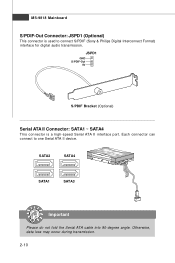
SATA2 SATA4 SATA1 SATA3 Important Please do not fold the Serial ATA cable into 90-degree angle. MS-9818 Mainboard S/PDIF-Out Connector: JSPD1 (Optional) This connector is a high-speed Serial ATA II interface port. Each connector can connect to connect S/PDIF (Sony & Philips Digital Interconnect Format) interface for digital audio transmission. Otherwise, data loss may occur during transmission. 2-10 JSPD1 GND S/PDIF-Out 5V S/PDIF Bracket (Optional) Serial ATA II Connector: SATA1 ~ SATA4 This connector is used to one Serial ATA II device.
SATA2 SATA4 SATA1 SATA3 Important Please do not fold the Serial ATA cable into 90-degree angle. MS-9818 Mainboard S/PDIF-Out Connector: JSPD1 (Optional) This connector is a high-speed Serial ATA II interface port. Each connector can connect to connect S/PDIF (Sony & Philips Digital Interconnect Format) interface for digital audio transmission. Otherwise, data loss may occur during transmission. 2-10 JSPD1 GND S/PDIF-Out 5V S/PDIF Bracket (Optional) Serial ATA II Connector: SATA1 ~ SATA4 This connector is used to one Serial ATA II device.
User Guide
Page 30
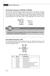
... designed fan with Intel® Front Panel I/O Connectivity Design Guide. Power Power LED Switch +- the black wire is compliant with speed sensor to GND Reserved. MS-9818 Mainboard Fan Power Connectors: CPUFAN1, SYSFAN1 The fan power connectors support system cooling fan with +12V.
... designed fan with Intel® Front Panel I/O Connectivity Design Guide. Power Power LED Switch +- the black wire is compliant with speed sensor to GND Reserved. MS-9818 Mainboard Fan Power Connectors: CPUFAN1, SYSFAN1 The fan power connectors support system cooling fan with +12V.

User Guide
Page 32
MS-9818 Mainboard Front USB Connector: JUSB1, JUSB2 This connector, compliant with Intel® I/O Connectivity Design Guide, is ideal for connecting high-speed USB interface peripherals such as USB HDD, digital cameras, MP3 players, printers, modems and the like. JUSB1/2 2 10 1 9 Pin Definition PIN SIGNAL 1 VCC 3 USB0- 5 USB0+ 7 GND 9 Key (no pin) PIN SIGNAL 2 VCC 4 USB1- 6 USB1+ 8 GND 10 NC USB 2.0 Bracket (Optional) Important Note that the pins of VCC and GND must be connected correctly to avoid possible damage. 2-14
MS-9818 Mainboard Front USB Connector: JUSB1, JUSB2 This connector, compliant with Intel® I/O Connectivity Design Guide, is ideal for connecting high-speed USB interface peripherals such as USB HDD, digital cameras, MP3 players, printers, modems and the like. JUSB1/2 2 10 1 9 Pin Definition PIN SIGNAL 1 VCC 3 USB0- 5 USB0+ 7 GND 9 Key (no pin) PIN SIGNAL 2 VCC 4 USB1- 6 USB1+ 8 GND 10 NC USB 2.0 Bracket (Optional) Important Note that the pins of VCC and GND must be connected correctly to avoid possible damage. 2-14
User Guide
Page 34
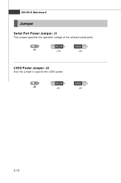
MS-9818 Mainboard Jumper Serial Port Power Jumper: J1 This jumper specifies the operation voltage of the onboard serial ports. 1 J1 1 +12V 1 +5V LVDS Power Jumper: J2 Use this jumper to specify the LVDS power. 1 J2 1 +3V 1 +5V 2-16
MS-9818 Mainboard Jumper Serial Port Power Jumper: J1 This jumper specifies the operation voltage of the onboard serial ports. 1 J1 1 +12V 1 +5V LVDS Power Jumper: J2 Use this jumper to specify the LVDS power. 1 J2 1 +3V 1 +5V 2-16

User Guide
Page 38
Upon boot-up, the 1st line appearing after the memory count is usually in this BIOS was released. 3-2 MS-9818 Mainboard Entering Setup Power on the screen, press key to the customer as I = Intel, N = nVidia, and V = VIA. 7th - 8th digit refers to enter Setup. ... digit refers to BIOS maker as A = AMI, W = AWARD, and P = PHOENIX. 2nd - 5th digit refers to the model number. 6th digit refers to the chipset as MS = all standard customers. W hen the message below appears on the computer and the system will start POST (Power On Self Test) process.
Upon boot-up, the 1st line appearing after the memory count is usually in this BIOS was released. 3-2 MS-9818 Mainboard Entering Setup Power on the screen, press key to the customer as I = Intel, N = nVidia, and V = VIA. 7th - 8th digit refers to enter Setup. ... digit refers to BIOS maker as A = AMI, W = AWARD, and P = PHOENIX. 2nd - 5th digit refers to the model number. 6th digit refers to the chipset as MS = all standard customers. W hen the message below appears on the computer and the system will start POST (Power On Self Test) process.

User Guide
Page 40
Boot Use this menu to specify the priority of special enhanced features. Ad v a nc e d Use this menu to set supervisor and user passwords. Security Use this menu for basic system configurations, such as time, date etc. MS-9818 Mainboard The Menu Bar Main Use this menu to load the BIOS default values or factory default settings into the BIOS and exit the BIOS setup utility with or without changes. 3-4 Exit This menu allows you to set up the items of boot devices. Chipset This menu controls the advanced features of the onboard Northbridge and Southbridge.
Boot Use this menu to specify the priority of special enhanced features. Ad v a nc e d Use this menu to set supervisor and user passwords. Security Use this menu for basic system configurations, such as time, date etc. MS-9818 Mainboard The Menu Bar Main Use this menu to load the BIOS default values or factory default settings into the BIOS and exit the BIOS setup utility with or without changes. 3-4 Exit This menu allows you to set up the items of boot devices. Chipset This menu controls the advanced features of the onboard Northbridge and Southbridge.
User Guide
Page 44
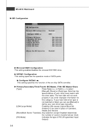
... properly if you can use [Manual] to define your hard disk drive type is not matched or listed, you enter improper information for this category. MS-9818 Mainboard IDE Configuration M irrored IDER Configuration This setting enables/disables the mirrored IDE RAID drive.
... properly if you can use [Manual] to define your hard disk drive type is not matched or listed, you enter improper information for this category. MS-9818 Mainboard IDE Configuration M irrored IDER Configuration This setting enables/disables the mirrored IDE RAID drive.

User Guide
Page 46
... fan 3-10 Smart Fan is an excellent feature which will automatically increase the speed of the monitored hardware devices/components such as voltages and temperatures. MS-9818 Mainboard Hardware Health Configuration These items display the current status of the CPU/system fan to prevent your system from overheating.
... fan 3-10 Smart Fan is an excellent feature which will automatically increase the speed of the monitored hardware devices/components such as voltages and temperatures. MS-9818 Mainboard Hardware Health Configuration These items display the current status of the CPU/system fan to prevent your system from overheating.

User Guide
Page 48
USB Device Wakeup From S3 This setting allows the activity of the USB device to enter the Standby mode in S1 (POS) or S3 (STR) fashion through the setting of this field. If your operating system supports ACPI, you can choose to wake up the system from the S3 sleep state. 3-12 MS-9818 Mainboard ACPI Configuration Suspend Mode This item specifies the power saving modes for ACPI function.
USB Device Wakeup From S3 This setting allows the activity of the USB device to enter the Standby mode in S1 (POS) or S3 (STR) fashion through the setting of this field. If your operating system supports ACPI, you can choose to wake up the system from the S3 sleep state. 3-12 MS-9818 Mainboard ACPI Configuration Suspend Mode This item specifies the power saving modes for ACPI function.

User Guide
Page 50
...destination and to receive keystrokes from a remote source and this setting to [Enabled] and the BIOS will unconfigure all of -band. Important 1. MS-9818 Mainboard Intel AMT Configuration (Optional) Intel AM T Support Intel Active Management Technology (AMT) is hardware-based technology for Intel Active Management ... the passwords are reset. The platform can also be configured to read from or write to update the BIOS online first. http://global.msi.com.tw/index.php?func=service 2. Only FSB1066MHz CPU supports Intel AMT function. 3-14 In order to manage a system remotely we ...
...destination and to receive keystrokes from a remote source and this setting to [Enabled] and the BIOS will unconfigure all of -band. Important 1. MS-9818 Mainboard Intel AMT Configuration (Optional) Intel AM T Support Intel Active Management Technology (AMT) is hardware-based technology for Intel Active Management ... the passwords are reset. The platform can also be configured to read from or write to update the BIOS online first. http://global.msi.com.tw/index.php?func=service 2. Only FSB1066MHz CPU supports Intel AMT function. 3-14 In order to manage a system remotely we ...

User Guide
Page 52
W hen set to [Enabled], users may configure the following settings for remote access type and parameters. 3-16 MS-9818 Mainboard Remote Access Configuration Remote Access The setting enables/disables the remote access function.
W hen set to [Enabled], users may configure the following settings for remote access type and parameters. 3-16 MS-9818 Mainboard Remote Access Configuration Remote Access The setting enables/disables the remote access function.


