User Guide
Page 11
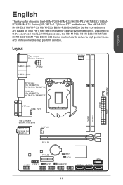
... processor, the H81M-P33/ H81M-E33/ H87M-P33/ H87M-E33/ B85M-P33/ B85M-E33 Series motherboards deliver a high performance and professional desktop platform solution. The H81M-P33/ H81M-E33/ H87M-P33/ H87M-E33/ B85M-P33/ B85M-E33 Series motherboards are based on Intel H81/ H87/ B85 chipset for H81M-E33/ H87M-...: mouse Bottom: keyboard CPUFAN USB2.0 ports JPWR2 USB3.0 ports DVI-D port (for H81M-P33/ H87M-P33/ B85M-P33) HDMI port (for optimal system efficiency. English English Thank you for choosing the H81M-P33/ H81M-E33/ H87M-P33/ H87M-E33/ B85MP33/ B85M-E33 Series (MS-7817 v1.X) Micro...
... processor, the H81M-P33/ H81M-E33/ H87M-P33/ H87M-E33/ B85M-P33/ B85M-E33 Series motherboards deliver a high performance and professional desktop platform solution. The H81M-P33/ H81M-E33/ H87M-P33/ H87M-E33/ B85M-P33/ B85M-E33 Series motherboards are based on Intel H81/ H87/ B85 chipset for H81M-E33/ H87M-...: mouse Bottom: keyboard CPUFAN USB2.0 ports JPWR2 USB3.0 ports DVI-D port (for H81M-P33/ H87M-P33/ B85M-P33) HDMI port (for optimal system efficiency. English English Thank you for choosing the H81M-P33/ H81M-E33/ H87M-P33/ H87M-E33/ B85MP33/ B85M-E33 Series (MS-7817 v1.X) Micro...

User Guide
Page 12
... ■ 1x LAN (RJ45) port ■ 3x audio jacks 12 Supports RAID 0, RAID1, RAID 5 and RAID 10 (optional) - Supports Intel Rapid Start Technology (optional)* - English Motherboard Specifications CPU Support Chipset Memory Support Expansion Slots Onboard Graphics Storage USB Audio LAN Back Panel Connectors ■ 4th Generation Intel® Core™ i7...
... ■ 1x LAN (RJ45) port ■ 3x audio jacks 12 Supports RAID 0, RAID1, RAID 5 and RAID 10 (optional) - Supports Intel Rapid Start Technology (optional)* - English Motherboard Specifications CPU Support Chipset Memory Support Expansion Slots Onboard Graphics Storage USB Audio LAN Back Panel Connectors ■ 4th Generation Intel® Core™ i7...
User Guide
Page 16
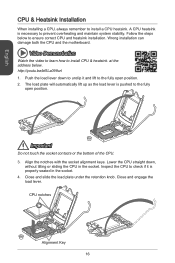
...://youtu.be/bf5La099urI 1. Important Do not touch the socket contacts or the bottom of the CPU. 3. Wrong installation can damage both the CPU and the motherboard. Push the load lever down , without tilting or sliding the CPU in the socket. 4. English CPU & Heatsink Installation When installing a CPU, always remember to ensure...
...://youtu.be/bf5La099urI 1. Important Do not touch the socket contacts or the bottom of the CPU. 3. Wrong installation can damage both the CPU and the motherboard. Push the load lever down , without tilting or sliding the CPU in the socket. 4. English CPU & Heatsink Installation When installing a CPU, always remember to ensure...
User Guide
Page 17
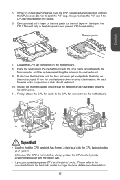
...be heard. 10. Press the four fasteners down the load lever the PnP cap will help in place. 11. Place the heatsink on the motherboard. 9. Important • Confirm that the fastener-ends have been properly locked in heat dissipation and prevent CPU overheating. Always replace the PnP ...press down to the documentation in the heatsink/ cooler package for more details about installation. 17 As each fastener locks into the holes on the motherboard. Finally, attach the CPU fan cable to ensure that the CPU heatsink has formed a tight seal with the CPU before booting your system....
...be heard. 10. Press the four fasteners down the load lever the PnP cap will help in place. 11. Place the heatsink on the motherboard. 9. Important • Confirm that the fastener-ends have been properly locked in heat dissipation and prevent CPU overheating. Always replace the PnP ...press down to the documentation in the heatsink/ cooler package for more details about installation. 17 As each fastener locks into the holes on the motherboard. Finally, attach the CPU fan cable to ensure that the CPU heatsink has formed a tight seal with the CPU before booting your system....
User Guide
Page 19
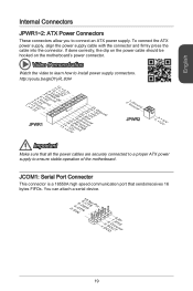
... speed communication port that all the power cables are securely connected to a proper ATX power supply to ensure stable operation of the motherboard. If done correctly, the clip on the motherboard's power connector. Video Demonstration Watch the video to learn how to connect an ATX power supply. English Internal Connectors JPWR1~2: ATX...
... speed communication port that all the power cables are securely connected to a proper ATX power supply to ensure stable operation of the motherboard. If done correctly, the clip on the motherboard's power connector. Video Demonstration Watch the video to learn how to connect an ATX power supply. English Internal Connectors JPWR1~2: ATX...
User Guide
Page 20
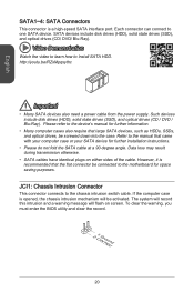
... a power cable from the power supply. Data loss may result during transmission otherwise. • SATA cables have identical plugs on screen. Please refer to the motherboard for further installation instructions. • Please do not fold the SATA cable at a 90-degree angle. If the computer case is a high-speed SATA interface...
... a power cable from the power supply. Data loss may result during transmission otherwise. • SATA cables have identical plugs on screen. Please refer to the motherboard for further installation instructions. • Please do not fold the SATA cable at a 90-degree angle. If the computer case is a high-speed SATA interface...
User Guide
Page 21
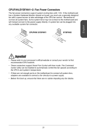
... will instead connect to find recommended CPU heatsink. • These connectors support Smart Fan Control with liner mode. If the motherboard has a System Hardware Monitor chipset on the motherboard to connect all system fans. Remember to connect all system fans, adapters are available to connect a fan directly to take advantage of the...
... will instead connect to find recommended CPU heatsink. • These connectors support Smart Fan Control with liner mode. If the motherboard has a System Hardware Monitor chipset on the motherboard to connect all system fans. Remember to connect all system fans, adapters are available to connect a fan directly to take advantage of the...
User Guide
Page 22
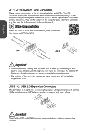
... learn how to determine correct connector orientation and placement. • The majority of the computer case's front panel connectors will primarily be plugged into the motherboard. Please use the optional M-Connector to simplify installation. English JFP1, JFP2: System Panel Connectors These connectors connect to avoid possible damage. 22 Plug all the...
... learn how to determine correct connector orientation and placement. • The majority of the computer case's front panel connectors will primarily be plugged into the motherboard. Please use the optional M-Connector to simplify installation. English JFP1, JFP2: System Panel Connectors These connectors connect to avoid possible damage. 22 Plug all the...
User Guide
Page 24
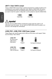
... to clear the CMOS RAM. 1 Keep Data 1 Clear Data Important You can automatically boot into the operating system (OS) every time it will damage the motherboard. Afterwards, open the jumper . Do not clear the CMOS RAM while the system is external powered from a battery located on the... motherboard to assign which USB and PS/2 ports could support "Wake Up Event Setup" field of BIOS. English JBAT1: Clear CMOS Jumper There is CMOS RAM ...
... to clear the CMOS RAM. 1 Keep Data 1 Clear Data Important You can automatically boot into the operating system (OS) every time it will damage the motherboard. Afterwards, open the jumper . Do not clear the CMOS RAM while the system is external powered from a battery located on the... motherboard to assign which USB and PS/2 ports could support "Wake Up Event Setup" field of BIOS. English JBAT1: Clear CMOS Jumper There is CMOS RAM ...
User Guide
Page 26
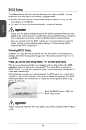
...8226; Please load the default settings to enter the BIOS setup. You may need to enter BIOS, restart the system by simultaneously pressing , , and keys. MSI additionally provides two methods to restore the optimal system performance and stability if the system becomes unstable after changing BIOS settings. Select the "Restore Defaults... When the message below appears on the computer and the system will start the Power On Self Test (POST) process. Click "GO2BIOS" tab on the motherboard to enable the system going to enter the BIOS setup. 26 You can click the "GO2BIOS" tab on...
...8226; Please load the default settings to enter the BIOS setup. You may need to enter BIOS, restart the system by simultaneously pressing , , and keys. MSI additionally provides two methods to restore the optimal system performance and stability if the system becomes unstable after changing BIOS settings. Select the "Restore Defaults... When the message below appears on the computer and the system will start the Power On Self Test (POST) process. Click "GO2BIOS" tab on the motherboard to enable the system going to enter the BIOS setup. 26 You can click the "GO2BIOS" tab on...


