User Manual
Page 3
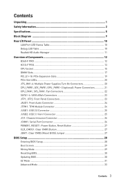
...Rear I/O Panel ...10 LAN Port LED Status Table 10 Debug LED Table 10 Realtek HD Audio Manager 11 Overview of Components 12 B360-F PRO ...12 H310-F PRO ...13 CPU Socket ...15 DIMM Slots...17 PCI_E1~18: PCIe Expansion Slots 19 PCIe Slot LEDs...20 JPS_ON1~4: Multiple Power Supplies Turn ...: Serial Port Connector 26 POWER1, RESET1: Power Button, Reset Button 27 CLR_CMOS1: Clear CMOS Button 27 JBAT1: Clear CMOS (Reset BIOS) Jumper 27 BIOS Setup ...28 Entering BIOS Setup 28 Boot Screen ...29 Mining Mode ...29 Resetting BIOS...30 Updating BIOS...30 EZ Mode ...31 Advanced Mode ...33 Contents 3
...Rear I/O Panel ...10 LAN Port LED Status Table 10 Debug LED Table 10 Realtek HD Audio Manager 11 Overview of Components 12 B360-F PRO ...12 H310-F PRO ...13 CPU Socket ...15 DIMM Slots...17 PCI_E1~18: PCIe Expansion Slots 19 PCIe Slot LEDs...20 JPS_ON1~4: Multiple Power Supplies Turn ...: Serial Port Connector 26 POWER1, RESET1: Power Button, Reset Button 27 CLR_CMOS1: Clear CMOS Button 27 JBAT1: Clear CMOS (Reset BIOS) Jumper 27 BIOS Setup ...28 Entering BIOS Setup 28 Boot Screen ...29 Mining Mode ...29 Resetting BIOS...30 Updating BIOS...30 EZ Mode ...31 Advanced Mode ...33 Contents 3

User Manual
Page 7
Form Factor BIOS Features Software Continued from previous page y ATX Form Factor y 12.0 in . (30.5 cm x 22.5 cm) y 1x 128 Mb flash y UEFI AMI BIOS y ACPI 6.1, SMBIOS 2.8 y Multi-language y Drivers y APP MANAGER y COMMAND CENTER y LIVE UPDATE 6 y SMART TOOL y RAMDISK y DPC LATENCY TUNER y FAST BOOT y X-BOOST y SUPER CHARGER y NETWORK MANAGER y CPU-Z MSI GAMING y Intel® Extreme Tuning Utility y Google Chrome™ ,Google Toolbar, Google Drive y Norton™ Internet Security Solution Continued on next page Specifications 7 x 8.9 in .
Form Factor BIOS Features Software Continued from previous page y ATX Form Factor y 12.0 in . (30.5 cm x 22.5 cm) y 1x 128 Mb flash y UEFI AMI BIOS y ACPI 6.1, SMBIOS 2.8 y Multi-language y Drivers y APP MANAGER y COMMAND CENTER y LIVE UPDATE 6 y SMART TOOL y RAMDISK y DPC LATENCY TUNER y FAST BOOT y X-BOOST y SUPER CHARGER y NETWORK MANAGER y CPU-Z MSI GAMING y Intel® Extreme Tuning Utility y Google Chrome™ ,Google Toolbar, Google Drive y Norton™ Internet Security Solution Continued on next page Specifications 7 x 8.9 in .

User Manual
Page 8
Special Features Continued from previous page y Audio ƒ Audio Boost y Network ƒ Intel LAN with Network Manager y Fan ƒ Smart Fan Control y LED ƒ EZ DEBUG LED y Stability ƒ 7000+ Quality Test y VR ƒ VR Ready y BIOS ƒ Click BIOS 5 8 Specifications
Special Features Continued from previous page y Audio ƒ Audio Boost y Network ƒ Intel LAN with Network Manager y Fan ƒ Smart Fan Control y LED ƒ EZ DEBUG LED y Stability ƒ 7000+ Quality Test y VR ƒ VR Ready y BIOS ƒ Click BIOS 5 8 Specifications

User Manual
Page 14
... PCI_E1~18 POWER1, RESET1 SATA1~4 Port Type Clear CMOS Button Fan Connectors Power Connectors LGA1151 CPU Socket DIMM Slots Front Audio Connector Clear CMOS (Reset BIOS) Jumper Chassis Intrusion Connector Serial Port Connector Front Panel Connectors Multiple Power Supplies Turn On Connectors TPM Module Connector USB 2.0 Connector USB 3.1 Gen1 Connector PCIe...
... PCI_E1~18 POWER1, RESET1 SATA1~4 Port Type Clear CMOS Button Fan Connectors Power Connectors LGA1151 CPU Socket DIMM Slots Front Audio Connector Clear CMOS (Reset BIOS) Jumper Chassis Intrusion Connector Serial Port Connector Front Panel Connectors Multiple Power Supplies Turn On Connectors TPM Module Connector USB 2.0 Connector USB 3.1 Gen1 Connector PCIe...

User Manual
Page 17
... addressable memory is 4GB or less for full DIMMs installation or overclocking. y Based on the motherboard. to set the memory frequency if you want to BIOS and find the Memory Try It! Therefore, we recommended that the maximum capacity of installed memory module depend on its Serial Presence Detect (SPD). y Due...
... addressable memory is 4GB or less for full DIMMs installation or overclocking. y Based on the motherboard. to set the memory frequency if you want to BIOS and find the Memory Try It! Therefore, we recommended that the maximum capacity of installed memory module depend on its Serial Presence Detect (SPD). y Due...

User Manual
Page 22
CPU_FAN1, SYS_FAN1: Fan Connectors Fan connectors can switch between PWM mode and DC mode and adjust fan speed in BIOS > HARDWARE MONITOR. Select PWM mode or DC mode There are working properly after switching the PWM/ DC mode. Pin definition of fan connectors PWM Mode ...
CPU_FAN1, SYS_FAN1: Fan Connectors Fan connectors can switch between PWM mode and DC mode and adjust fan speed in BIOS > HARDWARE MONITOR. Select PWM mode or DC mode There are working properly after switching the PWM/ DC mode. Pin definition of fan connectors PWM Mode ...

User Manual
Page 26
... select Yes. Set Chassis Intrusion to connect the chassis intrusion switch cable. Go to the chassis intrusion switch/ sensor on . Connect the JCI1 connector to BIOS > Settings > Security > Chassis Intrusion Configuration. 2. Close the chassis cover. 3. Go to select Yes. 6. Press F10 to save and exit and then ...screen when the computer is turned on the chassis. 2. Press F10 to save and exit and then press the Enter key to BIOS > Settings > Security > Chassis Intrusion Configuration. 4. Set Chassis Intrusion to Reset. 3. Resetting the chassis intrusion warning 1.
... select Yes. Set Chassis Intrusion to connect the chassis intrusion switch cable. Go to the chassis intrusion switch/ sensor on . Connect the JCI1 connector to BIOS > Settings > Security > Chassis Intrusion Configuration. 2. Close the chassis cover. 3. Go to select Yes. 6. Press F10 to save and exit and then ...screen when the computer is turned on the chassis. 2. Press F10 to save and exit and then press the Enter key to BIOS > Settings > Security > Chassis Intrusion Configuration. 4. Set Chassis Intrusion to Reset. 3. Resetting the chassis intrusion warning 1.

User Manual
Page 27
...power on the motherboard to save system configuration data. If you to power on / reset the computer. Keep Data (default) Clear CMOS/ Reset BIOS Resetting BIOS to default values 1. Use a jumper cap to short JBAT1 for about 5-10 seconds. 3. Press and hold the Clear CMOS button for about... 5-10 seconds to reset BIOS to default values. Remove the jumper cap from a battery located on the computer. POWER1, RESET1: Power Button, Reset Button The Power / Reset ...
...power on the motherboard to save system configuration data. If you to power on / reset the computer. Keep Data (default) Clear CMOS/ Reset BIOS Resetting BIOS to default values 1. Use a jumper cap to short JBAT1 for about 5-10 seconds. 3. Press and hold the Clear CMOS button for about... 5-10 seconds to reset BIOS to default values. Remove the jumper cap from a battery located on the computer. POWER1, RESET1: Power Button, Reset Button The Power / Reset ...
User Manual
Page 28
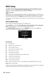
... MSI FAST BOOT application. BIOS Setup The default settings offer the optimal performance for reference only. You should be for system stability in this chapter are familiar with BIOS. y Press Delete key, when the Press DEL key to enter Setup Menu, F11 to the HELP information panel for BIOS ...may be slightly different from the product you press F10, a confirmation window appears and it to confirm your choice. 28 BIOS Setup Entering BIOS Setup Please refer the following methods to avoid possible system damage or failure booting unless you are for better system performance....
... MSI FAST BOOT application. BIOS Setup The default settings offer the optimal performance for reference only. You should be for system stability in this chapter are familiar with BIOS. y Press Delete key, when the Press DEL key to enter Setup Menu, F11 to the HELP information panel for BIOS ...may be slightly different from the product you press F10, a confirmation window appears and it to confirm your choice. 28 BIOS Setup Entering BIOS Setup Please refer the following methods to avoid possible system damage or failure booting unless you are for better system performance....

User Manual
Page 29
... will appear on the screen. y Mining Mode Indicator - describes the available hotkeys. Del key: Enter BIOS setup. F11: Enter boot menu for 5 seconds. Advanced Mode Switch Mining Mode ON/OFF BIOS Setup 29 y Motherboard Name - shows whether Mining Mode is Mining Mode ON and you do not need...+M: Switch between Mining Mode and Standard Mode. Ctrl+F5: Enter M-Flash mode to change any settings for the mining system. Mining Mode The BIOS default setting is ON or OFF. Motherboard Name GPU Status Mining Mode Indicator Hotkey Description y GPU Status - Red slot: The slot is empty...
... will appear on the screen. y Mining Mode Indicator - describes the available hotkeys. Del key: Enter BIOS setup. F11: Enter boot menu for 5 seconds. Advanced Mode Switch Mining Mode ON/OFF BIOS Setup 29 y Motherboard Name - shows whether Mining Mode is Mining Mode ON and you do not need...+M: Switch between Mining Mode and Standard Mode. Ctrl+F5: Enter M-Flash mode to change any settings for the mining system. Mining Mode The BIOS default setting is ON or OFF. Motherboard Name GPU Status Mining Mode Indicator Hotkey Description y GPU Status - Red slot: The slot is empty...
User Manual
Page 30
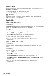
... choose In Windows mode. Select a BIOS file to the Clear CMOS jumper section for resetting BIOS. Updating BIOS: 1. Click on Yes to download and install the latest BIOS file. 5. Insert the USB flash drive that matches your motherboard model from MSI website. Click on Download icon to ...reboot the system and enter the flash mode. 4. Select BIOS Update. 3. And then save the BIOS file into the computer. 2. Click on the motherboard. After the flashing process is set properly. Install and launch MSI LIVE UPDATE 6. 2. y Short the Clear CMOS jumper on Scan button...
... choose In Windows mode. Select a BIOS file to the Clear CMOS jumper section for resetting BIOS. Updating BIOS: 1. Click on Yes to download and install the latest BIOS file. 5. Insert the USB flash drive that matches your motherboard model from MSI website. Click on Download icon to ...reboot the system and enter the flash mode. 4. Select BIOS Update. 3. And then save the BIOS file into the computer. 2. Click on the motherboard. After the flashing process is set properly. Install and launch MSI LIVE UPDATE 6. 2. y Short the Clear CMOS jumper on Scan button...

User Manual
Page 31
...memory module is left to right. Move the mouse over a blank space and right click the mouse to switch between Advanced mode and EZ mode. BIOS Setup 31 profile. This switch will show. y Language - click on the inner circle to USB flash drive (FAT/ FAT32 format only). allows you... you to configure the basic setting. click on this tab or the F7 key to exit search page. To configure the advanced BIOS settings, please enter the Advanced Mode by BIOS item name, enter the item name to find the item listing. Switch the outer circle to select the X.M.P. y Search -...
...memory module is left to right. Move the mouse over a blank space and right click the mouse to switch between Advanced mode and EZ mode. BIOS Setup 31 profile. This switch will show. y Language - click on the inner circle to USB flash drive (FAT/ FAT32 format only). allows you... you to configure the basic setting. click on this tab or the F7 key to exit search page. To configure the advanced BIOS settings, please enter the Advanced Mode by BIOS item name, enter the item name to find the item listing. Switch the outer circle to select the X.M.P. y Search -...

User Manual
Page 32
... key to a favorite page (Favorite 1~5) 1. Move the mouse over a BIOS item on search page. 2. Move the mouse over a BIOS item not only on BIOS menu but also on favorite page (Favorite 1~5) 2. It allows you to create personal BIOS menu where you to update BIOS with a USB flash drive. Right-click or press F2 key... (e.g. enable or disable the Mining Mode, Fast Boot, LAN Option ROM, AHCI Activated, CPU Fan Fail Warning Control and BIOS Log Review by percentage. click on the CPU, Memory, Storage, Fan Info and Help buttons on this button to display the M-Flash menu that allows...
... key to a favorite page (Favorite 1~5) 1. Move the mouse over a BIOS item on search page. 2. Move the mouse over a BIOS item not only on BIOS menu but also on favorite page (Favorite 1~5) 2. It allows you to create personal BIOS menu where you to update BIOS with a USB flash drive. Right-click or press F2 key... (e.g. enable or disable the Mining Mode, Fast Boot, LAN Option ROM, AHCI Activated, CPU Fan Fail Warning Control and BIOS Log Review by percentage. click on the CPU, Memory, Storage, Fan Info and Help buttons on this button to display the M-Flash menu that allows...

User Manual
Page 33
... of system. ƒ BOARD EXPLORER - allows you to specify the parameters for chipset and boot devices. ƒ OC - y Menu display - BIOS Setup 33 the following options are available: ƒ SETTINGS - allows you to manage overclocking profiles. ƒ HARDWARE MONITOR - Advanced Mode Press Setup ...Mode switch or F7 function key can switch between EZ Mode and Advanced Mode in BIOS setup. provides the way to the descriptions of installed devices on this motherboard. allows you to be configured. provides the information of...
... of system. ƒ BOARD EXPLORER - allows you to specify the parameters for chipset and boot devices. ƒ OC - y Menu display - BIOS Setup 33 the following options are available: ƒ SETTINGS - allows you to manage overclocking profiles. ƒ HARDWARE MONITOR - Advanced Mode Press Setup ...Mode switch or F7 function key can switch between EZ Mode and Advanced Mode in BIOS setup. provides the way to the descriptions of installed devices on this motherboard. allows you to be configured. provides the information of...

User Manual
Page 34
... the information of the device and motherboard. f DMI Information Shows system information, desktop Board Information and chassis Information. (Read only). 34 BIOS Setup The time format is . Important If the connected SATA device is not displayed, turn off computer and re-check SATA cable and...Day of the week, from Sun to Standard Mode. through Dec. Read-only. SETTINGS f Mining Mode [Enabled] When Enabled, the BIOS will automatically set mining system related parameters. [Enabled] Change the parameters to Mining Mode. [Disabled] Change the parameters to Sat, determined by users...
... the information of the device and motherboard. f DMI Information Shows system information, desktop Board Information and chassis Information. (Read only). 34 BIOS Setup The time format is . Important If the connected SATA device is not displayed, turn off computer and re-check SATA cable and...Day of the week, from Sun to Standard Mode. through Dec. Read-only. SETTINGS f Mining Mode [Enabled] When Enabled, the BIOS will automatically set mining system related parameters. [Enabled] Change the parameters to Mining Mode. [Disabled] Change the parameters to Sat, determined by users...
User Manual
Page 35
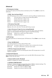
...CPU overheating alert when CPU temperature is only available if the system supports 64-bit PCI decoding. [Enabled] Allows you to be configured automatically by BIOS. [Gen1] Enables PCIe Gen1 support only. [Gen2] Enables PCIe Gen2 support only. [Gen3] Enables PCIe Gen3 support only. f Integrated Peripherals Sets...80 degrees centigrade. fPCI Latency Timer [32] Sets latency timer of onboard power LED behaviors. Press Enter to indicate the S3 state. BIOS Setup 35 Press Enter to enter the sub-menu. Press Enter to enter the sub-menu. This item will be decoded in above ...
...CPU overheating alert when CPU temperature is only available if the system supports 64-bit PCI decoding. [Enabled] Allows you to be configured automatically by BIOS. [Gen1] Enables PCIe Gen1 support only. [Gen2] Enables PCIe Gen2 support only. [Gen3] Enables PCIe Gen3 support only. f Integrated Peripherals Sets...80 degrees centigrade. fPCI Latency Timer [32] Sets latency timer of onboard power LED behaviors. Press Enter to indicate the S3 state. BIOS Setup 35 Press Enter to enter the sub-menu. Press Enter to enter the sub-menu. This item will be decoded in above ...

User Manual
Page 36
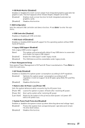
... settings for the SATA ports. fIpv6 PXE Support [Enabled] When Enabled, the system UEFI network stack will appear when IGD Multi-Monitor is enabled. 36 BIOS Setup fSATA Mode [AHCI Mode] Sets the operation mode of system memory allocated to enable or disable the SATA hot plug support. [Enabled] Enables hot...
... settings for the SATA ports. fIpv6 PXE Support [Enabled] When Enabled, the system UEFI network stack will appear when IGD Multi-Monitor is enabled. 36 BIOS Setup fSATA Mode [AHCI Mode] Sets the operation mode of system memory allocated to enable or disable the SATA hot plug support. [Enabled] Enables hot...
User Manual
Page 37
... Off] Leaves the system in power off ) before AC power loss. f Power Management Setup Sets system Power Management of ErP and AC Power Loss behaviors. BIOS Setup 37 Press Enter to the previous state (power on/ power off state after restoring AC power. [Last State] Restores the system to enter the...
... Off] Leaves the system in power off ) before AC power loss. f Power Management Setup Sets system Power Management of ErP and AC Power Loss behaviors. BIOS Setup 37 Press Enter to the previous state (power on/ power off state after restoring AC power. [Last State] Restores the system to enter the...
User Manual
Page 38
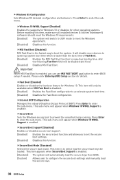
...booting time. It will appear when Windows 10 WHQL Support is faster than the boot time of Fast Boot. [Enabled] Enables the MSI Fast Boot function to enter BIOS setup if needed. fFast Boot [Enabled] Enables or disables the fast boot feature for details. This item appears when Secure Boot ... secure keys from BIOS. [Custom] Allows user to meet the Windows equirement. [Disabled] Disables this function. This item will appear when Windows 10 WHQL Support is the fastest way to enter the submenu. Press Enter to select how the secure boot keys be available when MSI Fast Boot is ...
...booting time. It will appear when Windows 10 WHQL Support is faster than the boot time of Fast Boot. [Enabled] Enables the MSI Fast Boot function to enter BIOS setup if needed. fFast Boot [Enabled] Enables or disables the fast boot feature for details. This item appears when Secure Boot ... secure keys from BIOS. [Custom] Allows user to meet the Windows equirement. [Disabled] Disables this function. This item will appear when Windows 10 WHQL Support is the fastest way to enter the submenu. Press Enter to select how the secure boot keys be available when MSI Fast Boot is ...
User Manual
Page 39
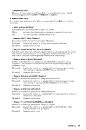
... mouse. [Enabled] Enables the system to be awakened from sleep state when activity of PCIe device is detected. [Disabled] Disables this function. BIOS Setup 39 f Wake Up Event Setup Sets system wake up ) on a scheduled time/ date. [Disabled] Disables this function. fResume by USB... function. This submenu will automatically resume (boot up behaviors for different sleep modes. fWake Up Event By [BIOS] Selects the wake up event by BIOS or operating system. [BIOS] Activates the following items, set to [Enabled], the system will appear when Secure Boot Mode sets to ...
... mouse. [Enabled] Enables the system to be awakened from sleep state when activity of PCIe device is detected. [Disabled] Disables this function. BIOS Setup 39 f Wake Up Event Setup Sets system wake up ) on a scheduled time/ date. [Disabled] Disables this function. fResume by USB... function. This submenu will automatically resume (boot up behaviors for different sleep modes. fWake Up Event By [BIOS] Selects the wake up event by BIOS or operating system. [BIOS] Activates the following items, set to [Enabled], the system will appear when Secure Boot Mode sets to ...


