User Manual
Page 3
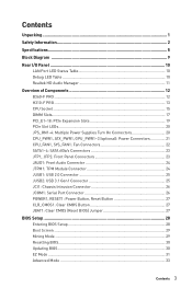
... Slots 19 PCIe Slot LEDs...20 JPS_ON1~4: Multiple Power Supplies Turn On Connectors 20 CPU_PWR1, ATX_PWR1, GPU_PWR1~3 (optional): Power Connectors 21 CPU_FAN1, SYS_FAN1: Fan Connectors 22 SATA1~4: SATA 6Gb/s Connectors 23 JFP1, JFP2: Front Panel Connectors 23 JAUD1: Front Audio Connector 24 JTPM1: TPM Module Connector 24 JUSB1: USB 2.0 Connector 25 JUSB2: USB 3.1 Gen1 Connector 25 JCI1: Chassis Intrusion Connector 26 JCOM1: Serial Port Connector 26 POWER1, RESET1: Power Button, Reset Button 27 CLR_CMOS1: Clear CMOS Button 27 JBAT1: Clear CMOS (Reset BIOS) Jumper 27 BIOS Setup...
... Slots 19 PCIe Slot LEDs...20 JPS_ON1~4: Multiple Power Supplies Turn On Connectors 20 CPU_PWR1, ATX_PWR1, GPU_PWR1~3 (optional): Power Connectors 21 CPU_FAN1, SYS_FAN1: Fan Connectors 22 SATA1~4: SATA 6Gb/s Connectors 23 JFP1, JFP2: Front Panel Connectors 23 JAUD1: Front Audio Connector 24 JTPM1: TPM Module Connector 24 JUSB1: USB 2.0 Connector 25 JUSB2: USB 3.1 Gen1 Connector 25 JCI1: Chassis Intrusion Connector 26 JCOM1: Serial Port Connector 26 POWER1, RESET1: Power Button, Reset Button 27 CLR_CMOS1: Clear CMOS Button 27 JBAT1: Clear CMOS (Reset BIOS) Jumper 27 BIOS Setup...

User Manual
Page 6
...2x 4-pin PCIe power connectors(H310-F PRO) y 4x 2-pin PS_ON connectors y 4x SATA 6Gb/s connectors y 1x USB 3.1 Gen1 connector (supports additional 2 USB 3.1 Gen1 ports) y 1x USB 2.0 connector (supports additional 2 USB 2.0 ports) y 1x 4-pin CPU fan connector y 1x 4-pin system fan connector y 1x Front panel audio connector y 2x Front panel connectors y 1x TPM module connector y 1x Chassis Intrusion connector y 1x Serial port connector y 1x Clear CMOS jumper y 1x Power button y 1x Reset button y 1x Clear CMOS button I/O Controller NUVOTON NCT5567 Controller Chip Hardware Monitor...
...2x 4-pin PCIe power connectors(H310-F PRO) y 4x 2-pin PS_ON connectors y 4x SATA 6Gb/s connectors y 1x USB 3.1 Gen1 connector (supports additional 2 USB 3.1 Gen1 ports) y 1x USB 2.0 connector (supports additional 2 USB 2.0 ports) y 1x 4-pin CPU fan connector y 1x 4-pin system fan connector y 1x Front panel audio connector y 2x Front panel connectors y 1x TPM module connector y 1x Chassis Intrusion connector y 1x Serial port connector y 1x Clear CMOS jumper y 1x Power button y 1x Reset button y 1x Clear CMOS button I/O Controller NUVOTON NCT5567 Controller Chip Hardware Monitor...

User Manual
Page 15
... motherboard. y This motherboard is the Pin 1 indicator. CPU Socket Distance from the power outlet before booting your system. The golden triangle is designed to prevent overheating and maintain system stability. y Whenever the CPU is not installed, always protect the CPU socket pins by inadequate operation beyond product specifications is necessary to support overclocking. Overview of thermal paste (or thermal tape) between the CPU and the heatsink to install a CPU heatsink...
... motherboard. y This motherboard is the Pin 1 indicator. CPU Socket Distance from the power outlet before booting your system. The golden triangle is designed to prevent overheating and maintain system stability. y Whenever the CPU is not installed, always protect the CPU socket pins by inadequate operation beyond product specifications is necessary to support overclocking. Overview of thermal paste (or thermal tape) between the CPU and the heatsink to install a CPU heatsink...
User Manual
Page 30
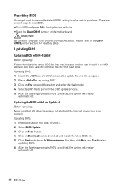
... BIOS file. 5. y Short the Clear CMOS jumper on Scan button. 4. Resetting BIOS You might need to restore the default BIOS setting to solve certain problems. There are several ways to reset BIOS: y Go to BIOS and press F6 to the Clear CMOS jumper section for resetting BIOS. Please refer to load optimized defaults. Updating BIOS Updating BIOS with Live Update 6 Before updating: Make sure the LAN driver is already installed and the Internet connection is off before clearing CMOS data. Click Next and choose In Windows mode...
... BIOS file. 5. y Short the Clear CMOS jumper on Scan button. 4. Resetting BIOS You might need to restore the default BIOS setting to solve certain problems. There are several ways to reset BIOS: y Go to BIOS and press F6 to the Clear CMOS jumper section for resetting BIOS. Please refer to load optimized defaults. Updating BIOS Updating BIOS with Live Update 6 Before updating: Make sure the LAN driver is already installed and the Internet connection is off before clearing CMOS data. Click Next and choose In Windows mode...

User Manual
Page 31
... of BIOS setup. To configure the advanced BIOS settings, please enter the Advanced Mode by BIOS item name, enter the item name to exit search page. This switch will show. click on the inner circle to enable/ disable the X.M.P. (Extreme Memory Profile). y Language - y System information - profile. you to change the boot priority. XMP switch Setup Mode switch Screenshot Search Language System information Information display M-Flash Favorites Hardware Monitor Boot device priority bar Function buttons y XMP switch...
... of BIOS setup. To configure the advanced BIOS settings, please enter the Advanced Mode by BIOS item name, enter the item name to exit search page. This switch will show. click on the inner circle to enable/ disable the X.M.P. (Extreme Memory Profile). y Language - y System information - profile. you to change the boot priority. XMP switch Setup Mode switch Screenshot Search Language System information Information display M-Flash Favorites Hardware Monitor Boot device priority bar Function buttons y XMP switch...

User Manual
Page 32
... a USB flash drive. click on the CPU, Memory, Storage, Fan Info and Help buttons on OK. ƒ To delete a BIOS item from favorite page 1. SETTINGS, OC...,etc) as the BIOS home page. ƒ Favorite1~5 - Right-click or press F2 key. 3. y Function buttons - enable or disable the Mining Mode, Fast Boot, LAN Option ROM, AHCI Activated, CPU Fan Fail Warning Control and BIOS Log Review by percentage. y Hardware Monitor - click on search page. 2. allows you can save and access...
... a USB flash drive. click on the CPU, Memory, Storage, Fan Info and Help buttons on OK. ƒ To delete a BIOS item from favorite page 1. SETTINGS, OC...,etc) as the BIOS home page. ƒ Favorite1~5 - Right-click or press F2 key. 3. y Function buttons - enable or disable the Mining Mode, Fast Boot, LAN Option ROM, AHCI Activated, CPU Fan Fail Warning Control and BIOS Log Review by percentage. y Hardware Monitor - click on search page. 2. allows you can save and access...

User Manual
Page 33
... MONITOR - provides the way to be configured. provides the information of EZ Mode Overview section. BIOS Setup 33 provides BIOS setting items and information to update BIOS with a USB flash drive. ƒ OC PROFILE - allows you to the descriptions of installed devices on this motherboard. y Menu display - the following options are available: ƒ SETTINGS - Increasing the frequency may get better performance. ƒ M-FLASH - y BIOS menu selection - XMP switch Setup Mode switch Screenshot Search Language System information Boot device priority...
... MONITOR - provides the way to be configured. provides the information of EZ Mode Overview section. BIOS Setup 33 provides BIOS setting items and information to update BIOS with a USB flash drive. ƒ OC PROFILE - allows you to the descriptions of installed devices on this motherboard. y Menu display - the following options are available: ƒ SETTINGS - Increasing the frequency may get better performance. ƒ M-FLASH - y BIOS menu selection - XMP switch Setup Mode switch Screenshot Search Language System information Boot device priority...
User Manual
Page 35
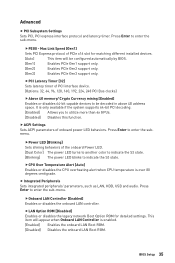
... as LAN, HDD, USB and audio. fPCI Latency Timer [32] Sets latency timer of onboard power LED behaviors. fLAN Option ROM [Disabled] Enables or disables the legacy network Boot Option ROM for matching different installed devices. [Auto] This item will appear when Onboard LAN Controller is over 80 degrees centigrade. Press Enter to utilize more than 4x GPUs. [Disabled] Disables this function. f ACPI Settings Sets ACPI parameters of PCI interface device. [Options: 32, 64, 96, 128, 160, 192, 224, 248 PCI Bus clocks] fAbove 4G memory/ Crypto Currency mining [Enabled] Enables...
... as LAN, HDD, USB and audio. fPCI Latency Timer [32] Sets latency timer of onboard power LED behaviors. fLAN Option ROM [Disabled] Enables or disables the legacy network Boot Option ROM for matching different installed devices. [Auto] This item will appear when Onboard LAN Controller is over 80 degrees centigrade. Press Enter to utilize more than 4x GPUs. [Disabled] Disables this function. f ACPI Settings Sets ACPI parameters of PCI interface device. [Options: 32, 64, 96, 128, 160, 192, 224, 248 PCI Bus clocks] fAbove 4G memory/ Crypto Currency mining [Enabled] Enables...

User Manual
Page 36
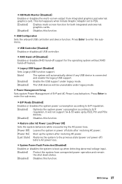
fHD Audio Controller [Enabled] Enables or disables the onboard High Definition Audio controller. Press Enter to enable or disable the SATA hot plug support. [Enabled] Enables hot plug support for the SATA ports. [Disabled] Disables hot plug support for SATA storage devices. fSATA Mode [AHCI Mode] Sets the operation mode of system memory allocated to enhance the speed and performance of SATA storage device, such as the primary boot device. [IGD] Integrated Graphics Display. [PEG] PCI-Express Graphics Device. AHCI (Advanced Host Controller Interface) offers some ...
fHD Audio Controller [Enabled] Enables or disables the onboard High Definition Audio controller. Press Enter to enable or disable the SATA hot plug support. [Enabled] Enables hot plug support for the SATA ports. [Disabled] Disables hot plug support for SATA storage devices. fSATA Mode [AHCI Mode] Sets the operation mode of system memory allocated to enhance the speed and performance of SATA storage device, such as the primary boot device. [IGD] Integrated Graphics Display. [PEG] PCI-Express Graphics Device. AHCI (Advanced Host Controller Interface) offers some ...
User Manual
Page 37
...Enables or disables the multi-screen output from unexpected power operation and remain the shut down status. [Disabled] Disables this function. Press Enter to enter the sub-menu. fLegacy USB Support [Enabled] Sets Legacy USB function support. [Auto] The system will automatically detect if any USB device is connected and enable the legacy USB support. [Enabled] Enable the USB support under legacy mode. [Disabled] The USB devices will not support S4 & S5 wake up when detecting abnormal voltage input. [Enabled] Protect the system from integrated graphics and external graphics card...
...Enables or disables the multi-screen output from unexpected power operation and remain the shut down status. [Disabled] Disables this function. Press Enter to enter the sub-menu. fLegacy USB Support [Enabled] Sets Legacy USB function support. [Auto] The system will automatically detect if any USB device is connected and enable the legacy USB support. [Enabled] Enable the USB support under legacy mode. [Disabled] The USB devices will not support S4 & S5 wake up when detecting abnormal voltage input. [Enabled] Protect the system from integrated graphics and external graphics card...
User Manual
Page 38
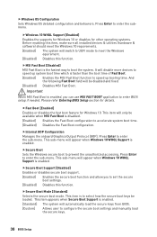
...all installed devices & utilities (hardware & software) should meet the Windows 10 requirements. [Enabled] The system will disable more devices to meet the Windows equirement. [Disabled] Disables this function. This sub-menu will automatically load the secure keys from BIOS. [Custom] Allows user to enter BIOS setup if needed. fSecure Boot Support [Disabled] Enables or disables secure boot support. [Enabled] Enables the secure boot function and allow you can use MSI FAST BOOT application to configure the secure boot settings and manually load the secure keys. 38 BIOS Setup...
...all installed devices & utilities (hardware & software) should meet the Windows 10 requirements. [Enabled] The system will disable more devices to meet the Windows equirement. [Disabled] Disables this function. This sub-menu will automatically load the secure keys from BIOS. [Custom] Allows user to enter BIOS setup if needed. fSecure Boot Support [Disabled] Enables or disables secure boot support. [Enabled] Enables the secure boot function and allow you can use MSI FAST BOOT application to configure the secure boot settings and manually load the secure keys. 38 BIOS Setup...
User Manual
Page 39
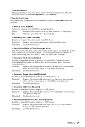
... Boot Mode sets to enter the sub-menu. fResume By PCI-E Device [Disabled] Enables or disables the wake up by third party integrated chips. [Enabled] Enables the system to be awakened from sleep state when activity of PS/2 mouse is detected. [Disabled] Disables this function. fResume From S3/S4/S5 by PS/2 Mouse [Disabled] Enables or disables the system wake up function of installed PCI-E expansion cards, integrated LAN controllers or USB devices which are supported by PS/2 mouse. [Enabled] Enables...
... Boot Mode sets to enter the sub-menu. fResume By PCI-E Device [Disabled] Enables or disables the wake up by third party integrated chips. [Enabled] Enables the system to be awakened from sleep state when activity of PS/2 mouse is detected. [Disabled] Disables this function. fResume From S3/S4/S5 by PS/2 Mouse [Disabled] Enables or disables the system wake up function of installed PCI-E expansion cards, integrated LAN controllers or USB devices which are supported by PS/2 mouse. [Enabled] Enables...

User Manual
Page 40
... Resume From S3/S4/S5 by BIOS when Windows 10 WHQL Support is enabled. [UEFI] [LEGACY+UEFI] Enables UEFI BIOS boot mode support only. f Intel ( R ) Ethernet Connection I219-V Shows driver information and configuration of Help information block. [Unlock] [Lock] Sliding effect. f GO2BIOS [Disabled] Allows system to enter BIOS setup directly by pressing the Power button for 4 sec pon bootup. [Enabled] [Disabled] The system boots straight to the BIOS setup by PS/2 keyboard. [Any Key] Enables the system to be erased...
... Resume From S3/S4/S5 by BIOS when Windows 10 WHQL Support is enabled. [UEFI] [LEGACY+UEFI] Enables UEFI BIOS boot mode support only. f Intel ( R ) Ethernet Connection I219-V Shows driver information and configuration of Help information block. [Unlock] [Lock] Sliding effect. f GO2BIOS [Disabled] Allows system to enter BIOS setup directly by pressing the Power button for 4 sec pon bootup. [Enabled] [Disabled] The system boots straight to the BIOS setup by PS/2 keyboard. [Any Key] Enables the system to be erased...
User Manual
Page 44
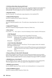
... graphics ratio. f Misc Setting* Press Enter, + or - fIntel Turbo Boost [Enabled]* Enables or disables the Intel® Turbo Boost. f Extreme Memory Profile (X.M.P.) [Disabled] X.M.P. (Extreme Memory Profile) is not guaranteed. f DRAM Reference Clock [Auto]* Sets the DRAM reference clock. Please note the overclocking behavior is the overclocking technology by memory module. Read-only. key to open or close the following 3 items related to adjust CPU voltage and core frequency dynamically. is installed. f Adjusted DRAM Frequency Shows the adjusted DRAM frequency...
... graphics ratio. f Misc Setting* Press Enter, + or - fIntel Turbo Boost [Enabled]* Enables or disables the Intel® Turbo Boost. f Extreme Memory Profile (X.M.P.) [Disabled] X.M.P. (Extreme Memory Profile) is not guaranteed. f DRAM Reference Clock [Auto]* Sets the DRAM reference clock. Please note the overclocking behavior is the overclocking technology by memory module. Read-only. key to open or close the following 3 items related to adjust CPU voltage and core frequency dynamically. is installed. f Adjusted DRAM Frequency Shows the adjusted DRAM frequency...
User Manual
Page 45
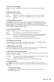
... replaced. [Enabled] [Disabled] The system will be configured automatically by choosing optimized memory preset. f CPU Specifications Press Enter to load the default settings.) f Memory Fast Boot [Auto]* Enables or disables the initiation and training for all memory channel. f DRAM Timing Mode [Link] Selects the memory timing mode. [Link] Allows user to configure the DRAM timing for memory. Disables this information menu at any time by pressing [F4]. This sub-menu displays the information of installed CPU. Read only. f CPU Memory Changed Detect [Enabled...
... replaced. [Enabled] [Disabled] The system will be configured automatically by choosing optimized memory preset. f CPU Specifications Press Enter to load the default settings.) f Memory Fast Boot [Auto]* Enables or disables the initiation and training for all memory channel. f DRAM Timing Mode [Link] Selects the memory timing mode. [Link] Allows user to configure the DRAM timing for memory. Disables this information menu at any time by pressing [F4]. This sub-menu displays the information of installed CPU. Read only. f CPU Memory Changed Detect [Enabled...
User Manual
Page 47
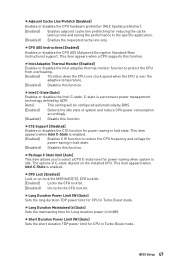
... the performance to protect the CPU from overheating. [Enabled] Throttles down the CPU core clock speed when the CPU is enabled. fCPU AES Instructions [Enabled] Enables or disables the CPU AES (Advanced Encryption Standard-New Instructions) support. fShort Duration Power Limit (W) [Auto] Sets the short duration TDP power limit for CPU in Turbo Boost mode. This item appears when a CPU supports this function. fC1E Support [Disabled] Enables or disables the C1E function for Long duration power Limit(W). This item appears...
... the performance to protect the CPU from overheating. [Enabled] Throttles down the CPU core clock speed when the CPU is enabled. fCPU AES Instructions [Enabled] Enables or disables the CPU AES (Advanced Encryption Standard-New Instructions) support. fShort Duration Power Limit (W) [Auto] Sets the short duration TDP power limit for CPU in Turbo Boost mode. This item appears when a CPU supports this function. fC1E Support [Disabled] Enables or disables the C1E function for Long duration power Limit(W). This item appears...
User Manual
Page 49
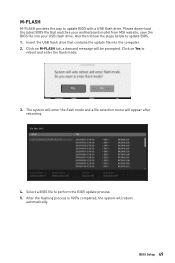
...% completed, the system will appear after rebooting. 4. Click on Yes to update BIOS with a USB flash drive. And then follow the steps below to perform the BIOS update process. 5. The system will enter the flash mode and a file selection menu will reboot automatically. M-FLASH M-FLASH provides the way to reboot and enter the flash mode. 3. Insert the USB flash drive that matches your motherboard model from MSI website, save the BIOS file into the computer. 2.
...% completed, the system will appear after rebooting. 4. Click on Yes to update BIOS with a USB flash drive. And then follow the steps below to perform the BIOS update process. 5. The system will enter the flash mode and a file selection menu will reboot automatically. M-FLASH M-FLASH provides the way to reboot and enter the flash mode. 3. Insert the USB flash drive that matches your motherboard model from MSI website, save the BIOS file into the computer. 2.

User Manual
Page 52
.... 7. Click Install button. 6. Click OK button to finish. 7. Press the Restart button on the screen to boot from the Boot Menu. 6. Power on the computer. 2. Insert MSI® Driver Disc into Boot Menu. 5. The installer will prompt you to restart. 6. Select the utilities you must complete drivers installation. 1. Software Description Please download and update the latest utilities and drivers at www.msi.com Installing Windows® 10 1. Press any key when screen shows Press any key to install Windows®...
.... 7. Click Install button. 6. Click OK button to finish. 7. Press the Restart button on the screen to boot from the Boot Menu. 6. Power on the computer. 2. Insert MSI® Driver Disc into Boot Menu. 5. The installer will prompt you to restart. 6. Select the utilities you must complete drivers installation. 1. Software Description Please download and update the latest utilities and drivers at www.msi.com Installing Windows® 10 1. Press any key when screen shows Press any key to install Windows®...

User Manual
Page 68
... over troubleshooting guide first to a electrical outlet securely. y Test with another known working graphics card. The power is turned on . y If 3 long beeps are connected from the power supply to audio ports on the motherboard rear IO panel. y Test with another known working y Make sure your TCP/IP settings. y Verify if USB device is no network y Make sure the network chipset driver has been installed. The computer does not boot after updating the BIOS y Clear the CMOS. The USB device is connected to install...
... over troubleshooting guide first to a electrical outlet securely. y Test with another known working graphics card. The power is turned on . y If 3 long beeps are connected from the power supply to audio ports on the motherboard rear IO panel. y Test with another known working y Make sure your TCP/IP settings. y Verify if USB device is no network y Make sure the network chipset driver has been installed. The computer does not boot after updating the BIOS y Clear the CMOS. The USB device is connected to install...
User Manual
Page 72
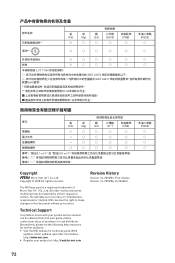
... respective owners. y Visit the MSI website for further guidance. The MSI logo used is expressed or implied. Copyright © 2018 All rights reserved. Technical Support If a problem arises with your system and no solution can be trademarks of Micro-Star Int'l Co., Ltd. Alternatively, please try the following help resources for technical guide, BIOS updates, driver updates, and other marks and...
... respective owners. y Visit the MSI website for further guidance. The MSI logo used is expressed or implied. Copyright © 2018 All rights reserved. Technical Support If a problem arises with your system and no solution can be trademarks of Micro-Star Int'l Co., Ltd. Alternatively, please try the following help resources for technical guide, BIOS updates, driver updates, and other marks and...


