

User Manual
Page 4
... interference to radio or television reception, which the receiver is eq uip men t h as been tested and found to operate the equipment. Micro-Star International MS-7241 This device complies with the limits for compliance could void the user's authority to comply with Part 15 of the FCC Rules.
... interference to radio or television reception, which the receiver is eq uip men t h as been tested and found to operate the equipment. Micro-Star International MS-7241 This device complies with the limits for compliance could void the user's authority to comply with Part 15 of the FCC Rules.

User Manual
Page 11
Getting Started Chapter 1 Getting Started Thank you for optimal system efficiency. The G965M/ Q965M/ Q963M Series mainboards are based on Intel® G965/ Q965/ Q963 & ICH8/ ICH8R chipsets for choosing the G965M/ Q965M/ Q963M Series (MS-7241 v1.X) Micro-ATX mainboard. Designed to fit the advanced Intel® CoreTM 2 Duo, Pentium 4, Pentium D and Celeron D processor, the G965M/ Q965M/ Q963M Series deliver a high performance and professional desktop platform solution. 1-1
Getting Started Chapter 1 Getting Started Thank you for optimal system efficiency. The G965M/ Q965M/ Q963M Series mainboards are based on Intel® G965/ Q965/ Q963 & ICH8/ ICH8R chipsets for choosing the G965M/ Q965M/ Q963M Series (MS-7241 v1.X) Micro-ATX mainboard. Designed to fit the advanced Intel® CoreTM 2 Duo, Pentium 4, Pentium D and Celeron D processor, the G965M/ Q965M/ Q963M Series deliver a high performance and professional desktop platform solution. 1-1

User Manual
Page 12
.../3/5/6) - 6 SATAII ports by ICH8R (SATA1~6) - Supports storage and data transfers at up to 8 GB, 240pin / 1.8V) For the updated supporting memory modules, please visit ht t p: / / w w w. MS-7241 Mainboard Mainboard Specifications Processor Support - Supports USB to 300 MB/s 1-2 p hp LAN - c om . For the latest information about CPU, please visit http://www...
.../3/5/6) - 6 SATAII ports by ICH8R (SATA1~6) - Supports storage and data transfers at up to 8 GB, 240pin / 1.8V) For the updated supporting memory modules, please visit ht t p: / / w w w. MS-7241 Mainboard Mainboard Specifications Processor Support - Supports USB to 300 MB/s 1-2 p hp LAN - c om . For the latest information about CPU, please visit http://www...
User Manual
Page 14
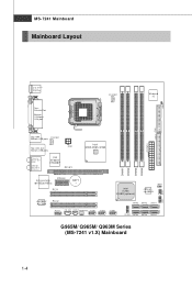
MS-7241 Mainboard Mainboard Layout J CA S E 1 DIMM1 DIMM2 DIMM3 DIMM4 JFP1 JFP2 Top : mouse Bo ttom: keyb oard Top : Parallel Port Bo tto m: COM port VGA port ... + Int e l ICH8/ ICH8R (optional) JMicron Jm20335 JBAT1 ALC883/ ALC888 PCI 2 J AU D 1 CD_IN1 JSPD1 PWRFAN1 JUSB1 JUSB2 JU SB 3 SATA5 SATA3 SATA1 JCOM 1 SATA6 SATA4 SATA2 G965M/ Q965M/ Q963M Series (MS-7241 v1.X) Mainboard 1-4
MS-7241 Mainboard Mainboard Layout J CA S E 1 DIMM1 DIMM2 DIMM3 DIMM4 JFP1 JFP2 Top : mouse Bo ttom: keyb oard Top : Parallel Port Bo tto m: COM port VGA port ... + Int e l ICH8/ ICH8R (optional) JMicron Jm20335 JBAT1 ALC883/ ALC888 PCI 2 J AU D 1 CD_IN1 JSPD1 PWRFAN1 JUSB1 JUSB2 JU SB 3 SATA5 SATA3 SATA1 JCOM 1 SATA6 SATA4 SATA2 G965M/ Q965M/ Q963M Series (MS-7241 v1.X) Mainboard 1-4

User Manual
Page 19
... (as the arrow shows). 3. The pins of your dealer to purchase and install them before installing the heat sink/ cooler fan for better heat dispersion. MS-7241 Mainboard CPU & Cooler Installation W hen you are installing the CPU, make sure the CPU has a cooler attached on CPU before turning on it to install...
... (as the arrow shows). 3. The pins of your dealer to purchase and install them before installing the heat sink/ cooler fan for better heat dispersion. MS-7241 Mainboard CPU & Cooler Installation W hen you are installing the CPU, make sure the CPU has a cooler attached on CPU before turning on it to install...

User Manual
Page 21
Turn over the mainboard to lock the h ook s . 12. Check the information in H/W M onitor in Figure 1) to fasten the cooler. MS-7241 Mainboard 9. Please note that the clip-ends are correctly inserted. Therefore we suggest you do not plug/unplug the CPU too often. 2-6 Push down the ...
Turn over the mainboard to lock the h ook s . 12. Check the information in H/W M onitor in Figure 1) to fasten the cooler. MS-7241 Mainboard 9. Please note that the clip-ends are correctly inserted. Therefore we suggest you do not plug/unplug the CPU too often. 2-6 Push down the ...

User Manual
Page 23
... center and will automatically close. DDRII modules are not interchangeable with DDR and the DDRII standard is properly inserted in different channel DDR DIMM slots. - MS-7241 Mainboard Installing DDRII Modules 1. Important You can barely see the golden finger if the module is not backwards compatible. The plastic clip at each side...
... center and will automatically close. DDRII modules are not interchangeable with DDR and the DDRII standard is properly inserted in different channel DDR DIMM slots. - MS-7241 Mainboard Installing DDRII Modules 1. Important You can barely see the golden finger if the module is not backwards compatible. The plastic clip at each side...

User Manual
Page 25
... Left Orange Green Right Orange LED State Off On (steady state) On (blinking) Off On On condition LAN link is for a PS/2® mouse/keyboard. MS-7241 Mainboard Back Panel Mouse Parallel Port IEEE1394 Port (optional) LAN L-In RS-Out Keyboard Serial Port VGA Port USB Ports L-Out CS-Out Mic SS...
... Left Orange Green Right Orange LED State Off On (steady state) On (blinking) Off On On condition LAN link is for a PS/2® mouse/keyboard. MS-7241 Mainboard Back Panel Mouse Parallel Port IEEE1394 Port (optional) LAN L-In RS-Out Keyboard Serial Port VGA Port USB Ports L-Out CS-Out Mic SS...

User Manual
Page 27
... mode by setting its jumper. We strongly recommend you must configure the second hard drive to IDE connector that supports Ultra DMA 66/ 100 function. MS-7241 Mainboard Connectors Floppy Disk Drive Connector: FDD1 This standard FDD connector supports 360K, 720K, 1.2M, 1.44M and 2.88M floppy disk types.
... mode by setting its jumper. We strongly recommend you must configure the second hard drive to IDE connector that supports Ultra DMA 66/ 100 function. MS-7241 Mainboard Connectors Floppy Disk Drive Connector: FDD1 This standard FDD connector supports 360K, 720K, 1.2M, 1.44M and 2.88M floppy disk types.

User Manual
Page 29
... audio. If the mainboard has a System Hardware Monitor chipset on-board, you must use a specially designed fan with +12V. W hen connecting the wire to GND. MS-7241 Mainboard Fan Power Connectors: CPUFAN1, SYSFAN1 & PWRFAN1 The fan power connectors support system cooling fan with speed sensor to take note that the red wire...
... audio. If the mainboard has a System Hardware Monitor chipset on-board, you must use a specially designed fan with +12V. W hen connecting the wire to GND. MS-7241 Mainboard Fan Power Connectors: CPUFAN1, SYSFAN1 & PWRFAN1 The fan power connectors support system cooling fan with speed sensor to take note that the red wire...

User Manual
Page 31
JFP1 1 HDD + LED Reset Switch + 9 2 Power LED + Power - MS-7241 Mainboard Front Panel Connectors: JFP1/JFP2 The mainboard provides two front panel connectors for electrical connection to the front panel switches and LEDs. Switch 10 ...
JFP1 1 HDD + LED Reset Switch + 9 2 Power LED + Power - MS-7241 Mainboard Front Panel Connectors: JFP1/JFP2 The mainboard provides two front panel connectors for electrical connection to the front panel switches and LEDs. Switch 10 ...

User Manual
Page 33
... the system is a CMOS RAM onboard that has a power supply from external battery to 1-2 pin position. Then return to keep the data of system configuration. MS-7241 Mainboard Jumpers Clear CMOS Jumper: JBAT1 There is off.
... the system is a CMOS RAM onboard that has a power supply from external battery to 1-2 pin position. Then return to keep the data of system configuration. MS-7241 Mainboard Jumpers Clear CMOS Jumper: JBAT1 There is off.

User Manual
Page 35
The PCI IRQ pins are hardware lines over which devices can send interrupt signals to the PCI bus pins as follows: PCI Slot 1 PCI Slot 2 Order 1 INT A# INT B# Order 2 INT B# INTC# Order 3 INT C# INT D# Order 4 INT D# INT A# 2-20 MS-7241 Mainboard PCI Interrupt Request Routing The IRQ, acronym of interrupt request line and pronounced I-R-Q, are typically connected to the microprocessor.
The PCI IRQ pins are hardware lines over which devices can send interrupt signals to the PCI bus pins as follows: PCI Slot 1 PCI Slot 2 Order 1 INT A# INT B# Order 2 INT B# INTC# Order 3 INT C# INT D# Order 4 INT D# INT A# 2-20 MS-7241 Mainboard PCI Interrupt Request Routing The IRQ, acronym of interrupt request line and pronounced I-R-Q, are typically connected to the microprocessor.

User Manual
Page 37
... number. 6th digit refers to the chipset as I = Intel, N = nVidia, and V = VIA. 7th - 8th digit refers to the customer as MS = all standard customers. Important 1. It is the BIOS version. MS-7241 Mainboard Entering Setup Power on the screen, press key to enter Setup. Press DEL to enter SETUP If the message disappears...
... number. 6th digit refers to the chipset as I = Intel, N = nVidia, and V = VIA. 7th - 8th digit refers to the customer as MS = all standard customers. Important 1. It is the BIOS version. MS-7241 Mainboard Entering Setup Power on the screen, press key to enter Setup. Press DEL to enter SETUP If the message disappears...

User Manual
Page 39
... Use this menu to change the values in the chipset registers and optimize your system's performance. H/W Monitor This entry shows your system supports PnP/PCI. MS-7241 Mainboard The Main Menu Standard CMOS Features Use this menu to load the default values set by the mainboard manufacturer specifically for optimal performance of...
... Use this menu to change the values in the chipset registers and optimize your system's performance. H/W Monitor This entry shows your system supports PnP/PCI. MS-7241 Mainboard The Main Menu Standard CMOS Features Use this menu to load the default values set by the mainboard manufacturer specifically for optimal performance of...

User Manual
Page 41
... 1 to 31 can be keyed by numeric function keys. Time (HH:MM :SS) This allows you to set the system to Sat, determined by users. MS-7241 Mainboard Standard CMOS Features The items in each item. day Day of the week, from Sun to the date that you want in Standard CMOS...
... 1 to 31 can be keyed by numeric function keys. Time (HH:MM :SS) This allows you to set the system to Sat, determined by users. MS-7241 Mainboard Standard CMOS Features The items in each item. day Day of the week, from Sun to the date that you want in Standard CMOS...

User Manual
Page 43
MS-7241 Mainboard System Information Press to enter the sub-menu, and the following screen appears. This sub-menu shows the CPU information, BIOS version and memory status of your system (read only). 3-8
MS-7241 Mainboard System Information Press to enter the sub-menu, and the following screen appears. This sub-menu shows the CPU information, BIOS version and memory status of your system (read only). 3-8

User Manual
Page 45
... supports HT Technology and has it enabled; * OS: An operating system that supports HT Technology. Boot Sequence Press to load the disk operating system. 3-10 MS-7241 Mainboard the processor will use , consult the vendor of CPU. Due to use only one core to select the MPS version supported by your operating...
... supports HT Technology and has it enabled; * OS: An operating system that supports HT Technology. Boot Sequence Press to load the disk operating system. 3-10 MS-7241 Mainboard the processor will use , consult the vendor of CPU. Due to use only one core to select the MPS version supported by your operating...

User Manual
Page 47
MS-7241 Mainboard DVMT/ FIXED M emory The field specifies the size of memory."DVMT" mode is memory that is non-contiguous pagelocked memory allocated during driver initialization to the system once the requesting application has been terminated. 3-12 "Fixed" mode is dynamically allocated based on memory requests made by application and are release back to provide a static amount of system memory allocated for video memory.
MS-7241 Mainboard DVMT/ FIXED M emory The field specifies the size of memory."DVMT" mode is memory that is non-contiguous pagelocked memory allocated during driver initialization to the system once the requesting application has been terminated. 3-12 "Fixed" mode is dynamically allocated based on memory requests made by application and are release back to provide a static amount of system memory allocated for video memory.

User Manual
Page 49
... screen appears: PCI IDE BusMaster Set this option to [Enabled] to specify that the IDE controller on the PCI local bus has bus mastering capability. MS-7241 Mainboard SATA Device Configuration Press to enter the sub-menu and the following screen appears: SATA#1 Configuration It allows you to configure the SATA#1 controller...
... screen appears: PCI IDE BusMaster Set this option to [Enabled] to specify that the IDE controller on the PCI local bus has bus mastering capability. MS-7241 Mainboard SATA Device Configuration Press to enter the sub-menu and the following screen appears: SATA#1 Configuration It allows you to configure the SATA#1 controller...


