User Guide
Page 11
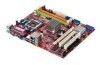
... hooks. 12. Press down to avoid damaging. Installing Memory Modules 1. You can barely see the golden finger if the memory module is properly inserted in BIOS. Notch Vo l t 5 Whenever CPU is deeply inserted in the right orientation. 2. The plastic clip at the sides. The appearance of the CPU/cooler installation only...
... hooks. 12. Press down to avoid damaging. Installing Memory Modules 1. You can barely see the golden finger if the memory module is properly inserted in BIOS. Notch Vo l t 5 Whenever CPU is deeply inserted in the right orientation. 2. The plastic clip at the sides. The appearance of the CPU/cooler installation only...
User Guide
Page 13
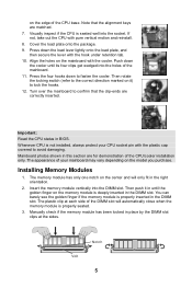
... record this status and show a warning message on -board, you must use a specially designed fan with +12V. To clear the warning, you must enter the BIOS utility and clear the record. L GND R JFP2 87 Speaker Power LED 21 JFP1 12 + -- + -+ HDD LED Power LED Reset Switch Power Switch 9 10 USB1+ USB1...
... record this status and show a warning message on -board, you must use a specially designed fan with +12V. To clear the warning, you must enter the BIOS utility and clear the record. L GND R JFP2 87 Speaker Power LED 21 JFP1 12 + -- + -+ HDD LED Power LED Reset Switch Power Switch 9 10 USB1+ USB1...
User Guide
Page 15
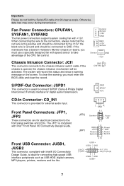
... Routing The IRQ, acronym of interrupt request line and pronounced I-R-Q, are typically connected to the PCI bus pins as jumpers, switches or BIOS configuration. Main Page 9 Meanwhile, read the documentation for the expansion card to configure any necessary hardware or software settings for the expansion card..., such as follows: PCI Slot1 PCI Slot2 Order1 INT A# INT B# Order2 INT B# INT C# Order3 INT C# INT D# Order4 INT D# INT A# BIOS Setup Power on the computer and the system will start POST (Power On Self Test) process. When the message below appears on the screen, press...
... Routing The IRQ, acronym of interrupt request line and pronounced I-R-Q, are typically connected to the PCI bus pins as jumpers, switches or BIOS configuration. Main Page 9 Meanwhile, read the documentation for the expansion card to configure any necessary hardware or software settings for the expansion card..., such as follows: PCI Slot1 PCI Slot2 Order1 INT A# INT B# Order2 INT B# INT C# Order3 INT C# INT D# Order4 INT D# INT A# BIOS Setup Power on the computer and the system will start POST (Power On Self Test) process. When the message below appears on the screen, press...
User Guide
Page 16
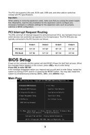
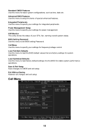
... values that are factory settings for power management. Load Fail-Safe Defaults Use this menu to set BIOS setting Password. Power Management Setup Use this menu to specify your settings for system operations. Exit Without Saving Abandon all changes and ... warning overall system status. Integrated Peripherals Use this menu to load factory default settings into the BIOS for frequency/voltage control. Cell Menu 10 Standard CMOS Features Use this menu for integrated peripherals. Advanced BIOS Features Use this menu to CMOS and exit setup. Save & Exit Setup Save changes to...
... values that are factory settings for power management. Load Fail-Safe Defaults Use this menu to set BIOS setting Password. Power Management Setup Use this menu to specify your settings for system operations. Exit Without Saving Abandon all changes and ... warning overall system status. Integrated Peripherals Use this menu to load factory default settings into the BIOS for frequency/voltage control. Cell Menu 10 Standard CMOS Features Use this menu for integrated peripherals. Advanced BIOS Features Use this menu to CMOS and exit setup. Save & Exit Setup Save changes to...
User Guide
Page 17
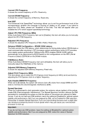
...this item will appear after receiving it. [2T] increases system performance while [2.5T] provides more stable system performance. Spread Spectrum When the motherboard's clock generator pulses, the extreme values (spikes) of CPU. Remember to disable Spread Spectrum if you to set "Disabled" in clock speed...EMI problem, leave the setting at [Disabled] for optimal system stability and performance. The Spread Spectrum function reduces the EMI generated by BIOS based on the configurations on the SPD (Serial Presence Detect) EEPROM on battery or AC power. Setting to [By SPD] enables...
...this item will appear after receiving it. [2T] increases system performance while [2.5T] provides more stable system performance. Spread Spectrum When the motherboard's clock generator pulses, the extreme values (spikes) of CPU. Remember to disable Spread Spectrum if you to set "Disabled" in clock speed...EMI problem, leave the setting at [Disabled] for optimal system stability and performance. The Spread Spectrum function reduces the EMI generated by BIOS based on the configurations on the SPD (Serial Presence Detect) EEPROM on battery or AC power. Setting to [By SPD] enables...
User Guide
Page 65
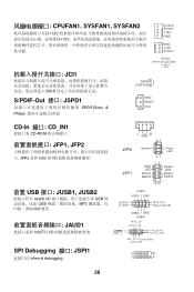
GND (2)VCC (1 )VC C N.C.(10) Key,no pin(9) (2)GND (1)MIC_L USB0- CPUFAN1, SYSFAN1, SYSFAN2 12V 12V Control Sensor +12V GND GND +12V Sensor JCI1 BIOS S/PDIF-Out 接口: JSPD1 SPDIF(Sony & Philips Sensor GND +12V GND 2 CINTRU 1 GND SPDIF VCC CD-In 接口: CD_IN1 CD-ROM JFP1, JFP2 ...
GND (2)VCC (1 )VC C N.C.(10) Key,no pin(9) (2)GND (1)MIC_L USB0- CPUFAN1, SYSFAN1, SYSFAN2 12V 12V Control Sensor +12V GND GND +12V Sensor JCI1 BIOS S/PDIF-Out 接口: JSPD1 SPDIF(Sony & Philips Sensor GND +12V GND 2 CINTRU 1 GND SPDIF VCC CD-In 接口: CD_IN1 CD-ROM JFP1, JFP2 ...
User Guide
Page 66
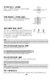
... 1 2 3 Keep Data 1 2 3 Clear Data 2-3 CMOS 1-2 CMOS PCI Express 插槽 PCI Express PCI Express PCI Express x 16 4.0 GB/s PCI 此 PCI SCSI 卡,USB PCI BIOS 配置. PCI IRQ 60
... 1 2 3 Keep Data 1 2 3 Clear Data 2-3 CMOS 1-2 CMOS PCI Express 插槽 PCI Express PCI Express PCI Express x 16 4.0 GB/s PCI 此 PCI SCSI 卡,USB PCI BIOS 配置. PCI IRQ 60
User Guide
Page 68
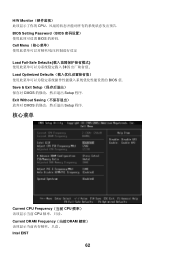
Save & Exit Setup CMOS Setup 程序. Cell Menu Load Fail-Safe Defaults BIOS Load Optimized Defaults BIOS 值. Exit Without Saving CMOS Setup 程序. 核心菜单 Current CPU Frequency(当前 CPU CPU Current DRAM Frequency(当前 DRAM Intel EIST 62 H/W Monitor CPU BIOS Setting Password(BIOS BIOS 的密码.
Save & Exit Setup CMOS Setup 程序. Cell Menu Load Fail-Safe Defaults BIOS Load Optimized Defaults BIOS 值. Exit Without Saving CMOS Setup 程序. 核心菜单 Current CPU Frequency(当前 CPU CPU Current DRAM Frequency(当前 DRAM Intel EIST 62 H/W Monitor CPU BIOS Setting Password(BIOS BIOS 的密码.
User Guide
Page 77
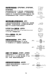
... Speaker Power LED 21 JFP1 12 + -- + -+ HDD LED Power LED Reset Switch Power Switch 9 10 USB1+ USB1- CPUFAN1, SYSFAN1, SYSFAN2 12V 12V GND CPU JCI1 BIOS Control Sensor +12V GND GND +12V Sensor Sensor GND +12V GND 2 CINTRU 1 S/PDIF-Out 連接器: JSPD1 S/PDIF (Sony & Philip Digital Interconnect Format GND...
... Speaker Power LED 21 JFP1 12 + -- + -+ HDD LED Power LED Reset Switch Power Switch 9 10 USB1+ USB1- CPUFAN1, SYSFAN1, SYSFAN2 12V 12V GND CPU JCI1 BIOS Control Sensor +12V GND GND +12V Sensor Sensor GND +12V GND 2 CINTRU 1 S/PDIF-Out 連接器: JSPD1 S/PDIF (Sony & Philip Digital Interconnect Format GND...
User Guide
Page 80
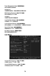
Power Management Setup H/W Monitor BIOS Setting Password(設定 BIOS BIOS 密碼。 Cell Menu Load Fail-Safe Defaults BIOS Load Optimized Defaults BIOS Save & Exit Setup CMOS Exit Without Saving Cell Menu Current CPU Frequency(目前 CPU CPU Current DRAM Frequency(目前 CPU DRAM 74
Power Management Setup H/W Monitor BIOS Setting Password(設定 BIOS BIOS 密碼。 Cell Menu Load Fail-Safe Defaults BIOS Load Optimized Defaults BIOS Save & Exit Setup CMOS Exit Without Saving Cell Menu Current CPU Frequency(目前 CPU CPU Current DRAM Frequency(目前 CPU DRAM 74
User Guide
Page 89
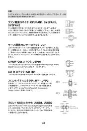
注意: ATA 90 CPUFAN1, SYSFAN1, SYSFAN2 12V 12V GND JCI1 BIOS Control Sensor +12V GND GND +12V Sensor Sensor GND +12V GND 2 CINTRU 1 S/PDIF-Out JSPD1 SPDIF(Sony& Philips Digital Interconnect Format GND SPDIF VCC CD-...
注意: ATA 90 CPUFAN1, SYSFAN1, SYSFAN2 12V 12V GND JCI1 BIOS Control Sensor +12V GND GND +12V Sensor Sensor GND +12V GND 2 CINTRU 1 S/PDIF-Out JSPD1 SPDIF(Sony& Philips Digital Interconnect Format GND SPDIF VCC CD-...
User Guide
Page 92
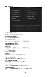
Standard CMOS Features Advanced BIOS Features Integrated Peripherals IDE I/O Power Management Setup H/W Monitor CPU BIOS Setting Password Cell Menu Load Fail-Safe Defaults BIOS Load Optimized Defaults BIOS Save & Exit Setup CMOS Exit Without Saving CMOS 86
Standard CMOS Features Advanced BIOS Features Integrated Peripherals IDE I/O Power Management Setup H/W Monitor CPU BIOS Setting Password Cell Menu Load Fail-Safe Defaults BIOS Load Optimized Defaults BIOS Save & Exit Setup CMOS Exit Without Saving CMOS 86


