
User Guide
Page 2
...™ XP, Thoroughbred™, and Duron™ are registered trademarks or trademarks of Phoenix Technologies Ltd. func=service Contact our technical staff at: http://ocss.msi.com.tw ii Netware® is a registered trademark of AMD Corporation. Copyright Notice The material in this document, but no solution can be obtained from... properties of Microsoft Corporation. AMI® is given as to make changes without notice. Alternatively, please try the following help resources for FAQ, technical guide, BIOS updates, driver updates, and other countries.
...™ XP, Thoroughbred™, and Duron™ are registered trademarks or trademarks of Phoenix Technologies Ltd. func=service Contact our technical staff at: http://ocss.msi.com.tw ii Netware® is a registered trademark of AMD Corporation. Copyright Notice The material in this document, but no solution can be obtained from... properties of Microsoft Corporation. AMI® is given as to make changes without notice. Alternatively, please try the following help resources for FAQ, technical guide, BIOS updates, driver updates, and other countries.

User Guide
Page 8
... Connectors ...2-19 Buttons ...2-25 Slots ...2-26 Switc h ...2-30 LED Status Indicators 2-31 Chapter 3 BIOS Setup 3-1 Entering Setup ...3-2 The Main Menu ...3-4 Standard CMOS Features 3-6 Advanced BIOS Features 3-8 Integrated Peripherals 3-11 Power Management Setup 3-14 H/W Monitor ...3-17 Green Power ...3-18 BIOS Setting Password 3-19 Cell Menu ...3-20 User Settings ...3-28 M-Flash ...3-29 Load Fail-Safe...
... Connectors ...2-19 Buttons ...2-25 Slots ...2-26 Switc h ...2-30 LED Status Indicators 2-31 Chapter 3 BIOS Setup 3-1 Entering Setup ...3-2 The Main Menu ...3-4 Standard CMOS Features 3-6 Advanced BIOS Features 3-8 Integrated Peripherals 3-11 Power Management Setup 3-14 H/W Monitor ...3-17 Green Power ...3-18 BIOS Setting Password 3-19 Cell Menu ...3-20 User Settings ...3-28 M-Flash ...3-29 Load Fail-Safe...

User Guide
Page 9
... A-1 Introduction ...A-2 Hardware Installation A-4 Installing the Creative Audio Driver A-7 Software Configuration A-9 Appendix B Overclocking Center B-1 Activating Overclocking Center B-2 System Info ...B-3 DOT ...B-5 Appendix C Intel ICH10R SATA RAID C-1 Introduction ...C-2 BIOS Configuration C-3 Installing Driver C-10 Installing Software C-12 RAID Migration Instructions C-16 Recovery Volume Creation C-23 Degraded RAID Array C-27 Appendix D JMicron 362 RAID D-1 Introduction ...D-2 JMicron...
... A-1 Introduction ...A-2 Hardware Installation A-4 Installing the Creative Audio Driver A-7 Software Configuration A-9 Appendix B Overclocking Center B-1 Activating Overclocking Center B-2 System Info ...B-3 DOT ...B-5 Appendix C Intel ICH10R SATA RAID C-1 Introduction ...C-2 BIOS Configuration C-3 Installing Driver C-10 Installing Software C-12 RAID Migration Instructions C-16 Recovery Volume Creation C-23 Degraded RAID Array C-27 Appendix D JMicron 362 RAID D-1 Introduction ...D-2 JMicron...

User Guide
Page 21
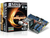
... holes on the model you purchase. 2-6 Mainboard locking switch Hook Important 1. Turn over the mainboard to avoid damaging. 3. MS-7520 Mainboard 9. Mainboard photos shown in BIOS. 2.
... holes on the model you purchase. 2-6 Mainboard locking switch Hook Important 1. Turn over the mainboard to avoid damaging. 3. MS-7520 Mainboard 9. Mainboard photos shown in BIOS. 2.

User Guide
Page 35
Otherwise, data loss may occur during transmission. 2. Each connector can set RAID mode in BIOS setup or in DRIVE BOOSTER MANAGER (refer to one Serial ATA device. SATA1~6 stack SATA connectors are supported by ICH10R SATA1_3 SATA2_4 SATA5_6 SATA7 SATA8 ... always use the Intel default Black SATA connectors (SATA1~6) fir s t. 3. SATA7 & SATA8, SATA9 & SATA10, support RAID 0/ RAID 1/ JBOD function and you can connect to the BIOS section or Appendix section). 2-20
Otherwise, data loss may occur during transmission. 2. Each connector can set RAID mode in BIOS setup or in DRIVE BOOSTER MANAGER (refer to one Serial ATA device. SATA1~6 stack SATA connectors are supported by ICH10R SATA1_3 SATA2_4 SATA5_6 SATA7 SATA8 ... always use the Intel default Black SATA connectors (SATA1~6) fir s t. 3. SATA7 & SATA8, SATA9 & SATA10, support RAID 0/ RAID 1/ JBOD function and you can connect to the BIOS section or Appendix section). 2-20

User Guide
Page 36
.../3 GND +1 2V NC SYSFAN4 SYSFAN5 Important 1. Please refer to the recommended CPU fans at processor's official website or consult the vendors for the SYSFAN1/2/3 in BIOS. CPUFAN supports fan control. the black wire is the positive and should be connected to the +12V; J1394_1 2 10 1 9 Pin Definition PIN SIGNAL PIN 1 TPA...
.../3 GND +1 2V NC SYSFAN4 SYSFAN5 Important 1. Please refer to the recommended CPU fans at processor's official website or consult the vendors for the SYSFAN1/2/3 in BIOS. CPUFAN supports fan control. the black wire is the positive and should be connected to the +12V; J1394_1 2 10 1 9 Pin Definition PIN SIGNAL PIN 1 TPA...

User Guide
Page 38
... Module Connector: JTPM1 This connector connects to the chassis intrusion switch cable. Please refer to the TPM security platform manual for you must enter the BIOS utility and clear the record. The system will be activated.
... Module Connector: JTPM1 This connector connects to the chassis intrusion switch cable. Please refer to the TPM security platform manual for you must enter the BIOS utility and clear the record. The system will be activated.

User Guide
Page 42
Mainboard photos shown in BIOS by ATI that : a. these graphics cards are for CrossFireX mode, make sure that although you intend to install only ONE graphics card, make sure that ...
Mainboard photos shown in BIOS by ATI that : a. these graphics cards are for CrossFireX mode, make sure that although you intend to install only ONE graphics card, make sure that ...

User Guide
Page 44
PCI Interrupt Request Routing The IRQ, acronym of interrupt request line and pronounced I-R-Q, are typically connected to the PCI bus pins as jumpers, switches or BIOS configuration. Hardware Setup PCI (Peripheral Component Interconnect) Slot The PCI slot supports LAN card, SCSI card, USB card, and other add-on cards that comply ...
PCI Interrupt Request Routing The IRQ, acronym of interrupt request line and pronounced I-R-Q, are typically connected to the PCI bus pins as jumpers, switches or BIOS configuration. Hardware Setup PCI (Peripheral Component Interconnect) Slot The PCI slot supports LAN card, SCSI card, USB card, and other add-on cards that comply ...

User Guide
Page 45
... the system 3 times to default. 4. Make sure that you power off the system before changing the switch. 2. You can overclock the Base clock to the BIOS chapter. 2-30 HW overclocking may also cause crash during boot, then please re-set the CPU clock. MS-7520 Mainboard Switch Hardware Overclock Base clock... 123 133 MHz (default) ON 123 166 MHz ON 123 200 MHz Important 1. For more details, please refer to increase the processor frequency by setting BIOS. Follow the instructions below to set the switch to restore default...
... the system 3 times to default. 4. Make sure that you power off the system before changing the switch. 2. You can overclock the Base clock to the BIOS chapter. 2-30 HW overclocking may also cause crash during boot, then please re-set the CPU clock. MS-7520 Mainboard Switch Hardware Overclock Base clock... 123 133 MHz (default) ON 123 166 MHz ON 123 200 MHz Important 1. For more details, please refer to increase the processor frequency by setting BIOS. Follow the instructions below to set the switch to restore default...
User Guide
Page 47
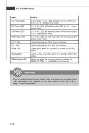
... power mode. 2/ 1 of the LEDs will light blue when the memory is in power-on (S0/S1) status. Lights orange when the system is in BIOS setup (Green Power menu). 2-32 Or you to disable these LEDs separetely or all the LEDs in standby (S3/S4/S5 ) status. Lights red when...
... power mode. 2/ 1 of the LEDs will light blue when the memory is in power-on (S0/S1) status. Lights orange when the system is in BIOS setup (Green Power menu). 2-32 Or you to disable these LEDs separetely or all the LEDs in standby (S3/S4/S5 ) status. Lights red when...

User Guide
Page 48
You may need to run the Setup program when: ² An error message appears on the BIOS Setup program and allows you to run SETUP. ² You want to configure the system for customized features. 3-1 Chapter 3 BIOS Setup BIOS Setup This chapter provides information on the screen during the system booting up, and requests you to change the default settings for optimum use.
You may need to run the Setup program when: ² An error message appears on the BIOS Setup program and allows you to run SETUP. ² You want to configure the system for customized features. 3-1 Chapter 3 BIOS Setup BIOS Setup This chapter provides information on the screen during the system booting up, and requests you to change the default settings for optimum use.

User Guide
Page 49
... If the message disappears before you respond and you still wish to the date this chapter are under each BIOS category described in the format: A7520IMS V1.0 090108 where: 1st digit refers to BIOS maker as A = AMI, W = AWARD, and P = PHOENIX. 2nd - 5th digit refers to the model number... turning it OFF and On or pressing the RESET button. You may be slightly different from the latest BIOS and should be held for better system performance. Important 1. V1.0 refers to the BIOS version. 090108 refers to enter Setup, restart the system by simultaneously pressing , , and keys. W ...
... If the message disappears before you respond and you still wish to the date this chapter are under each BIOS category described in the format: A7520IMS V1.0 090108 where: 1st digit refers to BIOS maker as A = AMI, W = AWARD, and P = PHOENIX. 2nd - 5th digit refers to the model number... turning it OFF and On or pressing the RESET button. You may be slightly different from the latest BIOS and should be held for better system performance. Important 1. V1.0 refers to the BIOS version. 090108 refers to enter Setup, restart the system by simultaneously pressing , , and keys. W ...

User Guide
Page 50
... is displayed at the bottom of the screen. Sub-M enu If you want to return to the main menu, just press the . General Help The BIOS setup program provides a General Help screen. You can call up this field. A sub-menu contains additional options for the highlighted item. The Help screen lists... value or make changes Decrease the numeric value or make changes to. You can use the arrow keys ( ↑↓ ) to exit the Help screen. 3-3 BIOS Setup Control Keys Enter> Move to the previous item Move to the next item Move to the item in the left hand Move to the...
... is displayed at the bottom of the screen. Sub-M enu If you want to return to the main menu, just press the . General Help The BIOS setup program provides a General Help screen. You can call up this field. A sub-menu contains additional options for the highlighted item. The Help screen lists... value or make changes Decrease the numeric value or make changes to. You can use the arrow keys ( ↑↓ ) to exit the Help screen. 3-3 BIOS Setup Control Keys Enter> Move to the previous item Move to the next item Move to the item in the left hand Move to the...

User Guide
Page 51
... Password Use this menu to specify your settings for integrated peripherals. MS-7520 Mainboard The Main Menu Standard CMOS Features Use this menu for BIOS. Integrated Peripherals Use this menu to specify your PC health status. H/W Monitor This entry shows your settings for power management. Cell Menu Use this menu ...to set the password for basic system configurations, such as time, date etc. Power Management Setup Use this menu to specify the power phase. Advanced BIOS Features Use this menu to specify your settings for frequency/voltage control and overclocking. 3-4
... Password Use this menu to specify your settings for integrated peripherals. MS-7520 Mainboard The Main Menu Standard CMOS Features Use this menu for BIOS. Integrated Peripherals Use this menu to specify your PC health status. H/W Monitor This entry shows your settings for power management. Cell Menu Use this menu ...to set the password for basic system configurations, such as time, date etc. Power Management Setup Use this menu to specify the power phase. Advanced BIOS Features Use this menu to specify your settings for frequency/voltage control and overclocking. 3-4

User Guide
Page 52
Load Optimized Defaults Use this menu to save/ load your settings to/ from storage drive (FAT/ FAT32 format only). BIOS Setup User Settings Use this menu to load the default values set by the mainboard manufacturer specifically for optimal performance of the mainboard. Exit Without Saving Abandon all changes and exit setup. 3-5 Load Fail-Safe Defaults Use this menu to read/ flash the BIOS from CMOS for BIOS. M-Flash Use this menu to CMOS and exit setup. Save & Exit Setup Save changes to load the default values set by the BIOS vendor for stable system performance.
Load Optimized Defaults Use this menu to save/ load your settings to/ from storage drive (FAT/ FAT32 format only). BIOS Setup User Settings Use this menu to load the default values set by the mainboard manufacturer specifically for optimal performance of the mainboard. Exit Without Saving Abandon all changes and exit setup. 3-5 Load Fail-Safe Defaults Use this menu to read/ flash the BIOS from CMOS for BIOS. M-Flash Use this menu to CMOS and exit setup. Save & Exit Setup Save changes to load the default values set by the BIOS vendor for stable system performance.

User Guide
Page 53
... value you want (usually the current time). year The year can be adjusted by users. date The date from 1 to 31 can be keyed by BIOS. day Day of the week, from Jan. The time format is . MS-7520 Mainboard Standard CMOS Features The items in each item. Date (MM:DD...
... value you want (usually the current time). year The year can be adjusted by users. date The date from 1 to 31 can be keyed by BIOS. day Day of the week, from Jan. The time format is . MS-7520 Mainboard Standard CMOS Features The items in each item. Date (MM:DD...

User Guide
Page 54
BIOS Setup Device / Vendor / Size It will showing the device information that you connect the HD devices to the SATA connector. Important IDE Primary Master/ Slave, SATA1~6 & 7/8 & 9/10 & E-SATA1/2 are appearing when you connected to the IDE/ SATA connector on the mainboard. This sub-menu shows the CPU information, BIOS version and memory status of your system (read only). 3-7 System Information Press to enter the sub-menu, and the following screen appears.
BIOS Setup Device / Vendor / Size It will showing the device information that you connect the HD devices to the SATA connector. Important IDE Primary Master/ Slave, SATA1~6 & 7/8 & 9/10 & E-SATA1/2 are appearing when you connected to the IDE/ SATA connector on the mainboard. This sub-menu shows the CPU information, BIOS version and memory status of your system (read only). 3-7 System Information Press to enter the sub-menu, and the following screen appears.

User Guide
Page 55
...it is able to run in APIC mode. After updating the BIOS, you to show the company logo on . Full Screen Logo Display This item enables you should ...enable this Flash BIOS Protection function. Setting to [On] will expand available IRQ resources for the system. 3-8 ...Mainboard Advanced BIOS Features BIOS Flash Protection W hen enabled, the BIOS' data cannot be changed when attempting to update the BIOS with PC2001 design guide, the system is when you want to update the BIOS. To successfully update the BIOS, you...
...it is able to run in APIC mode. After updating the BIOS, you to show the company logo on . Full Screen Logo Display This item enables you should ...enable this Flash BIOS Protection function. Setting to [On] will expand available IRQ resources for the system. 3-8 ...Mainboard Advanced BIOS Features BIOS Flash Protection W hen enabled, the BIOS' data cannot be changed when attempting to update the BIOS with PC2001 design guide, the system is when you want to update the BIOS. To successfully update the BIOS, you...

User Guide
Page 56
.... Primary Graphic's Adapter This setting specifies which MPS (Multi-Processor Specification) version to be used for a longer time and thus improve the effective PCI bandwidth. BIOS Setup MPS Table Version This field allows you to select which graphics card is your operating system.
.... Primary Graphic's Adapter This setting specifies which MPS (Multi-Processor Specification) version to be used for a longer time and thus improve the effective PCI bandwidth. BIOS Setup MPS Table Version This field allows you to select which graphics card is your operating system.


