
User Guide
Page 4
... provide reasonable protection against harmful interference in a particular installation. However, there is no guarantee that interference will not occur in a residential installation. Micro-Star International MS-7520 This device complies with the emission limits. Notice 1 The changes or modifications not expressly approved by one or more of the measures listed below...
... provide reasonable protection against harmful interference in a particular installation. However, there is no guarantee that interference will not occur in a residential installation. Micro-Star International MS-7520 This device complies with the emission limits. Notice 1 The changes or modifications not expressly approved by one or more of the measures listed below...

User Guide
Page 10
Designed to fit the advanced Intel® i7 LGA1366 processor, the Eclipse delivers a high performance and professional desktop platform solution. 1-1 The Eclipse mainboard is based on Intel® X58 & ICH10R chipsets for choosing the Eclipse (MS-7520 v1.X) ATX mainboard. Getting Started Chapter 1 Getting Started Thank you for optimal system ef ficiency.
Designed to fit the advanced Intel® i7 LGA1366 processor, the Eclipse delivers a high performance and professional desktop platform solution. 1-1 The Eclipse mainboard is based on Intel® X58 & ICH10R chipsets for choosing the Eclipse (MS-7520 v1.X) ATX mainboard. Getting Started Chapter 1 Getting Started Thank you for optimal system ef ficiency.

User Guide
Page 11
.../ 4Gb DRAM size - Supports up to 3 channels mode (For more information on back panel support RAID 0/ 1 & JBOD mode by JMicron JMB362 - Up to 6.4 GT/s Chipset - MS-7520 Mainboard Mainboard Specifications Processor Support - ICH: Intel® ICH10R chipset Memory Support - 6 DDR3 DIMMs support DDR3 1333/ 1066/ 800 DRAM speed (Memory size 24GB...
.../ 4Gb DRAM size - Supports up to 3 channels mode (For more information on back panel support RAID 0/ 1 & JBOD mode by JMicron JMB362 - Up to 6.4 GT/s Chipset - MS-7520 Mainboard Mainboard Specifications Processor Support - ICH: Intel® ICH10R chipset Memory Support - 6 DDR3 DIMMs support DDR3 1333/ 1066/ 800 DRAM speed (Memory size 24GB...

User Guide
Page 13
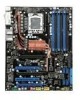
JPWR1 MS-7520 Mainboard Mainboard Layout JPWR2 Top : mouse Botto m: keyboard Top: USB por ts Botto m: 1394 port eSATA por ts CP U FA N C L R_ C OM S 1 Top: LAN ... ICH10R J SM B1 S Y SFA N 3 BATT + JCI1 SATA5_6 SATA2_4 JMB322 SATA7 SATA8 SYSFAN2 I/O Chip JMB363 JUS B1 JMB322 JDLED2 SATA9 SATA10 IDE1 JCOM1 JTPM 1JFP2 JFP1 Eclipse (MS-7520 v1.X) ATX Mainboard SATA1 _3 1-4
JPWR1 MS-7520 Mainboard Mainboard Layout JPWR2 Top : mouse Botto m: keyboard Top: USB por ts Botto m: 1394 port eSATA por ts CP U FA N C L R_ C OM S 1 Top: LAN ... ICH10R J SM B1 S Y SFA N 3 BATT + JCI1 SATA5_6 SATA2_4 JMB322 SATA7 SATA8 SYSFAN2 I/O Chip JMB363 JUS B1 JMB322 JDLED2 SATA9 SATA10 IDE1 JCOM1 JTPM 1JFP2 JFP1 Eclipse (MS-7520 v1.X) ATX Mainboard SATA1 _3 1-4

User Guide
Page 19
... protect the socket pin. Follow the steps below to protect the contack from the lever hinge side (as the arrow shows). 4. Before you are matched. MS-7520 Mainboard CPU & Cooler Installation W hen you install CPU, always cover it to install the CPU & cooler correctly. alignment key 2-4 The CPU socket has a plastic...
... protect the socket pin. Follow the steps below to protect the contack from the lever hinge side (as the arrow shows). 4. Before you are matched. MS-7520 Mainboard CPU & Cooler Installation W hen you install CPU, always cover it to install the CPU & cooler correctly. alignment key 2-4 The CPU socket has a plastic...

User Guide
Page 21
... the model you purchase. 2-6 Push down the cooler until its four clips get wedged into the holes of your CPU socket pin with the heatsink. MS-7520 Mainboard 9. Whenever CPU is not installed, always protect your mainboard may vary depending on the mainboard with the plastic cap covered (shown in Figure...
... the model you purchase. 2-6 Push down the cooler until its four clips get wedged into the holes of your CPU socket pin with the heatsink. MS-7520 Mainboard 9. Whenever CPU is not installed, always protect your mainboard may vary depending on the mainboard with the plastic cap covered (shown in Figure...

User Guide
Page 23
Enabling Three-Channel mode can transmit and receive data with three data bus lines simultaneously. MS-7520 Mainboard Three-Channel mode In Three-Channel mode, the memory modules can enhance the best system performance. W hen you have three or more memory ...
Enabling Three-Channel mode can transmit and receive data with three data bus lines simultaneously. MS-7520 Mainboard Three-Channel mode In Three-Channel mode, the memory modules can enhance the best system performance. W hen you have three or more memory ...

User Guide
Page 25
MS-7520 Mainboard Installing Memory Modules 1. Manually check if the memory module has been locked in place by the DIMM slot clips at each side of ...
MS-7520 Mainboard Installing Memory Modules 1. Manually check if the memory module has been locked in place by the DIMM slot clips at each side of ...

User Guide
Page 29
... KVR1333D3N9/1G (Elpida J1108BASE-DJ-E) 2-14 Size 512MB 512MB 1GB 1GB 1GB Memory slot A1 A0 B1 B0 C1 C0 V V V V V VV V V V V V V V VV V V V V V V V V V VV V V V V V V V VV V V VVVVVV MS-7520 Mainboard Vendor TAKEMS Model TMS1GB364D081-107EQ (With iron case) Bufaullo D3/1066-2G (Micron D9GTR) Crucial CT25664BA1067.16SFD (Micron D9JNL) HYNIX HMT125U6AFP8C-G7N0 (Hynix...
... KVR1333D3N9/1G (Elpida J1108BASE-DJ-E) 2-14 Size 512MB 512MB 1GB 1GB 1GB Memory slot A1 A0 B1 B0 C1 C0 V V V V V VV V V V V V V V VV V V V V V V V V V VV V V V V V V V VV V V VVVVVV MS-7520 Mainboard Vendor TAKEMS Model TMS1GB364D081-107EQ (With iron case) Bufaullo D3/1066-2G (Micron D9GTR) Crucial CT25664BA1067.16SFD (Micron D9JNL) HYNIX HMT125U6AFP8C-G7N0 (Hynix...

User Guide
Page 31
...-pin power supply. Power supply of the power supply is inserted in the proper orientation and the pins are connected to proper ATX power supplies to the CPU. 4 8 JPWR2 1 5 Pin Definition PIN SIGNAL PIN SIGNAL 1 GND 2 GND 3 GND 4 GND 5 +12V 6 +12V 7 +12V 8 +12V Important 1. ... watts (and above) is highly recommended for system stability. 3. ATX 12V power connection should be greater than 18A. 2-16 MS-7520 Mainboard Power Supply ATX 24-Pin Power Connector: JPWR1 This connector allows you like to use the 20-pin ATX power supply, please plug your power supply along with pin 1...
...-pin power supply. Power supply of the power supply is inserted in the proper orientation and the pins are connected to proper ATX power supplies to the CPU. 4 8 JPWR2 1 5 Pin Definition PIN SIGNAL PIN SIGNAL 1 GND 2 GND 3 GND 4 GND 5 +12V 6 +12V 7 +12V 8 +12V Important 1. ... watts (and above) is highly recommended for system stability. 3. ATX 12V power connection should be greater than 18A. 2-16 MS-7520 Mainboard Power Supply ATX 24-Pin Power Connector: JPWR1 This connector allows you like to use the 20-pin ATX power supply, please plug your power supply along with pin 1...

User Guide
Page 33
On (steady state) LAN link is selected. 2-18 On 1000 Mbit/sec data rate is established. Off 10 Mbit/sec data rate is selected. On 100 Mbit/sec data rate is selected. On (brighter & pulsing) The computer is not established. Green / Orange LED Color Left Yellow Green Right Orange LED State Condition Off LAN link is communicating with another computer on the LAN. You can connect a network cable to the Local Area Network (LAN). MS-7520 Mainboard LAN The standard RJ-45 LAN jack is for connection Yellow to it.
On (steady state) LAN link is selected. 2-18 On 1000 Mbit/sec data rate is established. Off 10 Mbit/sec data rate is selected. On 100 Mbit/sec data rate is selected. On (brighter & pulsing) The computer is not established. Green / Orange LED Color Left Yellow Green Right Orange LED State Condition Off LAN link is communicating with another computer on the LAN. You can connect a network cable to the Local Area Network (LAN). MS-7520 Mainboard LAN The standard RJ-45 LAN jack is for connection Yellow to it.
User Guide
Page 35
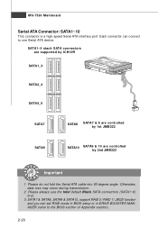
... into 90-degree angle. SATA7 & SATA8, SATA9 & SATA10, support RAID 0/ RAID 1/ JBOD function and you can connect to the BIOS section or Appendix section). 2-20 MS-7520 Mainboard Serial ATA Connector: SATA1~10 This connector is a high-speed Serial ATA interface port. Each connector can set RAID mode in BIOS setup...
... into 90-degree angle. SATA7 & SATA8, SATA9 & SATA10, support RAID 0/ RAID 1/ JBOD function and you can connect to the BIOS section or Appendix section). 2-20 MS-7520 Mainboard Serial ATA Connector: SATA1~10 This connector is a high-speed Serial ATA interface port. Each connector can set RAID mode in BIOS setup...

User Guide
Page 37
... LED BuzzerNo connection Speaker+ Serial Port Connector: JCOM1 This connector is compliant with Intel® Front Panel I/O Connectivity Design Guide. You can attach a serial device. MS-7520 Mainboard Front Panel Connectors: JFP1, JFP2 These connectors are for electrical connection to GND Reserved. The JFP1 is a 16550A high speed communication port that...
... LED BuzzerNo connection Speaker+ Serial Port Connector: JCOM1 This connector is compliant with Intel® Front Panel I/O Connectivity Design Guide. You can attach a serial device. MS-7520 Mainboard Front Panel Connectors: JFP1, JFP2 These connectors are for electrical connection to GND Reserved. The JFP1 is a 16550A high speed communication port that...

User Guide
Page 39
MS-7520 Mainboard Front USB Connector: JUSB1/ JUSB2 These connectors, compliant with Intel® I/O Connectivity Design Guide, is ideal for more details and usages. 2 1 JSM B1 2-...
MS-7520 Mainboard Front USB Connector: JUSB1/ JUSB2 These connectors, compliant with Intel® I/O Connectivity Design Guide, is ideal for more details and usages. 2 1 JSM B1 2-...

User Guide
Page 41
... Black PCIEx16 slots and 3-way CrossFireXTM with all the three PCIE x16 slots. 2-26 The PCI Express x1 supports up to 250 MB/s transfer rate. MS-7520 Mainboard Slots PCI (Peripheral Component Interconnect) Express Slot The PCI Express slot supports the PCI Express interface expansion card. The PCI Express 2.0 x4 supports...
... Black PCIEx16 slots and 3-way CrossFireXTM with all the three PCIE x16 slots. 2-26 The PCI Express x1 supports up to 250 MB/s transfer rate. MS-7520 Mainboard Slots PCI (Peripheral Component Interconnect) Express Slot The PCI Express slot supports the PCI Express interface expansion card. The PCI Express 2.0 x4 supports...

User Guide
Page 43
MS-7520 Mainboard 3.W hen all of the hardware and software has been properly set up and installed, reboot the system. The following aspect appears in the ...
MS-7520 Mainboard 3.W hen all of the hardware and software has been properly set up and installed, reboot the system. The following aspect appears in the ...

User Guide
Page 45
MS-7520 Mainboard Switch Hardware Overclock Base clock Switch: CPU_CLK1 You can also overclock by changing this switch. Make sure that you power off the system ...
MS-7520 Mainboard Switch Hardware Overclock Base clock Switch: CPU_CLK1 You can also overclock by changing this switch. Make sure that you power off the system ...

User Guide
Page 47
... you may disable all together. Lights green when the system is in standby (S3/S4/S5 ) status. Lights blue when the PCI Slot is functional. MS-7520 Mainboard N am e CPU Phase LEDs QPI Phase LEDs IOH Phase LEDs DDR Phase LEDs PCI E LEDs PCI LEDs Power LED Standby LED DIMM Warning...
... you may disable all together. Lights green when the system is in standby (S3/S4/S5 ) status. Lights blue when the PCI Slot is functional. MS-7520 Mainboard N am e CPU Phase LEDs QPI Phase LEDs IOH Phase LEDs DDR Phase LEDs PCI E LEDs PCI LEDs Power LED Standby LED DIMM Warning...

User Guide
Page 49
...for better system performance. Important 1. Therefore, the description may also restart the system by turning it OFF and On or pressing the RESET button. MS-7520 Mainboard Entering Setup Power on the screen, press key to enter Setup. The items under continuous update for reference only. 2. V1.0 refers... model number. 6th digit refers to the chipset as I = Intel, N = nVidia, and V = VIA. 7th - 8th digit refers to the customer as MS = all standard customers. W hen the message below appears on the computer and the system will start POST (Power On Self Test) process. It is the...
...for better system performance. Important 1. Therefore, the description may also restart the system by turning it OFF and On or pressing the RESET button. MS-7520 Mainboard Entering Setup Power on the screen, press key to enter Setup. The items under continuous update for reference only. 2. V1.0 refers... model number. 6th digit refers to the chipset as I = Intel, N = nVidia, and V = VIA. 7th - 8th digit refers to the customer as MS = all standard customers. W hen the message below appears on the computer and the system will start POST (Power On Self Test) process. It is the...

User Guide
Page 51
Power Management Setup Use this menu for basic system configurations, such as time, date etc. MS-7520 Mainboard The Main Menu Standard CMOS Features Use this menu to specify your settings for power management. Integrated Peripherals Use this menu to set ...
Power Management Setup Use this menu for basic system configurations, such as time, date etc. MS-7520 Mainboard The Main Menu Standard CMOS Features Use this menu to specify your settings for power management. Integrated Peripherals Use this menu to set ...


