User Guide
Page 2
... given as to make changes without notice. Alternatively, please try the following help resources for FAQ, technical guide, BIOS updates, driver updates, and other countries. Visit the MSI website for further guidance. We take every care in the preparation of this document is the intellectual property of ... trademarks of NVIDIA Corporation in the United States and/or other information: http://www.msi.com.tw/program/service/faq/ faq/esc_faq_list.php Contact our technical staff at: http://support.msi.com.tw ii NVIDIA, the NVIDIA logo, DualNet, and nForce are registered trademarks ...
... given as to make changes without notice. Alternatively, please try the following help resources for FAQ, technical guide, BIOS updates, driver updates, and other countries. Visit the MSI website for further guidance. We take every care in the preparation of this document is the intellectual property of ... trademarks of NVIDIA Corporation in the United States and/or other information: http://www.msi.com.tw/program/service/faq/ faq/esc_faq_list.php Contact our technical staff at: http://support.msi.com.tw ii NVIDIA, the NVIDIA logo, DualNet, and nForce are registered trademarks ...
User Guide
Page 9
...Basic Function A-11 Non-Unicode programs supported A-13 Power On Agent A-14 ix BIOS Setup 3-1 Entering Setup ...3-2 Control Keys 3-3 Getting Help 3-3 The Main Menu ...3-4 Standard CMOS Features 3-6 Advanced BIOS Features 3-8 Advanced Chipset Features 3-10 Integrated Peripherals 3-12 Power Management Setup 3-...16 PNP/PCI Configurations 3-18 H/W Monitor ...3-20 Cell Menu ...3-22 Load Fail-safe/Optimized Deafaults 3-27 BIOS Setting Password 3-28 Appendix A. D-Bracket™ 2 Connector: JLED1 2-21 Clear CMOS Button: SW 2-23 Button ...2-23 ATi CrossFire...
...Basic Function A-11 Non-Unicode programs supported A-13 Power On Agent A-14 ix BIOS Setup 3-1 Entering Setup ...3-2 Control Keys 3-3 Getting Help 3-3 The Main Menu ...3-4 Standard CMOS Features 3-6 Advanced BIOS Features 3-8 Advanced Chipset Features 3-10 Integrated Peripherals 3-12 Power Management Setup 3-...16 PNP/PCI Configurations 3-18 H/W Monitor ...3-20 Cell Menu ...3-22 Load Fail-safe/Optimized Deafaults 3-27 BIOS Setting Password 3-28 Appendix A. D-Bracket™ 2 Connector: JLED1 2-21 Clear CMOS Button: SW 2-23 Button ...2-23 ATi CrossFire...
User Guide
Page 10
... B-21 Appendix C. JMicron RAID Introduction C-1 RAID - Intel ICH7HD SATA RAID B-1 Using the Intel Matrix Stroage Manager Option ROM B-2 BIOS Configuration B-2 Installing Software B-8 Install Driver in W indows XP / 2000 B-9 Installation of Independent Disks C-2 RAID 0 (Striping C-2 RAID... 1 (Mirroring C-2 JBOD (Concatenate C-2 Introduction ...C-2 Creating and Deleting RAID sets with BIOS Utility C-3 Main Menu ...C-3 Hard Disk Driver List C-3 RAID Disk Driver List C-3 Creating RAID set C-4 Deleting RAID set C-7 Revert HDD...
... B-21 Appendix C. JMicron RAID Introduction C-1 RAID - Intel ICH7HD SATA RAID B-1 Using the Intel Matrix Stroage Manager Option ROM B-2 BIOS Configuration B-2 Installing Software B-8 Install Driver in W indows XP / 2000 B-9 Installation of Independent Disks C-2 RAID 0 (Striping C-2 RAID... 1 (Mirroring C-2 JBOD (Concatenate C-2 Introduction ...C-2 Creating and Deleting RAID sets with BIOS Utility C-3 Main Menu ...C-3 Hard Disk Driver List C-3 RAID Disk Driver List C-3 Creating RAID set C-4 Deleting RAID set C-7 Revert HDD...
User Guide
Page 15
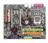
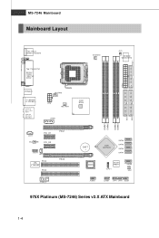
... JCD1 ALC882M PCI_E1 PCI_E2 PEG1 JAUD1 JSP1 PCI2 VIA VT6308P PCI3 PEG2 J1394_2 B ATT + BIOS Intel ICH7DH SATA4 SATA3 SATA2 SATA1 Jmi cro n JMB361 JLPC1 SATA5 SW1 JUSB2 JUSB1 JFP1 JFP2 JLED1 975X Platinum (MS-7246) Series v2.X ATX Mainboard 1-4 MS-7246 Mainboard Mainboard Layout FDD 1 DIMM1 DIMM2 DIMM3 DIMM4 I DE 1 I DE 2 Top : mouse...
... JCD1 ALC882M PCI_E1 PCI_E2 PEG1 JAUD1 JSP1 PCI2 VIA VT6308P PCI3 PEG2 J1394_2 B ATT + BIOS Intel ICH7DH SATA4 SATA3 SATA2 SATA1 Jmi cro n JMB361 JLPC1 SATA5 SW1 JUSB2 JUSB1 JFP1 JFP2 JLED1 975X Platinum (MS-7246) Series v2.X ATX Mainboard 1-4 MS-7246 Mainboard Mainboard Layout FDD 1 DIMM1 DIMM2 DIMM3 DIMM4 I DE 1 I DE 2 Top : mouse...

User Guide
Page 22
.... Press the four hooks down the load lever lightly onto the load plate, and then secure the lever with the plastic cap covered (shown in BIOS (Chapter 3) for details) again and push the clip to uninstall the CPU, align the 4 points (see Point 8 for the CPU temperature...
.... Press the four hooks down the load lever lightly onto the load plate, and then secure the lever with the plastic cap covered (shown in BIOS (Chapter 3) for details) again and push the clip to uninstall the CPU, align the 4 points (see Point 8 for the CPU temperature...

User Guide
Page 34
signals BIOS that the pins of 480Mbps, which is 40 times faster than USB 1.1, and is connected. 5 PORT 2R Analog Port 2 - Left channel 10 SENSE2_RETIRN Jack detection ...
signals BIOS that the pins of 480Mbps, which is 40 times faster than USB 1.1, and is connected. 5 PORT 2R Analog Port 2 - Left channel 10 SENSE2_RETIRN Jack detection ...
User Guide
Page 35
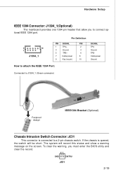
... connect optional IEEE 1394 port. Hardware Setup IEEE 1394 Connector: J1394_1(Optional) The mainboard provides one 1394 pin header that allow you must enter the BIOS utility and clear the record. 21 GND CINTRU JCI1 2-19 To clear the warning, you to J1394_1 (Green connector) Foolproof design IEEE1394 Bracket (Optional) Chassis...
... connect optional IEEE 1394 port. Hardware Setup IEEE 1394 Connector: J1394_1(Optional) The mainboard provides one 1394 pin header that allow you must enter the BIOS utility and clear the record. 21 GND CINTRU JCI1 2-19 To clear the warning, you to J1394_1 (Green connector) Foolproof design IEEE1394 Bracket (Optional) Chassis...
User Guide
Page 37
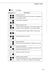
Decompressing BIOS image to the screen. Initializing Keyboard Controller. Then, detect and initialize the video adapter. 2-21 Early Chipset Initialization Memory Detection Test Testing onboard memory size. ... bus, etc...) Testing RTC (Real Time Clock) Initializing Video Interface This will start writing VGA sign-on message to RAM for fast booting. Testing VGA BIOS This will start detecting CPU clock, checking type of video onboard. Hardware Setup Red Green D-Bracket™ 2 Description System Power ON 1 2 The D-LED will hang...
Decompressing BIOS image to the screen. Initializing Keyboard Controller. Then, detect and initialize the video adapter. 2-21 Early Chipset Initialization Memory Detection Test Testing onboard memory size. ... bus, etc...) Testing RTC (Real Time Clock) Initializing Video Interface This will start writing VGA sign-on message to RAM for fast booting. Testing VGA BIOS This will start detecting CPU clock, checking type of video onboard. Hardware Setup Red Green D-Bracket™ 2 Description System Power ON 1 2 The D-LED will hang...
User Guide
Page 38
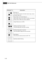
Boot Attempt This will initialize Floppy Drive and controller. Operating System Booting 2-22 Initializing Floppy Drive Controller This will set low stack and boot via INT 19h. Initializing Hard Drive Controller This will start showing information about logo, processor brand name, etc... Testing Base and Extended Memory Testing base memory from 240K to all ISA. Assign Resources to 640K and extended memory above 1MB using various patterns. MS-7246 Mainboard D-Bracket™ 2 Description BIOS Sign On This will initialize IDE drive and controller.
Boot Attempt This will initialize Floppy Drive and controller. Operating System Booting 2-22 Initializing Floppy Drive Controller This will set low stack and boot via INT 19h. Initializing Hard Drive Controller This will start showing information about logo, processor brand name, etc... Testing Base and Extended Memory Testing base memory from 240K to all ISA. Assign Resources to 640K and extended memory above 1MB using various patterns. MS-7246 Mainboard D-Bracket™ 2 Description BIOS Sign On This will initialize IDE drive and controller.
User Guide
Page 40
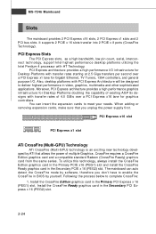
... utilize this technology, always install the CrossFire Edition graphics card in the Primary PCIE x16 (PEG1) slot and install the CrossFire Ready graphics card in BIOS by software, therefore you unplug the power supply first. PCI Express Slots The PCI Express slots, as a high-bandwidth, low pin count, serial, interconnect technology...
... utilize this technology, always install the CrossFire Edition graphics card in the Primary PCIE x16 (PEG1) slot and install the CrossFire Ready graphics card in BIOS by software, therefore you unplug the power supply first. PCI Express Slots The PCI Express slots, as a high-bandwidth, low pin count, serial, interconnect technology...
User Guide
Page 43
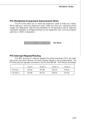
... for the expansion card to make sure that you to insert the expansion cards to the PCI bus INT A# ~ INT D# pins as jumpers, switches or BIOS configuration.
... for the expansion card to make sure that you to insert the expansion cards to the PCI bus INT A# ~ INT D# pins as jumpers, switches or BIOS configuration.

User Guide
Page 44
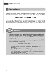
You may need to run the Setup program when: ² An error message appears on the BIOS Setup program and allows you to run SETUP. ² You want to configure the system for cus- tomized features. Chapter 3 BIOS Setup This chapter provides information on the screen during the system booting up, and requests you to change the default settings for optimum use.
You may need to run the Setup program when: ² An error message appears on the BIOS Setup program and allows you to run SETUP. ² You want to configure the system for cus- tomized features. Chapter 3 BIOS Setup This chapter provides information on the screen during the system booting up, and requests you to change the default settings for optimum use.
User Guide
Page 45
... still wish to enter Setup, restart the system by simultaneously pressing , , and keys. Important 1. The items under each BIOS category described in the format: W9628IMS V1.0 031505 where: 1st digit refers to BIOS maker as A = AMI, W = AWARD, and P = PHOENIX. 2nd - 5th digit refers to the model number... hen the message below appears on the computer and the system will start POST (Power On Self Test) process. V1.0 refers to the BIOS version. 031505 refers to the date this chapter are under continuous update for reference only. 2. MS-7246 Mainboard Entering Setup Power on the screen...
... still wish to enter Setup, restart the system by simultaneously pressing , , and keys. Important 1. The items under each BIOS category described in the format: W9628IMS V1.0 031505 where: 1st digit refers to BIOS maker as A = AMI, W = AWARD, and P = PHOENIX. 2nd - 5th digit refers to the model number... hen the message below appears on the computer and the system will start POST (Power On Self Test) process. V1.0 refers to the BIOS version. 031505 refers to the date this chapter are under continuous update for reference only. 2. MS-7246 Mainboard Entering Setup Power on the screen...

User Guide
Page 46
... can be launched from field to field within a sub-menu. The on-line description of the highlighted setup function is the Main Menu. BIOS Setup Control Keys Enter> Move to the previous item Move to the next item Move to the item in the left of the screen. ... certain fields, that means a sub-menu can use arrow keys (↓) to highlight the field and press to select the item. General Help The BIOS setup program provides a General Help screen. Then you can use and the possible selections for a field parameter. The Help screen lists the appropriate keys ...
... can be launched from field to field within a sub-menu. The on-line description of the highlighted setup function is the Main Menu. BIOS Setup Control Keys Enter> Move to the previous item Move to the next item Move to the item in the left of the screen. ... certain fields, that means a sub-menu can use arrow keys (↓) to highlight the field and press to select the item. General Help The BIOS setup program provides a General Help screen. Then you can use and the possible selections for a field parameter. The Help screen lists the appropriate keys ...
User Guide
Page 47
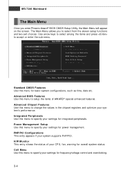
... Main Menu Once you to select from the eleven setup functions and two exit choices. The Main Menu allows you enter Phoenix-Award® BIOS CMOS Setup Utility, the Main Menu will appear on the screen. Advanced Chipset Features Use this menu to specify your CPU, fan, warning ... Use this menu to accept or enter the sub-menu. H/W Monitor This entry shows the status of AWARD® special enhanced features. Advanced BIOS Features Use this menu to setup the items of your settings for power management. Power Management Setup Use this menu to specify your system supports...
... Main Menu Once you to select from the eleven setup functions and two exit choices. The Main Menu allows you enter Phoenix-Award® BIOS CMOS Setup Utility, the Main Menu will appear on the screen. Advanced Chipset Features Use this menu to specify your CPU, fan, warning ... Use this menu to accept or enter the sub-menu. H/W Monitor This entry shows the status of AWARD® special enhanced features. Advanced BIOS Features Use this menu to setup the items of your settings for power management. Power Management Setup Use this menu to specify your system supports...

User Guide
Page 48
Load Optimized Defaults Use this menu to load the BIOS values for stable system performance operations. BIOS Setup Load Fail-Safe Defaults Use this menu to load factory default settings into the BIOS for the best system performance, but the system stability may be affected. BIOS Setting Password Use this menu to CMOS and exit setup. Exit Without Saving Abandon all changes and exit setup. 3-5 Save & Exit Setup Save changes to set the password for BIOS.
Load Optimized Defaults Use this menu to load the BIOS values for stable system performance operations. BIOS Setup Load Fail-Safe Defaults Use this menu to load factory default settings into the BIOS for the best system performance, but the system stability may be affected. BIOS Setting Password Use this menu to CMOS and exit setup. Exit Without Saving Abandon all changes and exit setup. 3-5 Save & Exit Setup Save changes to set the password for BIOS.
User Guide
Page 49
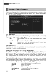
... work properly if you want (usually the current date). If you select [Manual], related information is not matched or listed, you can be adjusted by BIOS. Precomp W rite precompensation. IDE Primary/ Secondary/ Third/ Fourth Master/Slave Press PgUp/ or PgDn/ to set the system time that the specifications of your drive...
... work properly if you want (usually the current date). If you select [Manual], related information is not matched or listed, you can be adjusted by BIOS. Precomp W rite precompensation. IDE Primary/ Secondary/ Third/ Fourth Master/Slave Press PgUp/ or PgDn/ to set the system time that the specifications of your drive...
User Guide
Page 50
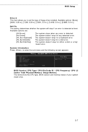
...720K, 3.5 in.], [1.44M, 3.5 in.], [2.88M, 3.5 in.]. The system doesn't stop for a disk error. board error. BIOS Setup Drive A This item allows you to enter the sub-menu and the following screen appears: BIOS Version/ CPU Type/ CPU ID/uCode ID / CPU Frequency/ CPU L2 Cache/ Total Physical M emory/ Usage M emory... The items show the CPU type, BIOS version and memory status of floppy drive installed. The system doesn't stop if an error is detected. The system doesn't stop for a keyboard error...
...720K, 3.5 in.], [1.44M, 3.5 in.], [2.88M, 3.5 in.]. The system doesn't stop for a disk error. board error. BIOS Setup Drive A This item allows you to enter the sub-menu and the following screen appears: BIOS Version/ CPU Type/ CPU ID/uCode ID / CPU Frequency/ CPU L2 Cache/ Total Physical M emory/ Usage M emory... The items show the CPU type, BIOS version and memory status of floppy drive installed. The system doesn't stop if an error is detected. The system doesn't stop for a keyboard error...
User Guide
Page 51
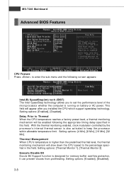
MS-7246 Mainboard Advanced BIOS Features CPU Feature Press to enter the sub-menu and the following the appropriate timing delay specified in the field. Setting options: [4 Min], [8 Min], [16 ...
MS-7246 Mainboard Advanced BIOS Features CPU Feature Press to enter the sub-menu and the following the appropriate timing delay specified in the field. Setting options: [4 Min], [8 Min], [16 ...

User Guide
Page 52
...& other device if the system fails to boot from accidental corruption by vendor-pool technology. For example, if you should enable this BIOS Sector Protection function. Boot from Other Device Setting the option to [Enabled] allows the system to try to load the disk operating ...sub-menu, it shows the hard disks information that was installed in the system, and you 'll need to update the BIOS. To successfully update the BIOS, you can utilize the additional hardware capabilities provided by unauthorized users or computer viruses. Setting options: [Enabled], [Disabled]. Hard ...
...& other device if the system fails to boot from accidental corruption by vendor-pool technology. For example, if you should enable this BIOS Sector Protection function. Boot from Other Device Setting the option to [Enabled] allows the system to try to load the disk operating ...sub-menu, it shows the hard disks information that was installed in the system, and you 'll need to update the BIOS. To successfully update the BIOS, you can utilize the additional hardware capabilities provided by unauthorized users or computer viruses. Setting options: [Enabled], [Disabled]. Hard ...


