
User Guide
Page 2
...; is the intellectual property of its contents. Visit the MSI website for further guidance. Trademarks All trademarks are registered trademarks of purchase or local distributor. Alternatively, please try the following help resources for FAQ, technical guide, BIOS updates, driver updates, and other countries. Award® is a registered trademark of International Business Machines Corporation. W indows® 95/98/2000...
...; is the intellectual property of its contents. Visit the MSI website for further guidance. Trademarks All trademarks are registered trademarks of purchase or local distributor. Alternatively, please try the following help resources for FAQ, technical guide, BIOS updates, driver updates, and other countries. Award® is a registered trademark of International Business Machines Corporation. W indows® 95/98/2000...
User Guide
Page 8
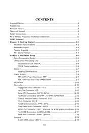
...12 Hard Disk Connector: IDE1 2-12 Serial ATA Connectors: SATA1~SATA4 2-13 Fan Power Connectors: CPUFAN1, SYSFAN1&PWRFAN1 2-14 Chassis Intrusion Switch Connector: JCI2 2-14 CD-In Connector: CD_IN1 2-15 Front Panel Connectors: JFP1 / JFP2 2-15 Front Panel Audio Connector: JAUD1 2-16 SPDIF-Out Connector: JSPD1 (Optional, for HDMI graphics card only) 2-16 Front USB Connectors: JUSB1 / JUSB2 2-17 Serial Port Connector: JCOM1 (optional 2-18 Jumpers ...2-19 Clear CMOS Jumper: JBAT1 2-19 viii Getting Started 1-1 Mainboard Specifications 1-2 Mainboard Layout 1-4 Packing Checklist 1-5 MSI...
...12 Hard Disk Connector: IDE1 2-12 Serial ATA Connectors: SATA1~SATA4 2-13 Fan Power Connectors: CPUFAN1, SYSFAN1&PWRFAN1 2-14 Chassis Intrusion Switch Connector: JCI2 2-14 CD-In Connector: CD_IN1 2-15 Front Panel Connectors: JFP1 / JFP2 2-15 Front Panel Audio Connector: JAUD1 2-16 SPDIF-Out Connector: JSPD1 (Optional, for HDMI graphics card only) 2-16 Front USB Connectors: JUSB1 / JUSB2 2-17 Serial Port Connector: JCOM1 (optional 2-18 Jumpers ...2-19 Clear CMOS Jumper: JBAT1 2-19 viii Getting Started 1-1 Mainboard Specifications 1-2 Mainboard Layout 1-4 Packing Checklist 1-5 MSI...
User Guide
Page 9
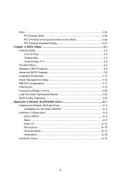
BIOS Setup 3-1 Entering Setup ...3-2 Control Keys 3-3 Getting Help 3-3 General Help Slots ...2-20 PCI Express Slots 2-20 PCI (Peripheral Component Interconnect) Slots 2-20 PCI Interrupt Request Routing 2-21 Chapter 3.
BIOS Setup 3-1 Entering Setup ...3-2 Control Keys 3-3 Getting Help 3-3 General Help Slots ...2-20 PCI Express Slots 2-20 PCI (Peripheral Component Interconnect) Slots 2-20 PCI Interrupt Request Routing 2-21 Chapter 3.
User Guide
Page 11
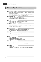
... - North Bridge: Intel® 945G/ 945GC/ 945GZ chipset - Or supports 10/100 Fast Ethermet by ICH7 - High Definition link controller integrated in the LGA775 package. Supports 1 FDD with Azalia 1.0 Spec IDE - 1 IDE port by Realtek 8101E Audio - MS-7267 Mainboard Mainboard Specifications Processor Support - Intel® Core 2 Duo/ Pentium D/ Pentium 4/ Celeron Series processors in Intel® ICH7 chip - 7.1 channels audio codec Realtek ALC883/ ALC888 - Supports storage and data transfers at up to 300MB/s Floppy - 1 floppy port -
... - North Bridge: Intel® 945G/ 945GC/ 945GZ chipset - Or supports 10/100 Fast Ethermet by ICH7 - High Definition link controller integrated in the LGA775 package. Supports 1 FDD with Azalia 1.0 Spec IDE - 1 IDE port by Realtek 8101E Audio - MS-7267 Mainboard Mainboard Specifications Processor Support - Intel® Core 2 Duo/ Pentium D/ Pentium 4/ Celeron Series processors in Intel® ICH7 chip - 7.1 channels audio codec Realtek ALC883/ ALC888 - Supports storage and data transfers at up to 300MB/s Floppy - 1 floppy port -

User Guide
Page 25
... Power Connector: PWRCONN1 This 12V power connector is also a foolproof design on pin 11, 12, 23 & 24 to avoid wrong installation. To connect the ATX 24-pin power supply, make sure the plug of the mainboard. 2. There is used to provide power to ensure stable operation of the power supply is highly recommended for system stability. 2-9 Hardware Setup Power Supply ATX 24-Pin Power Connector: ATX1 This connector allows you like to use the 20-pin ATX power supply, please plug your power supply...
... Power Connector: PWRCONN1 This 12V power connector is also a foolproof design on pin 11, 12, 23 & 24 to avoid wrong installation. To connect the ATX 24-pin power supply, make sure the plug of the mainboard. 2. There is used to provide power to ensure stable operation of the power supply is highly recommended for system stability. 2-9 Hardware Setup Power Supply ATX 24-Pin Power Connector: ATX1 This connector allows you like to use the 20-pin ATX power supply, please plug your power supply...

User Guide
Page 28
... IDE controller that supports PIO mode 0~4, Bus Master, and Ultra DMA 66/100 function. You must configure the second drive to the hard disk documentation supplied by hard disk vendors for jumper setting instructions. 2-12 MS-7267 Mainboard Connectors Floppy Disk Drive Connector: FDD2 This standard FDD connector supports 360K, 720K, 1.2M, 1.44M and 2.88M floppy disk types. Important If you install two hard disks on cable, you must configure the second hard drive to Slave mode by setting its jumper. IDE1 IDE1 IDE1 can connect hard disk drives, CD-ROM drives...
... IDE controller that supports PIO mode 0~4, Bus Master, and Ultra DMA 66/100 function. You must configure the second drive to the hard disk documentation supplied by hard disk vendors for jumper setting instructions. 2-12 MS-7267 Mainboard Connectors Floppy Disk Drive Connector: FDD2 This standard FDD connector supports 360K, 720K, 1.2M, 1.44M and 2.88M floppy disk types. Important If you install two hard disks on cable, you must configure the second hard drive to Slave mode by setting its jumper. IDE1 IDE1 IDE1 can connect hard disk drives, CD-ROM drives...

User Guide
Page 32
signals BIOS that a High Definition Audio dongle is used to connect SPDIF (Sony & Philips Digital Interconnect Format) interface for HDMI graphics card only) This connector is connected to the analog header. Left channel 10 SENSE2_RETIRN Jack detection return from the High Definition Audio CODEC jack detection resistor network 8 KEY Connector Key 9 PORT 2L Analog Port 2 - SPDF0 GND JSPD1 2-16 MS-7267 Mainboard Front Panel Audio Connector: JAUD1 The JAUD1 front panel audio connector allows you to connect the front panel audio and...
signals BIOS that a High Definition Audio dongle is used to connect SPDIF (Sony & Philips Digital Interconnect Format) interface for HDMI graphics card only) This connector is connected to the analog header. Left channel 10 SENSE2_RETIRN Jack detection return from the High Definition Audio CODEC jack detection resistor network 8 KEY Connector Key 9 PORT 2L Analog Port 2 - SPDF0 GND JSPD1 2-16 MS-7267 Mainboard Front Panel Audio Connector: JAUD1 The JAUD1 front panel audio connector allows you to connect the front panel audio and...

User Guide
Page 35
... off. Avoid clearing the CMOS while the system is a CMOS RAM onboard that has a power supply from external battery to keep the data of system configuration. If you want to clear the system configuration, set the JBAT1 (Clear CMOS Jumper ) to 1-2 pin position. Then return to clear data. 1 JBAT1 1 1 3 Keep Data 3 Clear Data Important You can automatically boot OS every time it will damage the mainboard. 2-19 Hardware Setup Jumpers Clear CMOS Jumper: JBAT1 There...
... off. Avoid clearing the CMOS while the system is a CMOS RAM onboard that has a power supply from external battery to keep the data of system configuration. If you want to clear the system configuration, set the JBAT1 (Clear CMOS Jumper ) to 1-2 pin position. Then return to clear data. 1 JBAT1 1 1 3 Keep Data 3 Clear Data Important You can automatically boot OS every time it will damage the mainboard. 2-19 Hardware Setup Jumpers Clear CMOS Jumper: JBAT1 There...
User Guide
Page 36
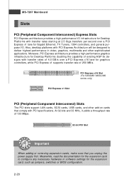
... configure any necessary hardware or software settings for Gigabit Ethernet, TV Tuners, 1394 controllers, and general purpose I/O. Moreover, PCI Express architecture provides a high performance graphics infrastructure for graphics controllers, while PCI Express x1 supports transfer rate of 133 MBps. 32-bit PCI Slot Important When adding or removing expansion cards, make sure that comply with transfer rates of 4.0 GB/s over a PCI Express x1 lane for the expansion card, such as jumpers, switches or BIOS configuration...
... configure any necessary hardware or software settings for Gigabit Ethernet, TV Tuners, 1394 controllers, and general purpose I/O. Moreover, PCI Express architecture provides a high performance graphics infrastructure for graphics controllers, while PCI Express x1 supports transfer rate of 133 MBps. 32-bit PCI Slot Important When adding or removing expansion cards, make sure that comply with transfer rates of 4.0 GB/s over a PCI Express x1 lane for the expansion card, such as jumpers, switches or BIOS configuration...

User Guide
Page 44
... mode for the IDE devices that monitors your disk status to enable or disable the DMA (Direct Memory Access) mode. S.M.A.R.T is going to fail to activate the S.M.A.R.T. (Self-Monitoring Analysis & Reporting Technology) capability for the hard disks. LBA/Large M ode This allows you to a safe place before the hard disk becomes offline. This allows you to enhance the hard disk performance. Setting options: [AUTO], [Not Insatlled], [CD/DVD], [ARMD]. Setting to Auto enables LBA mode if the device supports...
... mode for the IDE devices that monitors your disk status to enable or disable the DMA (Direct Memory Access) mode. S.M.A.R.T is going to fail to activate the S.M.A.R.T. (Self-Monitoring Analysis & Reporting Technology) capability for the hard disks. LBA/Large M ode This allows you to a safe place before the hard disk becomes offline. This allows you to enhance the hard disk performance. Setting options: [AUTO], [Not Insatlled], [CD/DVD], [ARMD]. Setting to Auto enables LBA mode if the device supports...

User Guide
Page 46
... message on screen and alarm beep. Setting to write date into this function is enabled and someone attempt to [On] will expand available IRQ resources for IDE Hard Disk boot sector protection. Advanced BIOS Features BIOS Setup Boot Sector Protection This item allows you to use the arrow keys on the numeric keypad. IOAPIC Function This field is powered on. Enabling APIC mode will turn on the Num...
... message on screen and alarm beep. Setting to write date into this function is enabled and someone attempt to [On] will expand available IRQ resources for IDE Hard Disk boot sector protection. Advanced BIOS Features BIOS Setup Boot Sector Protection This item allows you to use the arrow keys on the numeric keypad. IOAPIC Function This field is powered on. Enabling APIC mode will turn on the Num...

User Guide
Page 48
... designed to limit the listed speed of the processor to older operating systems. Chipset Feature Press to enter the sub-menu, and the following screen appears. 1st Boot Device This item allows you to set the sequence of boot device where BIOS attempts to load the disk operating system. 3-11 PEG Force X1 The field enables or disables the PEG (PCI Express Graphic) port function. VGA Share Memory The system shares memory to the VGA card.
... designed to limit the listed speed of the processor to older operating systems. Chipset Feature Press to enter the sub-menu, and the following screen appears. 1st Boot Device This item allows you to set the sequence of boot device where BIOS attempts to load the disk operating system. 3-11 PEG Force X1 The field enables or disables the PEG (PCI Express Graphic) port function. VGA Share Memory The system shares memory to the VGA card.
User Guide
Page 49
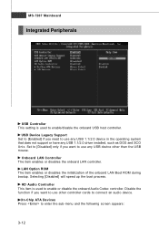
... disable the onboard Audio Codec controller. USB Device Legacy Support Set to [Enabled] if you need to use any USB 1.1/2.0 device in the operating system that does not support or have any USB device other controller cards to connect an audio device. Disable the function if you want to enter the sub-menu and the following screen appears: 3-12 MS-7267 Mainboard Integrated Peripherals USB Controller This setting is used to enable/disable the onboard USB host controller. LAN Option ROM The item enables or disables the initialization of the onboard LAN Boot ROM...
... disable the onboard Audio Codec controller. USB Device Legacy Support Set to [Enabled] if you need to use any USB 1.1/2.0 device in the operating system that does not support or have any USB device other controller cards to connect an audio device. Disable the function if you want to enter the sub-menu and the following screen appears: 3-12 MS-7267 Mainboard Integrated Peripherals USB Controller This setting is used to enable/disable the onboard USB host controller. LAN Option ROM The item enables or disables the initialization of the onboard LAN Boot ROM...
User Guide
Page 50
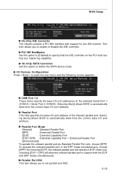
... onboard Serial Port 1 (COM A) / Serial Port 2 (COM B). Selecting [Auto] allows BIOS to enter the sub-menu and the following screen appears: COM Port 1/2 These items specify the base I /O port address. BIOS Setup On-Chip IDE Controller The chipset contains a PCI IDE interface with support for one IDE channel. Choosing [ECP + EPP] will operate in the EPP mode simultaneously, choose [EPP]. Parallel Port IRQ This item allows you to define the SATA device mode. PCI IDE BusMaster Set this option to enable or disable the IDE controller...
... onboard Serial Port 1 (COM A) / Serial Port 2 (COM B). Selecting [Auto] allows BIOS to enter the sub-menu and the following screen appears: COM Port 1/2 These items specify the base I /O port address. BIOS Setup On-Chip IDE Controller The chipset contains a PCI IDE interface with support for one IDE channel. Choosing [ECP + EPP] will operate in the EPP mode simultaneously, choose [EPP]. Parallel Port IRQ This item allows you to define the SATA device mode. PCI IDE BusMaster Set this option to enable or disable the IDE controller...
User Guide
Page 51
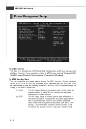
... [Enabled]. The information stored in memory will be used to activate the ACPI (Advanced Configuration and Power Management Interface) Function. Options are: S1/POS S3/STR The S1 sleep mode is lost (CPU or chipset) and hardware maintains all system context. The S3 sleep mode is to restore the system when a "wake up" event occurs. 3-14 In this field. Setting options: [Enabled] and [Disabled]. MS-7267 Mainboard Power Management Setup ACPI Function...
... [Enabled]. The information stored in memory will be used to activate the ACPI (Advanced Configuration and Power Management Interface) Function. Options are: S1/POS S3/STR The S1 sleep mode is lost (CPU or chipset) and hardware maintains all system context. The S3 sleep mode is to restore the system when a "wake up" event occurs. 3-14 In this field. Setting options: [Enabled] and [Disabled]. MS-7267 Mainboard Power Management Setup ACPI Function...

User Guide
Page 52
... the system to enter sub-menu and the following screen appears. 3-15 Settings are : [Off] Leaves the computer in the power off state. [On] Leaves the computer in this field, all devices except CPU will reboot after resuming from S3 sleep state. BIOS Setup Re-Call VGA BIOS from S3 W hen ACPI Standby State is set to initialize the VGA card when system wakes up (resumes) from...
... the system to enter sub-menu and the following screen appears. 3-15 Settings are : [Off] Leaves the computer in the power off state. [On] Leaves the computer in this field, all devices except CPU will reboot after resuming from S3 sleep state. BIOS Setup Re-Call VGA BIOS from S3 W hen ACPI Standby State is set to initialize the VGA card when system wakes up (resumes) from...

User Guide
Page 53
... type the password to power on PME (Power Management Event). Resume By RTC Alarm This is used to enable or disable the feature of the USB device to wake up the system on the system. MS-7267 Mainboard Resume From S3 By USB Device The item allows the activity of booting up the system from S3 (Suspend to RAM) sleep state. Setting options: [Disabled], [Enabled]. Resume By PCIE Device W hen setting to [Enabled], this setting...
... type the password to power on PME (Power Management Event). Resume By RTC Alarm This is used to enable or disable the feature of the USB device to wake up the system on the system. MS-7267 Mainboard Resume From S3 By USB Device The item allows the activity of booting up the system from S3 (Suspend to RAM) sleep state. Setting options: [Disabled], [Enabled]. Resume By PCIE Device W hen setting to [Enabled], this setting...

User Guide
Page 54
... the effective PCI bandwidth. Selecting [Auto] allows BIOS to higher values, every PCI device can hold the bus before another takes over. IRQ Resource Setup Press to higher values. W hen set the item to enter sub-menu and the following screen appears. 3-17 PCI Latency Timer This item controls how long each PCI device can conduct transactions for each PCI slot. PNP/PCI Configurations BIOS Setup Primary Graphic's Adapter This setting specifies which graphics adapter...
... the effective PCI bandwidth. Selecting [Auto] allows BIOS to higher values, every PCI device can hold the bus before another takes over. IRQ Resource Setup Press to higher values. W hen set the item to enter sub-menu and the following screen appears. 3-17 PCI Latency Timer This item controls how long each PCI device can conduct transactions for each PCI slot. PNP/PCI Configurations BIOS Setup Primary Graphic's Adapter This setting specifies which graphics adapter...

User Guide
Page 56
Setting options: [Enabled], [Reset], [Disabled]. CPU Smart Fan Target The mainboard provides the Smart Fan system which will automatically return to [Reset]. Smart Fan is once opened. H/W Monitor BIOS Setup Chassis Intrusion The field enables or disables the feature of recording the chassis intrusion status and issuing a warning message if the chassis is an excellent feature which can control the fan speed automatically depending on the CPU current temperature, avoiding the overheating to damage your system. The setting of...
Setting options: [Enabled], [Reset], [Disabled]. CPU Smart Fan Target The mainboard provides the Smart Fan system which will automatically return to [Reset]. Smart Fan is once opened. H/W Monitor BIOS Setup Chassis Intrusion The field enables or disables the feature of recording the chassis intrusion status and issuing a warning message if the chassis is an excellent feature which can control the fan speed automatically depending on the CPU current temperature, avoiding the overheating to damage your system. The setting of...

User Guide
Page 63
...-ROM drive. The setup screen will automatically appear. 2. Click Realtek HD Audio Driver. channel or 7.1+2 channel audio operations. Click here Important The HD Audio Configuration software utility is under continuous update to 2-, 4-, 6-, 8- A-2 Hence, the program screens shown here in different operating systems. 1. Follow the procedures described below to install the drivers for different operating systems. Installation for Windows 2000/XP For W indows® 2000, you must install W indows® 2000 Service...
...-ROM drive. The setup screen will automatically appear. 2. Click Realtek HD Audio Driver. channel or 7.1+2 channel audio operations. Click here Important The HD Audio Configuration software utility is under continuous update to 2-, 4-, 6-, 8- A-2 Hence, the program screens shown here in different operating systems. 1. Follow the procedures described below to install the drivers for different operating systems. Installation for Windows 2000/XP For W indows® 2000, you must install W indows® 2000 Service...

