User Guide
Page 11
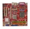
.... 10. Push down to lock the hooks. 12. However, you can barely see the golden finger if the memory module is properly inserted in the BIOS : Enter BIOS setup menu and go to [266] for demonstration of the mainboard. 11. Then push it ) to fasten the cooler. Visually inspect if the CPU... is deeply inserted in this board supports CPU of the DIMM slot will only fit in BIOS. The appearance of your board running at each side of FSB 800MHz at maximum by overclocking and adjusting the CPU FSB frequency in the DIMM...
.... 10. Push down to lock the hooks. 12. However, you can barely see the golden finger if the memory module is properly inserted in the BIOS : Enter BIOS setup menu and go to [266] for demonstration of the mainboard. 11. Then push it ) to fasten the cooler. Visually inspect if the CPU... is deeply inserted in this board supports CPU of the DIMM slot will only fit in BIOS. The appearance of your board running at each side of FSB 800MHz at maximum by overclocking and adjusting the CPU FSB frequency in the DIMM...
User Guide
Page 13
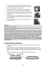
... Intel® I/O Connectivity Design Guide, is opened, the chassis intrusion mechanism will record this status and show a warning message on -board, you must enter the BIOS utility and clear the record. 1 CINTRU 2 GND 7 GND USB0+ S/PDIF-Out Connector: JSPD1 This connector is the positive and should be connected to connect S/PDIF...
... Intel® I/O Connectivity Design Guide, is opened, the chassis intrusion mechanism will record this status and show a warning message on -board, you must enter the BIOS utility and clear the record. 1 CINTRU 2 GND 7 GND USB0+ S/PDIF-Out Connector: JSPD1 This connector is the positive and should be connected to connect S/PDIF...
User Guide
Page 14
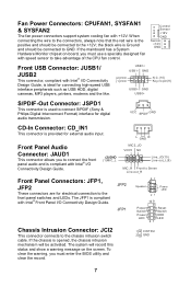
... first. it is on cards that you want to clear the system configuration, set the jumper to the PCI bus pins as jumpers, switches or BIOS configuration.
... first. it is on cards that you want to clear the system configuration, set the jumper to the PCI bus pins as jumpers, switches or BIOS configuration.
User Guide
Page 15
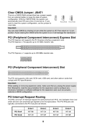
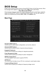
... on the computer and the system will start POST (Power On Self Test) process. H/W Monitor This entry shows the status of special enhanced features. Advanced BIOS Features Use this menu to setup the items of your system supports PnP/PCI...
... on the computer and the system will start POST (Power On Self Test) process. H/W Monitor This entry shows the status of special enhanced features. Advanced BIOS Features Use this menu to setup the items of your system supports PnP/PCI...
User Guide
Page 16
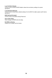
Load Fail-Safe Defaults Use this menu to load factory default settings into the BIOS for system operations. Load Optimized Defaults Use this menu to CMOS and exit setup. Exit Without Saving Abandon all changes and exit setup. 10 Save & Exit Setup Save changes to set BIOS setting Password. BIOS Setting Password Use this menu to load the BIOS default values that are factory settings for stable system performance operations.
Load Fail-Safe Defaults Use this menu to load factory default settings into the BIOS for system operations. Load Optimized Defaults Use this menu to CMOS and exit setup. Exit Without Saving Abandon all changes and exit setup. 10 Save & Exit Setup Save changes to set BIOS setting Password. BIOS Setting Password Use this menu to load the BIOS default values that are factory settings for stable system performance operations.
User Guide
Page 17
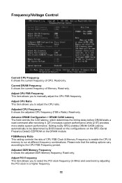
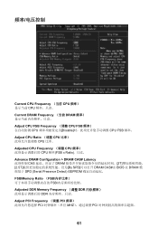
... SPD] enables DRAM CAS# Latency automatically to be determined by adjusting the PCI clock to select the PCI clock frequency (in MHz) and overclock by BIOS based on the configurations on the SPD (Serial Presence Detect) EEPROM on the DRAM module. Adjust PCI Frequency This item allows you to run at...
... SPD] enables DRAM CAS# Latency automatically to be determined by adjusting the PCI clock to select the PCI clock frequency (in MHz) and overclock by BIOS based on the configurations on the SPD (Serial Presence Detect) EEPROM on the DRAM module. Adjust PCI Frequency This item allows you to run at...

User Guide
Page 63
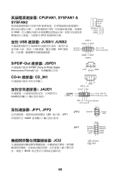
...; USB 接口: JUSB1/ JUSB2 Intel® I /O JFP2 87 Speaker 21 10 9 Power LED + -- + -+ JFP1 Power Reset Switch Switch Power HDD LED LED 21 JCI2 BIOS 1 CINTRU 2 GND 清除 CMOS 跳线: JBAT1 1 2 CMOS RAM 3 CMOS RAM CMOS RAM 1 2 3 Keep Data 1 2 3 Clear Data 注意: 2-3 CMOS 1-2 CMOS 57 GND (2)VCC...
...; USB 接口: JUSB1/ JUSB2 Intel® I /O JFP2 87 Speaker 21 10 9 Power LED + -- + -+ JFP1 Power Reset Switch Switch Power HDD LED LED 21 JCI2 BIOS 1 CINTRU 2 GND 清除 CMOS 跳线: JBAT1 1 2 CMOS RAM 3 CMOS RAM CMOS RAM 1 2 3 Keep Data 1 2 3 Clear Data 注意: 2-3 CMOS 1-2 CMOS 57 GND (2)VCC...
User Guide
Page 66
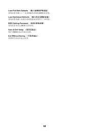
Load Fail-Safe Defaults BIOS Load Optimized Defaults BIOS Setting Password (BIOS BIOS Save & Exit Setup CMOS Exit Without Saving 60
Load Fail-Safe Defaults BIOS Load Optimized Defaults BIOS Setting Password (BIOS BIOS Save & Exit Setup CMOS Exit Without Saving 60
User Guide
Page 67
... Frequency (调整 CPU CPU 频率(FSB x Ratio Advance DRAM Configuration > DRAM CAS# Latency CAS DRAM 2T 2.5T By SPD DRAM CAS#由 BIOS 在 DRAM SPD (Serial Presence Detect) EEPROM FSB/Memory Ratio (FSB FSB Adjusted DDR Memory Frequency (调整 DDR DDR Adjust PCI Frequency...
... Frequency (调整 CPU CPU 频率(FSB x Ratio Advance DRAM Configuration > DRAM CAS# Latency CAS DRAM 2T 2.5T By SPD DRAM CAS#由 BIOS 在 DRAM SPD (Serial Presence Detect) EEPROM FSB/Memory Ratio (FSB FSB Adjusted DDR Memory Frequency (调整 DDR DDR Adjust PCI Frequency...
User Guide
Page 75
... Line-out_R JFP1, JFP2 LED JFP1 Intel JFP2 87 Speaker Power LED 21 10 9 + -- + -+ JFP1 Power Reset Switch Switch Power HDD LED LED 21 JCI2 BIOS 1 CINTRU 2 GND 69 GND (2)VCC (1)VCC N.C.(10) Key,no pin(9) USB0-
... Line-out_R JFP1, JFP2 LED JFP1 Intel JFP2 87 Speaker Power LED 21 10 9 + -- + -+ JFP1 Power Reset Switch Switch Power HDD LED LED 21 JCI2 BIOS 1 CINTRU 2 GND 69 GND (2)VCC (1)VCC N.C.(10) Key,no pin(9) USB0-
User Guide
Page 78
Load Fail-Safe Defaults BIOS Load Optimized Defaults BIOS BIOS Setting Password(設定 BIOS BIOS 密碼。 Save & Exit Setup CMOS Exit Without Saving 72
Load Fail-Safe Defaults BIOS Load Optimized Defaults BIOS BIOS Setting Password(設定 BIOS BIOS 密碼。 Save & Exit Setup CMOS Exit Without Saving 72
User Guide
Page 91
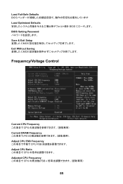
Load Fail-Safe Defaults BIOS Load Optimized Defaults BIOS BIOS Setting Password Save & Exit Setup CMOS Exit Without Saving CMOS Frequency/Voltage Control Current CPU Frequency CPU Current DRAM Frequency Adjust CPU FSB Frequency CPU FSB Adjust CPU Ratio CPU Adjusted CPU Frequency CPU FSB x 85
Load Fail-Safe Defaults BIOS Load Optimized Defaults BIOS BIOS Setting Password Save & Exit Setup CMOS Exit Without Saving CMOS Frequency/Voltage Control Current CPU Frequency CPU Current DRAM Frequency Adjust CPU FSB Frequency CPU FSB Adjust CPU Ratio CPU Adjusted CPU Frequency CPU FSB x 85


