
User Guide
Page 1
... the user's authority to operate the equipment. Micro-Star International MS-7267 However, there is connected. Notice 2 Shielded interface cables and A.C. n Connect the equipment into an outlet on , the user is ...installed and used in order to provide reasonable protection against harmful interference in accordance with the limits for a class B digital device, pursuant to part 15 of the measures listed below. n Reorient or relocate the receiving antenna. n Increase the separation between the equipment and receiver. VOIR LA NOTICE D'NSTALLATION AVANT DE RACCORDER AU RESEAU. power...
... the user's authority to operate the equipment. Micro-Star International MS-7267 However, there is connected. Notice 2 Shielded interface cables and A.C. n Connect the equipment into an outlet on , the user is ...installed and used in order to provide reasonable protection against harmful interference in accordance with the limits for a class B digital device, pursuant to part 15 of the measures listed below. n Reorient or relocate the receiving antenna. n Increase the separation between the equipment and receiver. VOIR LA NOTICE D'NSTALLATION AVANT DE RACCORDER AU RESEAU. power...
User Guide
Page 2
...International Business Machines Corporation. PCMCIA and CardBus are registered trademarks of the Kensington Technology Group. Revision History Revision Revision History V4.1 Release for 945GCM5 V2 series (Intel 945GC & ICH7) Date April, 2007 Copyright Notice The material in this document, but no guarantee is given as to make changes...this document is the intellectual property of the Personal Computer Memory Card International Association. PS/2 and OS®/2 are registered trademarks of MICRO-STAR INTERNATIONAL. Microsoft® is a registered trademark of Microsoft ...
...International Business Machines Corporation. PCMCIA and CardBus are registered trademarks of the Kensington Technology Group. Revision History Revision Revision History V4.1 Release for 945GCM5 V2 series (Intel 945GC & ICH7) Date April, 2007 Copyright Notice The material in this document, but no guarantee is given as to make changes...this document is the intellectual property of the Personal Computer Memory Card International Association. PS/2 and OS®/2 are registered trademarks of MICRO-STAR INTERNATIONAL. Microsoft® is a registered trademark of Microsoft ...
User Guide
Page 3
... openings. n Place the power cord such a way that could damage or cause electrical shock. The equipment does not work according to User Manual. - n The openings on the equipment should be noted. n Never pour any liquid into the equipment. - Replace only with the same or equivalent type recommended by a service personnel: - Safety Instructions n Always read the safety instructions carefully. n Keep...
... openings. n Place the power cord such a way that could damage or cause electrical shock. The equipment does not work according to User Manual. - n The openings on the equipment should be noted. n Never pour any liquid into the equipment. - Replace only with the same or equivalent type recommended by a service personnel: - Safety Instructions n Always read the safety instructions carefully. n Keep...
User Guide
Page 7
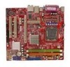
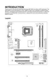
....x) Micro-ATX mainboard. Designed to fit the advanced Intel® Core2 Duo/ Pentium D/ Pentium 4 / Celeron D processor, the 945GCM5 V2 series deliver a high performance and professional desktop platform solution. Layout Top : mouse Bottom: keyboard CPUFAN1 DIMM1 DIMM2 Top : Parallel Port Bottom: COM Port VGA Port ATX1 USB ports PWRCONN1 T: LAN jack B: USB ports T:Line -I n M:Line-Out B:Mic JCI2 T:RS-Ou t (opti onal) I/O Chip M:CS-Out (optional) B:SS-Out (o ptio nal) LAN Chip PCI_E1 PCI_E2 AUDIO Chip PCI2...
....x) Micro-ATX mainboard. Designed to fit the advanced Intel® Core2 Duo/ Pentium D/ Pentium 4 / Celeron D processor, the 945GCM5 V2 series deliver a high performance and professional desktop platform solution. Layout Top : mouse Bottom: keyboard CPUFAN1 DIMM1 DIMM2 Top : Parallel Port Bottom: COM Port VGA Port ATX1 USB ports PWRCONN1 T: LAN jack B: USB ports T:Line -I n M:Line-Out B:Mic JCI2 T:RS-Ou t (opti onal) I/O Chip M:CS-Out (optional) B:SS-Out (o ptio nal) LAN Chip PCI_E1 PCI_E2 AUDIO Chip PCI2...
User Guide
Page 8
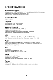
...?func=testreport) LAN l Supports 10/100 Mb/s Fast Ethernet by Realtek RTL 8101E l Or Supports 10/100/1000 Mb/s Fast Ethermet by Realtek RTL 8111B Audio l Chip integrated by Realtek ALC883, supports HD 5.1-channel audio-out l Or chip integrated by Realtek ALC888, supports HD 7.1-channel audio-out l Vista Premium compliance IDE l 1 IDE port l Supports Ultra DMA 66/100 mode l Supports PIO, Bus Master operation mode SATA l 4 SATA ports by ICH7 chipset l Supports 4 SATA devices l Supports storage and data transfers...
...?func=testreport) LAN l Supports 10/100 Mb/s Fast Ethernet by Realtek RTL 8101E l Or Supports 10/100/1000 Mb/s Fast Ethermet by Realtek RTL 8111B Audio l Chip integrated by Realtek ALC883, supports HD 5.1-channel audio-out l Or chip integrated by Realtek ALC888, supports HD 7.1-channel audio-out l Vista Premium compliance IDE l 1 IDE port l Supports Ultra DMA 66/100 mode l Supports PIO, Bus Master operation mode SATA l 4 SATA ports by ICH7 chipset l Supports 4 SATA devices l Supports storage and data transfers...
User Guide
Page 9
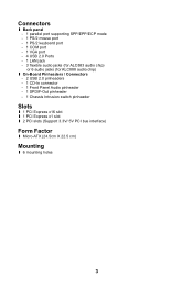
Connectors l Back panel - 1 parallel port supporting SPP/EPP/ECP mode - 1 PS/2 mouse port - 1 PS/2 keyboard port - 1 COM port - 1 VGA port - 4 USB 2.0 Ports - 1 LAN jack - 3 flexible audio jacks (for ALC883 audio chip) or 6 audio jacks (for ALC888 audio chip) l On-Board Pinheaders / Connectors - 2 USB 2.0 pinheaders - 1 CD-In connector - 1 Front Panel Audio pinheader - 1 SPDIF-Out pinheader - 1 Chassis Intrusion switch pinheader Slots l 1 PCI Express x16 slot l 1 PCI Express x1 slot l 2 PCI slots (Support 3.3V/ 5V PCI bus interface) Form Factor l Micro-ATX (24.5cm X 22.5 cm) Mounting l 6 ...
Connectors l Back panel - 1 parallel port supporting SPP/EPP/ECP mode - 1 PS/2 mouse port - 1 PS/2 keyboard port - 1 COM port - 1 VGA port - 4 USB 2.0 Ports - 1 LAN jack - 3 flexible audio jacks (for ALC883 audio chip) or 6 audio jacks (for ALC888 audio chip) l On-Board Pinheaders / Connectors - 2 USB 2.0 pinheaders - 1 CD-In connector - 1 Front Panel Audio pinheader - 1 SPDIF-Out pinheader - 1 Chassis Intrusion switch pinheader Slots l 1 PCI Express x16 slot l 1 PCI Express x1 slot l 2 PCI slots (Support 3.3V/ 5V PCI bus interface) Form Factor l Micro-ATX (24.5cm X 22.5 cm) Mounting l 6 ...
User Guide
Page 10
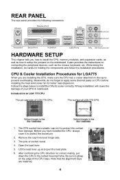
... LGA 775 CPU The pin-pad side of your CPU & mainboard. Introduction to install the CPU & cooler correctly. Open the load lever. 5. While doing the installation, be careful in the socket housing frame. REAR PANEL The rear panel provides the following connectors: Mouse Parallel Port LAN Li ne-In RS-Out(optional) Li ne-Out CS-Out(optional) Key boa rd Serial Port VGA Port USB Ports Mic SS-Out(optional) HARDWARE SETUP This chapter...
... LGA 775 CPU The pin-pad side of your CPU & mainboard. Introduction to install the CPU & cooler correctly. Open the load lever. 5. While doing the installation, be careful in the socket housing frame. REAR PANEL The rear panel provides the following connectors: Mouse Parallel Port LAN Li ne-In RS-Out(optional) Li ne-Out CS-Out(optional) Key boa rd Serial Port VGA Port USB Ports Mic SS-Out(optional) HARDWARE SETUP This chapter...
User Guide
Page 11
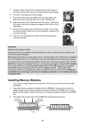
... the CPU status in the DIMM slot. 3. The plastic clip at maximum by overclocking and adjusting the CPU FSB frequency in the BIOS : Enter BIOS setup menu and go to fasten the cooler. 7. Installing Memory Modules 1. Visually inspect if the CPU is deeply inserted in the right orientation. 2. Push down to [Frequency/ Voltage Control]à[Adjust CPU FSB Frequency]. According to the Intel North Bridge 945GC chipset spec, this board supports CPU of...
... the CPU status in the DIMM slot. 3. The plastic clip at maximum by overclocking and adjusting the CPU FSB frequency in the BIOS : Enter BIOS setup menu and go to fasten the cooler. 7. Installing Memory Modules 1. Visually inspect if the CPU is deeply inserted in the right orientation. 2. Push down to [Frequency/ Voltage Control]à[Adjust CPU FSB Frequency]. According to the Intel North Bridge 945GC chipset spec, this board supports CPU of...
User Guide
Page 12
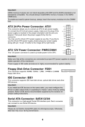
... of the mainboard. If you must configure the drives to cable select mode or separately to one Serial ATA device. Important: Please do not fold the Serial ATA cable into 90-degree angle. To connect the ATX 24-pin power supply, make sure the plug of the power supply is not backwards compatible. IDE Connector: IDE1 This connector supports IDE hard disk drives, optical disk drives and other IDE devices. Otherwise, data loss may use the 20-pin ATX power supply, please plug your power supply along with...
... of the mainboard. If you must configure the drives to cable select mode or separately to one Serial ATA device. Important: Please do not fold the Serial ATA cable into 90-degree angle. To connect the ATX 24-pin power supply, make sure the plug of the power supply is not backwards compatible. IDE Connector: IDE1 This connector supports IDE hard disk drives, optical disk drives and other IDE devices. Otherwise, data loss may use the 20-pin ATX power supply, please plug your power supply along with...
User Guide
Page 13
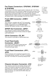
... -board, you must enter the BIOS utility and clear the record. 1 CINTRU 2 GND 7 L GND R Front Panel Audio Connector: JAUD1 This connector allows you must use a specially designed fan with Intel® I/O Connectivity Design Guide, is Ground and should be connected to the front panel switches and LEDs. JFP2 JFP1 87 Speaker Power LED 21 10 9 + -- + -+ Power Reset Switch Switch Power HDD LED LED 21 Chassis Intrusion Connector: JCI2 This connector connects to take advantage of the CPU fan control. If the chassis is provided for connecting high-speed USB interface...
... -board, you must enter the BIOS utility and clear the record. 1 CINTRU 2 GND 7 L GND R Front Panel Audio Connector: JAUD1 This connector allows you must use a specially designed fan with Intel® I/O Connectivity Design Guide, is Ground and should be connected to the front panel switches and LEDs. JFP2 JFP1 87 Speaker Power LED 21 10 9 + -- + -+ Power Reset Switch Switch Power HDD LED LED 21 Chassis Intrusion Connector: JCI2 This connector connects to take advantage of the CPU fan control. If the chassis is provided for connecting high-speed USB interface...
User Guide
Page 14
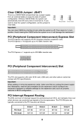
... typically connected to 4.0 GB/s transfer rate. PCI (Peripheral Component Interconnect) Express Slot The PCI Express slot supports the PCI Express interface expansion card. Clear CMOS Jumper: JBAT1 There is turned on. it is a CMOS RAM onboard that has a power supply from an external battery to 1-2 pin position. PCI (Peripheral Component Interconnect) Slot The PCI slot supports LAN card, SCSI card, USB card, and other add-on ; PCI Interrupt Request Routing The IRQ, acronym of system configuration. With the CMOS RAM, the system can clear CMOS by shorting 2-3 pin while the...
... typically connected to 4.0 GB/s transfer rate. PCI (Peripheral Component Interconnect) Express Slot The PCI Express slot supports the PCI Express interface expansion card. Clear CMOS Jumper: JBAT1 There is turned on. it is a CMOS RAM onboard that has a power supply from an external battery to 1-2 pin position. PCI (Peripheral Component Interconnect) Slot The PCI slot supports LAN card, SCSI card, USB card, and other add-on ; PCI Interrupt Request Routing The IRQ, acronym of system configuration. With the CMOS RAM, the system can clear CMOS by shorting 2-3 pin while the...
User Guide
Page 15
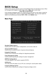
... still wish to enter Setup. Power Management Setup Use this menu to specify your settings for power management. PNP/PCI Configurations This entry appears if your CPU, fan, warning for overall system status. You may also restart the system by turning it OFF and On or pressing the RESET button. H/W Monitor This entry shows the status of special enhanced features. BIOS Setup Power on the screen, press key to enter Setup, restart the...
... still wish to enter Setup. Power Management Setup Use this menu to specify your settings for power management. PNP/PCI Configurations This entry appears if your CPU, fan, warning for overall system status. You may also restart the system by turning it OFF and On or pressing the RESET button. H/W Monitor This entry shows the status of special enhanced features. BIOS Setup Power on the screen, press key to enter Setup, restart the...
User Guide
Page 16
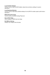
Save & Exit Setup Save changes to load the BIOS default values that are factory settings for stable system performance operations. Exit Without Saving Abandon all changes and exit setup. 10 Load Optimized Defaults Use this menu to load factory default settings into the BIOS for system operations. BIOS Setting Password Use this menu to set BIOS setting Password. Load Fail-Safe Defaults Use this menu to CMOS and exit setup.
Save & Exit Setup Save changes to load the BIOS default values that are factory settings for stable system performance operations. Exit Without Saving Abandon all changes and exit setup. 10 Load Optimized Defaults Use this menu to load factory default settings into the BIOS for system operations. BIOS Setting Password Use this menu to set BIOS setting Password. Load Fail-Safe Defaults Use this menu to CMOS and exit setup.
User Guide
Page 17
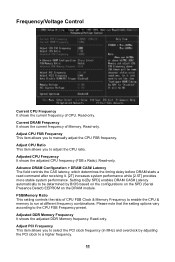
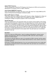
... enable the CPU & memory to the CPU FSB Frequency preset. Adjust PCI Frequency This item allows you to manually adjust the CPU FSB frequency. Frequency/Voltage Control Current CPU Frequency It shows the current frequency of Memory. Adjusted CPU Frequency It shows the adjusted CPU frequency (FSB x Ratio). Read-only. Read-only. Current DRAM Frequency It shows the current frequency of CPU. Adjust CPU Ratio This item allows you to select the PCI clock frequency (in MHz) and overclock by BIOS...
... enable the CPU & memory to the CPU FSB Frequency preset. Adjust PCI Frequency This item allows you to manually adjust the CPU FSB frequency. Frequency/Voltage Control Current CPU Frequency It shows the current frequency of Memory. Adjusted CPU Frequency It shows the adjusted CPU frequency (FSB x Ratio). Read-only. Read-only. Current DRAM Frequency It shows the current frequency of CPU. Adjust CPU Ratio This item allows you to select the PCI clock frequency (in MHz) and overclock by BIOS...
User Guide
Page 18
... voltage can introduce a temporary boost in clock speed which may just cause your overclocked processor to a higher frequency. The Spread Spectrum function reduces the EMI generated by EMI, set to adjust the Memory/PCI Express voltage. Important: If you do not have any EMI problem, leave the setting at [Disabled] for long-term purpose is reduced, and the system will remove (turn off) clocks from empty DIMM and PCI slots...
... voltage can introduce a temporary boost in clock speed which may just cause your overclocked processor to a higher frequency. The Spread Spectrum function reduces the EMI generated by EMI, set to adjust the Memory/PCI Express voltage. Important: If you do not have any EMI problem, leave the setting at [Disabled] for long-term purpose is reduced, and the system will remove (turn off) clocks from empty DIMM and PCI slots...

User Guide
Page 63
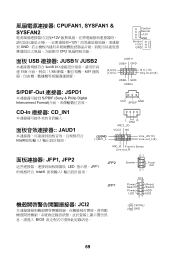
前置 USB 接口: JUSB1/ JUSB2 Intel® I /O JFP2 87 Speaker 21 10 9 Power LED + -- + -+ JFP1 Power Reset Switch Switch Power HDD LED LED 21 JCI2 BIOS 1 CINTRU 2 GND 清除 CMOS 跳线: JBAT1 1 2 CMOS RAM 3 CMOS RAM CMOS RAM 1 2 3 Keep Data 1 2 3 Clear Data 注意: 2-3 CMOS 1-2 CMOS 57 GND (2)VCC (1)VCC N.C.(10) Key,no pin(9) USB0- GND USB0+ S/PDIF-Out 接口: JSPD1 S/PDIF (Sony & Philips HDMI VCC SPDIF GND CD-In 接口: CD_IN1...
前置 USB 接口: JUSB1/ JUSB2 Intel® I /O JFP2 87 Speaker 21 10 9 Power LED + -- + -+ JFP1 Power Reset Switch Switch Power HDD LED LED 21 JCI2 BIOS 1 CINTRU 2 GND 清除 CMOS 跳线: JBAT1 1 2 CMOS RAM 3 CMOS RAM CMOS RAM 1 2 3 Keep Data 1 2 3 Clear Data 注意: 2-3 CMOS 1-2 CMOS 57 GND (2)VCC (1)VCC N.C.(10) Key,no pin(9) USB0- GND USB0+ S/PDIF-Out 接口: JSPD1 S/PDIF (Sony & Philips HDMI VCC SPDIF GND CD-In 接口: CD_IN1...
User Guide
Page 66
Load Fail-Safe Defaults BIOS Load Optimized Defaults BIOS Setting Password (BIOS BIOS Save & Exit Setup CMOS Exit Without Saving 60
Load Fail-Safe Defaults BIOS Load Optimized Defaults BIOS Setting Password (BIOS BIOS Save & Exit Setup CMOS Exit Without Saving 60
User Guide
Page 75
... 87 Speaker Power LED 21 10 9 + -- + -+ JFP1 Power Reset Switch Switch Power HDD LED LED 21 JCI2 BIOS 1 CINTRU 2 GND 69 CPUFAN1, SYSFAN1 & SYSFAN2 12V 12V GND CPU Control Sensor +12V GND Sensor +12V GND 面板 USB 連接器: JUSB1/ JUSB2 Intel® I/O USB USB MP3 S/PDIF-Out 連接器: JSPD1 S/PDIF (Sony & Philip Digital Interconnect Format USB1+ USB1- GND (2)VCC (1)VCC N.C.(10) Key,no pin...
... 87 Speaker Power LED 21 10 9 + -- + -+ JFP1 Power Reset Switch Switch Power HDD LED LED 21 JCI2 BIOS 1 CINTRU 2 GND 69 CPUFAN1, SYSFAN1 & SYSFAN2 12V 12V GND CPU Control Sensor +12V GND Sensor +12V GND 面板 USB 連接器: JUSB1/ JUSB2 Intel® I/O USB USB MP3 S/PDIF-Out 連接器: JSPD1 S/PDIF (Sony & Philip Digital Interconnect Format USB1+ USB1- GND (2)VCC (1)VCC N.C.(10) Key,no pin...

User Guide
Page 78
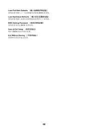
Load Fail-Safe Defaults BIOS Load Optimized Defaults BIOS BIOS Setting Password(設定 BIOS BIOS 密碼。 Save & Exit Setup CMOS Exit Without Saving 72
Load Fail-Safe Defaults BIOS Load Optimized Defaults BIOS BIOS Setting Password(設定 BIOS BIOS 密碼。 Save & Exit Setup CMOS Exit Without Saving 72
User Guide
Page 91
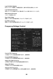
Load Fail-Safe Defaults BIOS Load Optimized Defaults BIOS BIOS Setting Password Save & Exit Setup CMOS Exit Without Saving CMOS Frequency/Voltage Control Current CPU Frequency CPU Current DRAM Frequency Adjust CPU FSB Frequency CPU FSB Adjust CPU Ratio CPU Adjusted CPU Frequency CPU FSB x 85
Load Fail-Safe Defaults BIOS Load Optimized Defaults BIOS BIOS Setting Password Save & Exit Setup CMOS Exit Without Saving CMOS Frequency/Voltage Control Current CPU Frequency CPU Current DRAM Frequency Adjust CPU FSB Frequency CPU FSB Adjust CPU Ratio CPU Adjusted CPU Frequency CPU FSB x 85

