
User Guide
Page 4
.... † The equipment has not work well or you can not step on the enclosure are for technical guide, BIOS updates, driver updates, and other information: http://www.msi.com.tw & http://www. Lay this User's Manual for future reference. 3. Make sure the voltage of the power...8224; The equipment has dropped and damaged. † The equipment has obvious sign of the following help resources for further guidance. † Visit the MSI homepage & FAQ site for air convection hence protects the equipment from humidity. 4. Keep this equipment on card or module. 9. cal shock. 11. ...
.... † The equipment has not work well or you can not step on the enclosure are for technical guide, BIOS updates, driver updates, and other information: http://www.msi.com.tw & http://www. Lay this User's Manual for future reference. 3. Make sure the voltage of the power...8224; The equipment has dropped and damaged. † The equipment has obvious sign of the following help resources for further guidance. † Visit the MSI homepage & FAQ site for air convection hence protects the equipment from humidity. 4. Keep this equipment on card or module. 9. cal shock. 11. ...

User Guide
Page 6
...2-23 PCI Interrupt Request Routing 2-23 Chapter 3. BIOS Setup 3-1 Entering Setup 3-2 Selecting the First Boot Device 3-2 Control Keys 3-2 Getting Help 3-2 Main Menu 3-2 Default Settings 3-2 The Main Menu 3-3 Standard CMOS Features 3-6 Advanced BIOS Features 3-8 Advanced Chipset Features 3-11 Integrated Peripherals... 3-12 Power Management Features 3-15 PNP/PCI Configurations 3-18 H/W Monitor 3-20 Cell Menu 3-22 BIOS Setting Password 3-24 Load Fail-Safe/Optimized Defaults 3-25 Chapter 4. Itroduction to Realtek ALC880 4-1 Installing the Realtek HD...
...2-23 PCI Interrupt Request Routing 2-23 Chapter 3. BIOS Setup 3-1 Entering Setup 3-2 Selecting the First Boot Device 3-2 Control Keys 3-2 Getting Help 3-2 Main Menu 3-2 Default Settings 3-2 The Main Menu 3-3 Standard CMOS Features 3-6 Advanced BIOS Features 3-8 Advanced Chipset Features 3-11 Integrated Peripherals... 3-12 Power Management Features 3-15 PNP/PCI Configurations 3-18 H/W Monitor 3-20 Cell Menu 3-22 BIOS Setting Password 3-24 Load Fail-Safe/Optimized Defaults 3-25 Chapter 4. Itroduction to Realtek ALC880 4-1 Installing the Realtek HD...
User Guide
Page 10
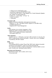
... controller integrated in ICH6 † Realtek ALC 880 8 channels (HDA) audio codec - Transfer rate is supported by VIA 6307 chipset BIOS † 4Mb FWH † The mainboard BIOS provides "Plug & Play" BIOS which detects the peripheral devices and expansion cards of the board automatically † The mainboard provides a Desktop Management Interface (DMI) function...
... controller integrated in ICH6 † Realtek ALC 880 8 channels (HDA) audio codec - Transfer rate is supported by VIA 6307 chipset BIOS † 4Mb FWH † The mainboard BIOS provides "Plug & Play" BIOS which detects the peripheral devices and expansion cards of the board automatically † The mainboard provides a Desktop Management Interface (DMI) function...
User Guide
Page 18
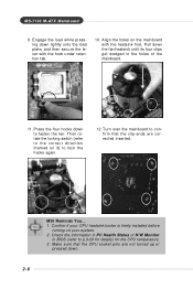
... lock the hooks again. 12. Align the holes on your system. 2. Turn over the mainboard to p.3-20 for details) for the CPU temperature. 3. locking switch MSI Reminds You... 1. Check the information in PC Health Status of H/W Monitor in the holes of the mainboard. 11. Press the four hooks down . 2-6 Then rotate... the mainboard with the hook under retention tab. 10. Engage the load while pressing down the fan/heatsink until its four clips get wedged in BIOS (refer to confirm that the CPU socket pins are corrected inserted.
... lock the hooks again. 12. Align the holes on your system. 2. Turn over the mainboard to p.3-20 for details) for the CPU temperature. 3. locking switch MSI Reminds You... 1. Check the information in PC Health Status of H/W Monitor in the holes of the mainboard. 11. Press the four hooks down . 2-6 Then rotate... the mainboard with the hook under retention tab. 10. Engage the load while pressing down the fan/heatsink until its four clips get wedged in BIOS (refer to confirm that the CPU socket pins are corrected inserted.

User Guide
Page 27
.... Chassis Intrusion Switch Connector: JCASE1 This connector is opened, the switch will record this status and show a warning message on cable, you must enter the BIOS utility and clear the record. 2 GND CINTRU 1 JCASE1 2-15 The system will be connected to Slave mode by setting its jumper. If you must configure...
.... Chassis Intrusion Switch Connector: JCASE1 This connector is opened, the switch will record this status and show a warning message on cable, you must enter the BIOS utility and clear the record. 2 GND CINTRU 1 JCASE1 2-15 The system will be connected to Slave mode by setting its jumper. If you must configure...
User Guide
Page 30
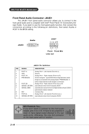
...Right channel (Front line-out R) 6 SENSE1_RETIRN Jack detection return from front panel JACK1 7 SENSE_SEND Jack detection sense line from front panel JACK2 2-18 MSI Reminds You... Left channel (Front mic L) 2 GND Ground 3 PORT 1R Analog Port 1 - PRESENCE# = 0 when a High Definition Audio ... KEY Connector Key 9 PORT 2L Analog Port 2 - Otherwise, the Line-Out connector on the back panel will not function. 6 10 59 signals BIOS that a High Definition Audio dongle is connected to the front panel audio and is connected. 5 PORT 2R Analog Port 2 - M S-7133 M ...
...Right channel (Front line-out R) 6 SENSE1_RETIRN Jack detection return from front panel JACK1 7 SENSE_SEND Jack detection sense line from front panel JACK2 2-18 MSI Reminds You... Left channel (Front mic L) 2 GND Ground 3 PORT 1R Analog Port 1 - PRESENCE# = 0 when a High Definition Audio ... KEY Connector Key 9 PORT 2L Analog Port 2 - Otherwise, the Line-Out connector on the back panel will not function. 6 10 59 signals BIOS that a High Definition Audio dongle is connected to the front panel audio and is connected. 5 PORT 2R Analog Port 2 - M S-7133 M ...
User Guide
Page 32
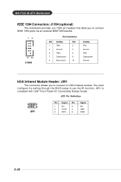
... power Ground IrDA Infrared Module Header: JIR1 The connector allows you to connect to use the IR function. You must configure the setting through the BIOS setup to IrDA Infrared module.
... power Ground IrDA Infrared Module Header: JIR1 The connector allows you to connect to use the IR function. You must configure the setting through the BIOS setup to IrDA Infrared module.

User Guide
Page 33
... use the JBAT1 (Clear CMOS Jumper ) to clear data. Then return to clear the data: 1 JBAT1 1 3 Keep Data 1 3 Clear Data MSI Reminds You... If you to set the computer's function. Avoid clearing the CMOS while the system is a CMOS RAM on . it is turned on ... to clear the system configuration, use of jumpers. W hen locked, the BIOS boot block area cannot be updated. You can be updated. 1 1 1 BIOS_WP 3 3 BIOS Flash Locked BIOS Flash Unlocked Clear CMOS Jumper: JBAT1 There is on BIOS. Follow the instructions below to 1-2 pin position. This section will damage the...
... use the JBAT1 (Clear CMOS Jumper ) to clear data. Then return to clear the data: 1 JBAT1 1 3 Keep Data 1 3 Clear Data MSI Reminds You... If you to set the computer's function. Avoid clearing the CMOS while the system is a CMOS RAM on . it is turned on ... to clear the system configuration, use of jumpers. W hen locked, the BIOS boot block area cannot be updated. You can be updated. 1 1 1 BIOS_WP 3 3 BIOS Flash Locked BIOS Flash Unlocked Clear CMOS Jumper: JBAT1 There is on BIOS. Follow the instructions below to 1-2 pin position. This section will damage the...
User Guide
Page 35
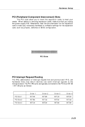
The PCI IRQ pins are hardware lines over which devices can send interrupt signals to the PCI bus INT A# ~ INT D# pins as jumpers, switches or BIOS configuration. PCI Slots PCI Interrupt Request Routing The IRQ, abbreviation of interrupt request line and pronounced I-R-Q, are typically connected to the microprocessor. Hardware Setup PCI (...
The PCI IRQ pins are hardware lines over which devices can send interrupt signals to the PCI bus INT A# ~ INT D# pins as jumpers, switches or BIOS configuration. PCI Slots PCI Interrupt Request Routing The IRQ, abbreviation of interrupt request line and pronounced I-R-Q, are typically connected to the microprocessor. Hardware Setup PCI (...
User Guide
Page 36
MSI Reminds You... 1. The items under continuous update for optimum use. While booting up , and requests you to the date this chap- W=AWARD(R) 2nd - 5th digit refers to the model number. 6th - 7th digit refers to BIOS maker as A=AMI(R); It is released. 3-1 V1.0BH refers to the BIOS version. 01/23/... the format: example: A7133IMS V1.0BH 01/23/05 where: 1st digit refers to the customer, MS=all standard customers. ter are under each BIOS category described in the 1st line appearing after the memory count. Therefore, the description may need to run the Setup program when: ² An ...
MSI Reminds You... 1. The items under continuous update for optimum use. While booting up , and requests you to the date this chap- W=AWARD(R) 2nd - 5th digit refers to the model number. 6th - 7th digit refers to BIOS maker as A=AMI(R); It is released. 3-1 V1.0BH refers to the BIOS version. 01/23/... the format: example: A7133IMS V1.0BH 01/23/05 where: 1st digit refers to the customer, MS=all standard customers. ter are under each BIOS category described in the 1st line appearing after the memory count. Therefore, the description may need to run the Setup program when: ² An ...

User Guide
Page 37
...You are allowed to enter Setup. W hen the message below appears on the screen, press key to select the 1st boot device without entering the BIOS setup utility by pressing . Select the one you power on the system, it will still use the original first boot device to enter Setup, restart... from the selected device. If so, restart the system and press after around 2 or 3 seconds to activate the boot menu similar to respond in the BIOS setup utility, so next time when you want to trigger the boot menu. M S-7133 M -ATX M ainboard Entering Setup Power on the computer and the ...
...You are allowed to enter Setup. W hen the message below appears on the screen, press key to select the 1st boot device without entering the BIOS setup utility by pressing . Select the one you power on the system, it will still use the original first boot device to enter Setup, restart... from the selected device. If so, restart the system and press after around 2 or 3 seconds to activate the boot menu similar to respond in the BIOS setup utility, so next time when you want to trigger the boot menu. M S-7133 M -ATX M ainboard Entering Setup Power on the computer and the ...
User Guide
Page 38
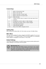
... may be held for the selected setup category is the Main Menu. Default Settings The preset Optimal Defaults of the BIOS setup program provide optimal performance settings for better system performance. MSI Reminds You... The items under continuous update for all the CMOS changes and exit Getting Help After entering the Setup...
... may be held for the selected setup category is the Main Menu. Default Settings The preset Optimal Defaults of the BIOS setup program provide optimal performance settings for better system performance. MSI Reminds You... The items under continuous update for all the CMOS changes and exit Getting Help After entering the Setup...
User Guide
Page 39
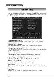
... the sub-menu. M S-7133 M -ATX M ainboard The Main Menu Once you enter AMIBIOS NEW SETUP UTILITY, the Main Menu will appear on the screen. Advanced BIOS Features Use this menu for overall system status.
... the sub-menu. M S-7133 M -ATX M ainboard The Main Menu Once you enter AMIBIOS NEW SETUP UTILITY, the Main Menu will appear on the screen. Advanced BIOS Features Use this menu for overall system status.
User Guide
Page 40
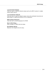
Load Optimized Defaults Use this menu to load the default values set by the BIOS vendor for stable system performance. BIOS Setting Password Use this menu to load the default values set by the mainboard manufacturer specifically for BIOS. BIOS Setup Load Fail-Safe Defaults Use this menu to set the password for optimal performance of the mainboard. Exit Without Saving Abandon all changes and exit setup. 3-5 Save & Exit Setup Save changes to CMOS and exit setup.
Load Optimized Defaults Use this menu to load the default values set by the BIOS vendor for stable system performance. BIOS Setting Password Use this menu to load the default values set by the mainboard manufacturer specifically for BIOS. BIOS Setup Load Fail-Safe Defaults Use this menu to set the password for optimal performance of the mainboard. Exit Without Saving Abandon all changes and exit setup. 3-5 Save & Exit Setup Save changes to CMOS and exit setup.
User Guide
Page 41
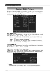
... hard disk drive will show up on the right hand according to select the hard disk drive type. year The year can be adjusted by BIOS. date The date from Jan.
... hard disk drive will show up on the right hand according to select the hard disk drive type. year The year can be adjusted by BIOS. date The date from Jan.
User Guide
Page 42
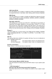
System Information Press to for a keyboard error. BIOS Setup LBA/Large Mode This item allows you an opportunity to move data from a hard disk that monitors your system (read only). 3-7 Settings: [Auto], [Enabled], [... system will stop for the hard disks. The system doesn't stop for the sub-menu of each item: Total System M emory/BIOS Version This item shows the memory status and BIOS version of your system (read only). **CPU Information** Genuine Intel (R)/CPU ID/uCode ID/CPU Frequency The three items show the...
System Information Press to for a keyboard error. BIOS Setup LBA/Large Mode This item allows you an opportunity to move data from a hard disk that monitors your system (read only). 3-7 Settings: [Auto], [Enabled], [... system will stop for the hard disks. The system doesn't stop for the sub-menu of each item: Total System M emory/BIOS Version This item shows the memory status and BIOS version of your system (read only). **CPU Information** Genuine Intel (R)/CPU ID/uCode ID/CPU Frequency The three items show the...
User Guide
Page 43
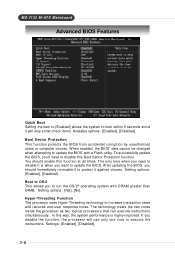
... end-user response times. In this way, the system performance is when you need to disable this function at all times. After updating the BIOS, you disable the function, the processor will skip some check items. Available options: [Enabled], [Disabled]. Boot to OS/2 This allows you ...'ll need to disable it is highly improved. To successfully update the BIOS, you to run the OS/2® operating system with a Flash utility. The technology treats the two cores inside the processor as two logical processors...
... end-user response times. In this way, the system performance is when you need to disable this function at all times. After updating the BIOS, you disable the function, the processor will skip some check items. Available options: [Enabled], [Disabled]. Boot to OS/2 This allows you ...'ll need to disable it is highly improved. To successfully update the BIOS, you to run the OS/2® operating system with a Flash utility. The technology treats the two cores inside the processor as two logical processors...

User Guide
Page 44
BIOS Setup MSI Reminds You... Settings: [Enabled], [Disabled]. Due to compliance with HT Technology; * Chipset: An Intel® Chipset that supports HT Technology; * BIOS: A BIOS that supports HT Technology. Settings are using Intel 6xx series CPU, this item will expand available IRQ resources for memory buffer overflow protection, it enabled; * ...
BIOS Setup MSI Reminds You... Settings: [Enabled], [Disabled]. Due to compliance with HT Technology; * Chipset: An Intel® Chipset that supports HT Technology; * BIOS: A BIOS that supports HT Technology. Settings are using Intel 6xx series CPU, this item will expand available IRQ resources for memory buffer overflow protection, it enabled; * ...
User Guide
Page 46
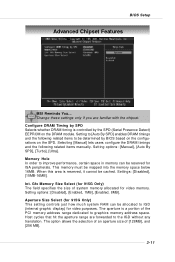
BIOS Setup Advanced Chipset Features MSI Reminds You... Setting options: [Manual], [Auto By SPD], [Turbo], [Ultra]. This memory must be cached. Int. Selecting [Manual] lets users configure the DRAM timings and ... only if you are forwarded to IGD (internal graphic display) for ISA peripherals. Configure DRAM Timing by SPD Selects whether DRAM timing is controlled by BIOS based on the configurations on the DRAM module. W hen this area is a portion of the PCI memory address range dedicated to [Auto By SPD] enables...
BIOS Setup Advanced Chipset Features MSI Reminds You... Setting options: [Manual], [Auto By SPD], [Turbo], [Ultra]. This memory must be cached. Int. Selecting [Manual] lets users configure the DRAM timings and ... only if you are forwarded to IGD (internal graphic display) for ISA peripherals. Configure DRAM Timing by SPD Selects whether DRAM timing is controlled by BIOS based on the configurations on the DRAM module. W hen this area is a portion of the PCI memory address range dedicated to [Auto By SPD] enables...
User Guide
Page 48
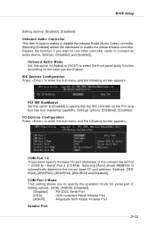
... has bus mastering capability. Onboard Audio Controller This item is used to enable or disable the onboard Azalia (Audio Codec) controller. Settings: [Disabled] and [Enabled]. BIOS Setup Setting options: [Enabled], [Disabled].
... has bus mastering capability. Onboard Audio Controller This item is used to enable or disable the onboard Azalia (Audio Codec) controller. Settings: [Disabled] and [Enabled]. BIOS Setup Setting options: [Enabled], [Disabled].


