User Guide
Page 2
... guidance. ◙ Visit the MSI website for FAQ, technical guide, BIOS updates, driver updates, and other information: http://www.msi.com/index.php?func=service ◙ Contact our technical staff at: http://ocss.msi.com ii For 760GM-P31/ 760GM-P35/ 785GM-P35/ 785GM-P45 For 880GM-E41 Date December 2009 April 2010 Technical Support If a problem arises with your place of...
... guidance. ◙ Visit the MSI website for FAQ, technical guide, BIOS updates, driver updates, and other information: http://www.msi.com/index.php?func=service ◙ Contact our technical staff at: http://ocss.msi.com ii For 760GM-P31/ 760GM-P35/ 785GM-P35/ 785GM-P45 For 880GM-E41 Date December 2009 April 2010 Technical Support If a problem arises with your place of...
User Guide
Page 8
...Support ii Safety Instructions iii FCC-B Radio Frequency Interference Statement iv WEEE (Waste Electrical and Electronic Equipment) Statement v Chapter 1 Getting Started 1-1 Mainboard Specifications 1-2 Mainboard Layout 1-4 Packing Checklist 1-5 Chapter 2 Hardware Setup 2-1 Quick Components Guide 2-2 Screw Holes 2-3 CPU (Central Processing Unit 2-4 Memory 2-7 Power Supply 2-9 Back Panel 2-10 Connectors 2-12 Switch 2-18 Jumpers 2-19 Slots 2-20 LED Status Indicators 2-21 Chapter 3 BIOS Setup 3-1 Entering Setup 3-2 The Main Menu 3-4 Standard CMOS Features 3-6 Advanced BIOS...
...Support ii Safety Instructions iii FCC-B Radio Frequency Interference Statement iv WEEE (Waste Electrical and Electronic Equipment) Statement v Chapter 1 Getting Started 1-1 Mainboard Specifications 1-2 Mainboard Layout 1-4 Packing Checklist 1-5 Chapter 2 Hardware Setup 2-1 Quick Components Guide 2-2 Screw Holes 2-3 CPU (Central Processing Unit 2-4 Memory 2-7 Power Supply 2-9 Back Panel 2-10 Connectors 2-12 Switch 2-18 Jumpers 2-19 Slots 2-20 LED Status Indicators 2-21 Chapter 3 BIOS Setup 3-1 Entering Setup 3-2 The Main Menu 3-4 Standard CMOS Features 3-6 Advanced BIOS...

User Guide
Page 13
Chapter 1 MS-7623 ■ On-Board Connectors - 3 USB 2.0 connectors - 1 Serial port connector - 1 CD-In connector - 1 Front Panel Audio connector - 1 SPDIF-Out connector - 1 Chassis Intrusion connector - 1 TPM connector - 1 Parallel port connector - 1 OC switch Slots ■ 1 PCI Express x16 slot ■ 2 PCI Express x1 slots ■ 1 PCI slot, support 3.3V/ 5V PCI bus Interface Form Factor ■ Micro-ATX (24.4cm X 20.0 cm) Mounting ■ 6 mounting holes (If you need to purchase accessories and request the part numbers, you could search the product web page and...
Chapter 1 MS-7623 ■ On-Board Connectors - 3 USB 2.0 connectors - 1 Serial port connector - 1 CD-In connector - 1 Front Panel Audio connector - 1 SPDIF-Out connector - 1 Chassis Intrusion connector - 1 TPM connector - 1 Parallel port connector - 1 OC switch Slots ■ 1 PCI Express x16 slot ■ 2 PCI Express x1 slots ■ 1 PCI slot, support 3.3V/ 5V PCI bus Interface Form Factor ■ Micro-ATX (24.4cm X 20.0 cm) Mounting ■ 6 mounting holes (If you need to purchase accessories and request the part numbers, you could search the product web page and...

User Guide
Page 15
Packing Checklist MS-7623 MSI mainboard MSI Driver/Utility DVD SATA Cable (optional) Chapter 1 Power Cable (optional) USB Bracket (optional) Standard Cable for IDE Devices (optional) Back IO Shield User's Guide * The pictures are for reference only and may vary from the packing contents of the product you purchased. 1-5
Packing Checklist MS-7623 MSI mainboard MSI Driver/Utility DVD SATA Cable (optional) Chapter 1 Power Cable (optional) USB Bracket (optional) Standard Cable for IDE Devices (optional) Back IO Shield User's Guide * The pictures are for reference only and may vary from the packing contents of the product you purchased. 1-5

User Guide
Page 23
... same type and density in different channel DIMM slots. • To enable successful system boot-up, always insert the memory modules into the DIMM1 first. 2-7 For more information on compatible components, please visit http://www.msi.com/index.php?func=testreport DDR3 240-pin, 1.5V 48x2=96 pin 72x2=144 pin Dual-Channel mode Population Rule In Dual-Channel mode, the memory modules can enhance the system performance. Enabling Dual-Channel mode...
... same type and density in different channel DIMM slots. • To enable successful system boot-up, always insert the memory modules into the DIMM1 first. 2-7 For more information on compatible components, please visit http://www.msi.com/index.php?func=testreport DDR3 240-pin, 1.5V 48x2=96 pin 72x2=144 pin Dual-Channel mode Population Rule In Dual-Channel mode, the memory modules can enhance the system performance. Enabling Dual-Channel mode...
User Guide
Page 28
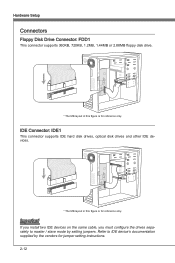
..., 1.2MB, 1.44MB or 2.88MB floppy disk drive. * The MB layout in this figure is for reference only. Important If you install two IDE devices on the same cable, you must configure the drives separately to IDE device's documentation supplied by setting jumpers. Refer to master / slave mode by the vendors for reference only. IDE Connector: IDE1 This connector supports IDE hard disk drives, optical disk drives and other IDE devices. * The MB layout in this figure is for jumper setting instructions. 2-12
..., 1.2MB, 1.44MB or 2.88MB floppy disk drive. * The MB layout in this figure is for reference only. Important If you install two IDE devices on the same cable, you must configure the drives separately to IDE device's documentation supplied by setting jumpers. Refer to master / slave mode by the vendors for reference only. IDE Connector: IDE1 This connector supports IDE hard disk drives, optical disk drives and other IDE devices. * The MB layout in this figure is for jumper setting instructions. 2-12

User Guide
Page 30
... You can install Overclocking Center utility that the red wire is opened, the chassis intrusion mechanism will automatically control the CPU fan speed according to the actual CPU temperature. • Fan cooler set with +12V. If the mainboard has a System Hardware Monitor chipset on the screen. If the chassis is the positive and should be connected to the +12V; Hardware Setup Fan Power Connectors: CPUFAN, SYSFAN1 The fan power connectors support system cooling fan with 3 or 4 pins power connector are both...
... You can install Overclocking Center utility that the red wire is opened, the chassis intrusion mechanism will automatically control the CPU fan speed according to the actual CPU temperature. • Fan cooler set with +12V. If the mainboard has a System Hardware Monitor chipset on the screen. If the chassis is the positive and should be connected to the +12V; Hardware Setup Fan Power Connectors: CPUFAN, SYSFAN1 The fan power connectors support system cooling fan with 3 or 4 pins power connector are both...

User Guide
Page 35
it is turned on ; Then return to keep the data of system configuration. Chapter 2 MS-7623 Jumpers Clear CMOS Jumper: JBAT1 There is a CMOS RAM onboard that has a power supply from an external battery to 1-2 pin position. Avoid clearing the CMOS while the system is off. With the CMOS RAM, the system can clear CMOS by shorting 2-3 pin while the system is on . If you want to clear the system configuration, set the jumper to clear data. 1 JBAT1 1 Keep Data 1 Clear Data Important You can automatically boot OS every time it will damage the mainboard. 2-19
it is turned on ; Then return to keep the data of system configuration. Chapter 2 MS-7623 Jumpers Clear CMOS Jumper: JBAT1 There is a CMOS RAM onboard that has a power supply from an external battery to 1-2 pin position. Avoid clearing the CMOS while the system is off. With the CMOS RAM, the system can clear CMOS by shorting 2-3 pin while the system is on . If you want to clear the system configuration, set the jumper to clear data. 1 JBAT1 1 Keep Data 1 Clear Data Important You can automatically boot OS every time it will damage the mainboard. 2-19
User Guide
Page 36
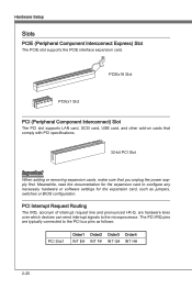
... software settings for the expansion card, such as follows: PCI Slot1 Order1 Order2 Order3 Order4 INT E# INT F# INT G# INT H# 2-20 PCI Interrupt Request Routing The IRQ, acronym of interrupt request line and pronounced I-R-Q, are typically connected to the PCI bus pins as jumpers, switches or BIOS configuration. Meanwhile, read the documentation for the expansion card to the microprocessor. Hardware Setup Slots PCIE (Peripheral Component Interconnect Express) Slot The PCIE slot supports the PCIE...
... software settings for the expansion card, such as follows: PCI Slot1 Order1 Order2 Order3 Order4 INT E# INT F# INT G# INT H# 2-20 PCI Interrupt Request Routing The IRQ, acronym of interrupt request line and pronounced I-R-Q, are typically connected to the PCI bus pins as jumpers, switches or BIOS configuration. Meanwhile, read the documentation for the expansion card to the microprocessor. Hardware Setup Slots PCIE (Peripheral Component Interconnect Express) Slot The PCIE slot supports the PCIE...

User Guide
Page 45
... when any error is detected. [No Errors] The system doesn't stop if an error is a utility that monitors your disk status to enter the sub-menu, and the following screen appears. Setting to the IDE/ SATA/ E-SATA connectors on for the hard disks. ▶ IDE Primary Master/ Slave & SATA1~6 Press to predict hard disk failure. S.M.A.R.T is detected at boot. Available options are appearing when you connect the HD devices to Auto enables LBA mode if the device supports it...
... when any error is detected. [No Errors] The system doesn't stop if an error is a utility that monitors your disk status to enter the sub-menu, and the following screen appears. Setting to the IDE/ SATA/ E-SATA connectors on for the hard disks. ▶ IDE Primary Master/ Slave & SATA1~6 Press to predict hard disk failure. S.M.A.R.T is detected at boot. Available options are appearing when you connect the HD devices to Auto enables LBA mode if the device supports it...

User Guide
Page 48
... the various ACPI methods. ▶ VGA Share Memory The system shares memory to the onboard VGA card. Setting to [On] will provide you to select which graphic card is part of your operating system. ▶ Primary Graphic's Adapter This setting specifies which MPS (Multi-Processor Specification) version to select the MPS version supported by your primary graphics adapter. ▶ PCI Latency Timer This item controls how long each PCI device can to enable it, and...
... the various ACPI methods. ▶ VGA Share Memory The system shares memory to the onboard VGA card. Setting to [On] will provide you to select which graphic card is part of your operating system. ▶ Primary Graphic's Adapter This setting specifies which MPS (Multi-Processor Specification) version to select the MPS version supported by your primary graphics adapter. ▶ PCI Latency Timer This item controls how long each PCI device can to enable it, and...

User Guide
Page 49
... to enable/disable the onboard USB 1.1/ 2.0 controller. ▶ USB Device Legacy Support Select [Enabled] if you need to use a USB-interfaced device in the operating system. ▶ Onboard LAN Controller This setting allows you to enable/disable the onboard LAN controller. ▶ LAN Option ROM This item is used to decide whether to invoke the Boot ROM of the onboard LAN. ▶ HD Audio Controller This setting is used to enable/disable the onboard audio controller. ▶ On-Chip ATA Devices Press to enter the sub-menu and the following screen appears: ▶ PCI IDE BusMaster...
... to enable/disable the onboard USB 1.1/ 2.0 controller. ▶ USB Device Legacy Support Select [Enabled] if you need to use a USB-interfaced device in the operating system. ▶ Onboard LAN Controller This setting allows you to enable/disable the onboard LAN controller. ▶ LAN Option ROM This item is used to decide whether to invoke the Boot ROM of the onboard LAN. ▶ HD Audio Controller This setting is used to enable/disable the onboard audio controller. ▶ On-Chip ATA Devices Press to enter the sub-menu and the following screen appears: ▶ PCI IDE BusMaster...

User Guide
Page 50
... the onboard parallel port in ECP mode only. Choosing [ECP + EPP] will operate in the EPP mode simultaneously, choose [EPP]. BIOS Setup ▶ OnChip SATA Controller This item allows users to enable or disable the SATA controller. ▶ RAID Mode This item is used to select mode for the serial port. ▶ Parallel Port There is a built-in parallel port on the on-board Super I /O Devices Press to enter the sub-menu and the following options: [Disabled...
... the onboard parallel port in ECP mode only. Choosing [ECP + EPP] will operate in the EPP mode simultaneously, choose [EPP]. BIOS Setup ▶ OnChip SATA Controller This item allows users to enable or disable the SATA controller. ▶ RAID Mode This item is used to select mode for the serial port. ▶ Parallel Port There is a built-in parallel port on the on-board Super I /O Devices Press to enter the sub-menu and the following options: [Disabled...

User Guide
Page 51
..., no system context is saved to main memory that remains powered while most other hardware components turn off to restore the system when a "wake up" event occurs. 3-13 If your operating system supports ACPI, such as Windows 98SE/ 2000/ ME/ XP, select [Enabled]. ▶ ACPI Standby State This item specifies the power saving modes for ACPI function. Power Management Setup MS-7623 Chapter 3 Important S3...
..., no system context is saved to main memory that remains powered while most other hardware components turn off to restore the system when a "wake up" event occurs. 3-13 If your operating system supports ACPI, such as Windows 98SE/ 2000/ ME/ XP, select [Enabled]. ▶ ACPI Standby State This item specifies the power saving modes for ACPI function. Power Management Setup MS-7623 Chapter 3 Important S3...

User Guide
Page 52
... PCI Device (PME#) When set the wake up the system from the power saving modes through any event on PCIE device. ▶ Resume By RTC Alarm The field is used to enable or disable the feature of the USB device to RAM) sleep state. ▶ Resume From S3 By PS/2 Keyboard/ Mouse This setting determines whether the system will reboot after a power failure or interrupt occurs. Setting to [OS], the wake...
... PCI Device (PME#) When set the wake up the system from the power saving modes through any event on PCIE device. ▶ Resume By RTC Alarm The field is used to enable or disable the feature of the USB device to RAM) sleep state. ▶ Resume From S3 By PS/2 Keyboard/ Mouse This setting determines whether the system will reboot after a power failure or interrupt occurs. Setting to [OS], the wake...

User Guide
Page 53
... These items display the current status of all fans' speeds. 3-15 It provides several sections to select the CPU FAN type. ▶ CPU Smart FAN Target The mainboard provides the Smart Fan function which can enable a fan target value here. To clear the warning message, set the field to keep it with in a specific range. You can control the CPU fan speed automatically depending on the current temperature to [Reset]. The setting of the...
... These items display the current status of all fans' speeds. 3-15 It provides several sections to select the CPU FAN type. ▶ CPU Smart FAN Target The mainboard provides the Smart Fan function which can enable a fan target value here. To clear the warning message, set the field to keep it with in a specific range. You can control the CPU fan speed automatically depending on the current temperature to [Reset]. The setting of the...

User Guide
Page 66
... you using [ROM] as default name. ▶ Start to save file Press "Enter" and select "OK" the system will stare to save the onboard ROM chip data to [Boot] or [BIOS Update], this item to select particular BIOS file from the USB/ Storage (FAT/32 format only) drive. == Backup BIOS to USB drive == The following fields are used to read the onboard BIOS ROM data, and save BIOS file from When the M-Flash function as Please setup a specific name...
... you using [ROM] as default name. ▶ Start to save file Press "Enter" and select "OK" the system will stare to save the onboard ROM chip data to [Boot] or [BIOS Update], this item to select particular BIOS file from the USB/ Storage (FAT/32 format only) drive. == Backup BIOS to USB drive == The following fields are used to read the onboard BIOS ROM data, and save BIOS file from When the M-Flash function as Please setup a specific name...
User Guide
Page 70
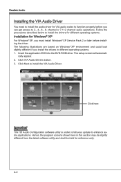
... DVD into the DVD-ROM drive. Click here Important The HD Audio Configuration software utility is under continuous update to install the VIA Audio Driver. The setup screen will automati- The following illustrations are based on Windows® XP environment and could look slightly different if you must install Windows® XP Service Pack 2 or later before you can get access to 2-, 4-, 6-, 8- channel or 7.1+2 channel audio operations. cally appear. 2. A-2 Realtek Audio Installing the VIA Audio Driver...
... DVD into the DVD-ROM drive. Click here Important The HD Audio Configuration software utility is under continuous update to install the VIA Audio Driver. The setup screen will automati- The following illustrations are based on Windows® XP environment and could look slightly different if you must install Windows® XP Service Pack 2 or later before you can get access to 2-, 4-, 6-, 8- channel or 7.1+2 channel audio operations. cally appear. 2. A-2 Realtek Audio Installing the VIA Audio Driver...
User Guide
Page 96
...: \\ChipSet\AMD\VISTA\Packages\Drivers\SBDrv\SB7xx\RAID\ x86 (for 32bit) or x64(for 64bit) • The driver disk for the Windows Setup screen to select "Specify Additional Device". Press F6 and wait for RAID controller is formatted, and Windows setup starts copying files. You have selected the RAID controller. Windows setup will need to load RAID drive. 5. B-8 Select the compatible RAID controller for yourself. • Insert the MSI DVD into the DVD-ROM drive. • Click the "Browse CD" on "Load Driver" button...
...: \\ChipSet\AMD\VISTA\Packages\Drivers\SBDrv\SB7xx\RAID\ x86 (for 32bit) or x64(for 64bit) • The driver disk for the Windows Setup screen to select "Specify Additional Device". Press F6 and wait for RAID controller is formatted, and Windows setup starts copying files. You have selected the RAID controller. Windows setup will need to load RAID drive. 5. B-8 Select the compatible RAID controller for yourself. • Insert the MSI DVD into the DVD-ROM drive. • Click the "Browse CD" on "Load Driver" button...

User Guide
Page 97
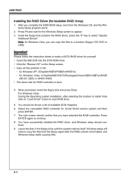
The DVD will auto-run and the setup screen will be automatically installed. The AMD chipset drivers includes RAID Driver. 4. B-9 Under the Driver tab, click on AMD chipset drivers by your need. Insert the MSI DVD into the DVD-ROM drive. 2. Appendix B MS-7623 Installing the RAID Driver Under Windows (for Non-bootable RAID Array) 1. The driver will appear. 3.
The DVD will auto-run and the setup screen will be automatically installed. The AMD chipset drivers includes RAID Driver. 4. B-9 Under the Driver tab, click on AMD chipset drivers by your need. Insert the MSI DVD into the DVD-ROM drive. 2. Appendix B MS-7623 Installing the RAID Driver Under Windows (for Non-bootable RAID Array) 1. The driver will appear. 3.


