
User Guide
Page 3
...Windows® 95/98/2000/NT/XP are registered trademarks of International Business Machines Corporation. Award® is a registered trademark of American Megatrends Inc. Revision History Revision V1.0 Revision History First release for PCB 1.X Date July 2003 Technical Support If a problem arises with your place of purchase or local distributor. Visit the MSI...Phoenix Technologies Ltd. Alternatively, please try the following help resources for FAQ, technical guide, BIOS updates, driver updates, and other information: http://www.msi.com.tw/ Contact our technical staff at: support@msi....
...Windows® 95/98/2000/NT/XP are registered trademarks of International Business Machines Corporation. Award® is a registered trademark of American Megatrends Inc. Revision History Revision V1.0 Revision History First release for PCB 1.X Date July 2003 Technical Support If a problem arises with your place of purchase or local distributor. Visit the MSI...Phoenix Technologies Ltd. Alternatively, please try the following help resources for FAQ, technical guide, BIOS updates, driver updates, and other information: http://www.msi.com.tw/ Contact our technical staff at: support@msi....
User Guide
Page 5
...Socket 478 2-4 Installing the CPU Fan 2-5 Memory 2-7 Memory Speed/CPU FSB Support Matrix 2-7 DDR Population Rules 2-7 Installing DDR Modules 2-8 Power Supply 2-9 ATX 20-Pin Power Connector: ATX1 2-9 ATX 12V Power Connector: JPW1 2-9 Back Panel 2-10 Mouse/Keyboard Connector 2-11 Serial Port Connectors: COMA & JCOM1 2-11 VGA Connector (for 865GM3 Series only 2-11 Parallel Port Connector: LPT1 2-13 LAN Jack: 10/100Mbps LAN (for 865PEM2 Series) or Gigabit LAN (for 865GM3 Series 2-13 IEEE1394 Port (Optional for 865PEM2 Series only 2-14 v Getting Started 1-1 Mainboard Specifications...
...Socket 478 2-4 Installing the CPU Fan 2-5 Memory 2-7 Memory Speed/CPU FSB Support Matrix 2-7 DDR Population Rules 2-7 Installing DDR Modules 2-8 Power Supply 2-9 ATX 20-Pin Power Connector: ATX1 2-9 ATX 12V Power Connector: JPW1 2-9 Back Panel 2-10 Mouse/Keyboard Connector 2-11 Serial Port Connectors: COMA & JCOM1 2-11 VGA Connector (for 865GM3 Series only 2-11 Parallel Port Connector: LPT1 2-13 LAN Jack: 10/100Mbps LAN (for 865PEM2 Series) or Gigabit LAN (for 865GM3 Series 2-13 IEEE1394 Port (Optional for 865PEM2 Series only 2-14 v Getting Started 1-1 Mainboard Specifications...

User Guide
Page 9
... chipset - AC'97 2.3 interface. - Supports both ACPI and legacy APM power management. h Three 32-bit v2.3 Master PCI bus slots (support 3.3v/5v PCI bus interface). Can connect up to 3.2GHz. PCI Master v2.3. - Slots h One AGP slot supports 8x/4x at 0.8V (AGP 3.0) or 4x at 1.5V (3.3V not supported). MS-6763 M-ATX Mainboard Mainboard Specifications CPU h Supports Intel® P4 Northwood (Socket 478) processors. I/O APIC. - Up to four Ultra ATA drives. Supports DDR 400/333/266 memory...
... chipset - AC'97 2.3 interface. - Supports both ACPI and legacy APM power management. h Three 32-bit v2.3 Master PCI bus slots (support 3.3v/5v PCI bus interface). Can connect up to 3.2GHz. PCI Master v2.3. - Slots h One AGP slot supports 8x/4x at 0.8V (AGP 3.0) or 4x at 1.5V (3.3V not supported). MS-6763 M-ATX Mainboard Mainboard Specifications CPU h Supports Intel® P4 Northwood (Socket 478) processors. I/O APIC. - Up to four Ultra ATA drives. Supports DDR 400/333/266 memory...
User Guide
Page 19
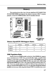
... modules must be installed onboard. Users may occur. 2-7 Each DIMM slot supports up to a maximum size of different type and density on the slots. Users can work respectively for single-channel DDR, but there are necessary while using dual-channel DDR (Please refer to meet their own needs. Hardware Setup Memory The mainboard provides four 184-pin unbuffered PC3200/PC2700/ PC2100 DDR DIMMs and supports the memory size up to 4GB...
... modules must be installed onboard. Users may occur. 2-7 Each DIMM slot supports up to a maximum size of different type and density on the slots. Users can work respectively for single-channel DDR, but there are necessary while using dual-channel DDR (Please refer to meet their own needs. Hardware Setup Memory The mainboard provides four 184-pin unbuffered PC3200/PC2700/ PC2100 DDR DIMMs and supports the memory size up to 4GB...

User Guide
Page 23
... Indicate VGA Connector (for 865GM3 Series only) The mainboard provides a DB 15-pin female connector to connect a VGA monitor. 5 1 15 11 VGA Connector (DB 15-pin) Pin Signal Description 1 RED 2 GREEN 3 BLUE 4 N/C 5 GND 6 GND 7 GND 8 GND 9 +5V 10 GND 11 N/C 12 SDA 13 Horizontal Sync 14 Vertical Sync 15 SCL 2-11 All ports are 16550A high speed communication ports that send/receive 16 bytes FIFOs. Hardware Setup Serial Port Connectors: COMA...
... Indicate VGA Connector (for 865GM3 Series only) The mainboard provides a DB 15-pin female connector to connect a VGA monitor. 5 1 15 11 VGA Connector (DB 15-pin) Pin Signal Description 1 RED 2 GREEN 3 BLUE 4 N/C 5 GND 6 GND 7 GND 8 GND 9 +5V 10 GND 11 N/C 12 SDA 13 Horizontal Sync 14 Vertical Sync 15 SCL 2-11 All ports are 16550A high speed communication ports that send/receive 16 bytes FIFOs. Hardware Setup Serial Port Connectors: COMA...

User Guide
Page 28
... be short. To clear the warning, you must enter the BIOS setting and clear the status. 2-16 JCI1 GND CINTRU 1 Floppy Disk Drive Connector: FDD1 The mainboard provides a standard floppy disk drive connector that supports 360K, 720K, 1.2M, 1.44M and 2.88M floppy disk types. MS-6763 M-ATX Mainboard Connectors The mainboard provides connectors to connect to 2-pin connector chassis switch. If the chassis is connected to FDD, IDE HDD, case, audio, LAN, USB Ports, and CPU/System fans. FDD1 Chassis Intrusion Switch Connector: JCI1 (Optional) This connector is open, the switch will...
... be short. To clear the warning, you must enter the BIOS setting and clear the status. 2-16 JCI1 GND CINTRU 1 Floppy Disk Drive Connector: FDD1 The mainboard provides a standard floppy disk drive connector that supports 360K, 720K, 1.2M, 1.44M and 2.88M floppy disk types. MS-6763 M-ATX Mainboard Connectors The mainboard provides connectors to connect to 2-pin connector chassis switch. If the chassis is connected to FDD, IDE HDD, case, audio, LAN, USB Ports, and CPU/System fans. FDD1 Chassis Intrusion Switch Connector: JCI1 (Optional) This connector is open, the switch will...

User Guide
Page 34
... Microphone power 4 AUD_VCC Filtered +5V used by analog audio circuits 5 AUD_FPOUT_R Right channel audio signal to front panel 6 AUD_RET_R Right channel audio signal return from front panel 7 NC No connection 8 KEY No pin 9 AUD_FPOUT_L Left channel audio signal to the front panel audio and is compliant with Intel® Front Panel I/O Connectivity Design Guide. MS-6763 M-ATX Mainboard Front Panel Audio Connector: JAUD1 The JAUD1 front panel audio connector allows you don't want to connect to the front audio header, pins...
... Microphone power 4 AUD_VCC Filtered +5V used by analog audio circuits 5 AUD_FPOUT_R Right channel audio signal to front panel 6 AUD_RET_R Right channel audio signal return from front panel 7 NC No connection 8 KEY No pin 9 AUD_FPOUT_L Left channel audio signal to the front panel audio and is compliant with Intel® Front Panel I/O Connectivity Design Guide. MS-6763 M-ATX Mainboard Front Panel Audio Connector: JAUD1 The JAUD1 front panel audio connector allows you don't want to connect to the front audio header, pins...

User Guide
Page 37
... shorting 2-3 pin while the system is a CMOS RAM on . This section will damage the mainboard. 2-25 Then return to 1-2 pin position. Avoid clearing the CMOS while the system is turned on board that has a power supply from external battery to keep the data of jumpers. Clear CMOS Jumper: JBAT1 There is off. You can automatically boot OS every time it will explain how to change your motherboard's function through the use...
... shorting 2-3 pin while the system is a CMOS RAM on . This section will damage the mainboard. 2-25 Then return to 1-2 pin position. Avoid clearing the CMOS while the system is turned on board that has a power supply from external battery to keep the data of jumpers. Clear CMOS Jumper: JBAT1 There is off. You can automatically boot OS every time it will explain how to change your motherboard's function through the use...

User Guide
Page 38
... supported). Its main processing is a specially designed network, audio, or modem riser card for the throughput demands of 3D graphics. AGP is an interface specification designed for ATX family motherboards. CNR is done through software and controlled by the motherboard's chipset. 2-26 PCI (Peripheral Component Interconnect) Slots The PCI slots allow you unplug the power supply first. MS-6763 M-ATX Mainboard Slots The motherboard provides one AGP slot, three 32-bit PCI bus slots, and one CNR slot. AGP Slot PCI Slots...
... supported). Its main processing is a specially designed network, audio, or modem riser card for the throughput demands of 3D graphics. AGP is an interface specification designed for ATX family motherboards. CNR is done through software and controlled by the motherboard's chipset. 2-26 PCI (Peripheral Component Interconnect) Slots The PCI slots allow you unplug the power supply first. MS-6763 M-ATX Mainboard Slots The motherboard provides one AGP slot, three 32-bit PCI bus slots, and one CNR slot. AGP Slot PCI Slots...
User Guide
Page 44
Frequency/Voltage Control Use this menu to set user and supervisor passwords. Load Default Setting Use this menu to specify your CPU, fan, overall system status, etc. PC Health Status This menu shows the status of your settings for optimal system operations. BIOS Setup PNP/PCI Configurations This entry appears if your system supports PnP/PCI. Exit Without Saving Abandon all changes and exit setup. 3-5 Save & Exit Setup Save changes to load the BIOS default values that are factory settings for frequency/voltage control. Monitor function...
Frequency/Voltage Control Use this menu to set user and supervisor passwords. Load Default Setting Use this menu to specify your CPU, fan, overall system status, etc. PC Health Status This menu shows the status of your settings for optimal system operations. BIOS Setup PNP/PCI Configurations This entry appears if your system supports PnP/PCI. Exit Without Saving Abandon all changes and exit setup. 3-5 Save & Exit Setup Save changes to load the BIOS default values that are factory settings for frequency/voltage control. Monitor function...

User Guide
Page 46
... is not matched or listed, you enter improper information for a keyboard error. If the controller of the storage device. Capacity The formatted size of HDD interface is detected. Precomp Write precompensation. Available options are : All Errors No Errors All, But Keyboard All, But Diskette All, But Disk/Key The system stops when any detected error. Video The setting controls the type of video adapter used for any error is CD-ROM, the selection shall...
... is not matched or listed, you enter improper information for a keyboard error. If the controller of the storage device. Capacity The formatted size of HDD interface is detected. Precomp Write precompensation. Available options are : All Errors No Errors All, But Keyboard All, But Diskette All, But Disk/Key The system stops when any detected error. Video The setting controls the type of video adapter used for any error is CD-ROM, the selection shall...

User Guide
Page 49
.../3rd boot device. Setting to Off will allow users to set the Num Lock status when the system is controlled by Port92 or chipset specific method resulting in faster system performance. When the default value Fast is selected, the Gate A20 is to use the arrow keys on . Setting options: Disabled, Enabled. Typematic Delay (Msec) This item allows you to boot from the Network drive. MS-6763 M-ATX Mainboard USB-HDD The...
.../3rd boot device. Setting to Off will allow users to set the Num Lock status when the system is controlled by Port92 or chipset specific method resulting in faster system performance. When the default value Fast is selected, the Gate A20 is to use the arrow keys on . Setting options: Disabled, Enabled. Typematic Delay (Msec) This item allows you to boot from the Network drive. MS-6763 M-ATX Mainboard USB-HDD The...
User Guide
Page 50
... floppy drive. A password prompt appears every time when the computer is powered on or when end users try to run in the Integrated Peripherals menu. HDD S.M.A.R.T. Report No FDD For WIN95 For compatibility with DRAM greater than 64MB. To find out which MPS (Multi-Processor Specification) version to run Setup. BIOS Setup Security Option This specifies the type of your operating system. Settings: 1.4, 1.1. This gives you to be used...
... floppy drive. A password prompt appears every time when the computer is powered on or when end users try to run in the Integrated Peripherals menu. HDD S.M.A.R.T. Report No FDD For WIN95 For compatibility with DRAM greater than 64MB. To find out which MPS (Multi-Processor Specification) version to run Setup. BIOS Setup Security Option This specifies the type of your operating system. Settings: 1.4, 1.1. This gives you to be used...
User Guide
Page 55
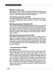
... used to enable or disable the DMA transfer function of IDE hard drives under certain operating systems that the onboard IDE interface supports. MS-6763 M-ATX Mainboard IDE DMA Transfer Access This setting is possible only if your system software both SATA and PATA controllers are combined to support a maximum of 2 IDE drives in each channel separately. The settings are : Auto, Disabled. **On-Chip Serial ATA Setting** On-Chip Serial ATA This setting controls the Serial ATA controller on the operating system installed. When set...
... used to enable or disable the DMA transfer function of IDE hard drives under certain operating systems that the onboard IDE interface supports. MS-6763 M-ATX Mainboard IDE DMA Transfer Access This setting is possible only if your system software both SATA and PATA controllers are combined to support a maximum of 2 IDE drives in each channel separately. The settings are : Auto, Disabled. **On-Chip Serial ATA Setting** On-Chip Serial ATA This setting controls the Serial ATA controller on the operating system installed. When set...

User Guide
Page 57
... Audio Auto allows the motherboard's BIOS to use different controller cards to connect audio connectors, set the field to enable/disable the onboard Gigabit LAN controller. If not, the onboard audio controller will be disabled. Setting options: Disabled, Enabled. USB 2.0 Controller This setting is used to enable/disable the onboard USB 2.0 controller. USB Controller This setting is used to enable/disable the onboard USB 1.1 controller. If you 're using any USB keyboard/mouse driver installed, such as Windows 2000/XP/ME. Setting options: Disabled, Enabled. MS-6763 M-ATX Mainboard...
... Audio Auto allows the motherboard's BIOS to use different controller cards to connect audio connectors, set the field to enable/disable the onboard Gigabit LAN controller. If not, the onboard audio controller will be disabled. Setting options: Disabled, Enabled. USB 2.0 Controller This setting is used to enable/disable the onboard USB 2.0 controller. USB Controller This setting is used to enable/disable the onboard USB 1.1 controller. If you 're using any USB keyboard/mouse driver installed, such as Windows 2000/XP/ME. Setting options: Disabled, Enabled. MS-6763 M-ATX Mainboard...

User Guide
Page 58
... Disabled. Disable the controller if you wish to use other controller cards to connect a modem. Settings: Auto, Disabled. Super IO Device Press to enter the sub-menu and the following screen appears: Onboard FDC Controller Select Enabled if your system has a floppy disk controller (FDD) installed on FDC or the system has no floppy drive, select Disabled in this field. Onboard Serial Port 1/Port 2 Select an address and corresponding interrupt for 865PE) This setting is used to enable/disable the onboard 10/100Mbps LAN controller. Onboard LAN Device...
... Disabled. Disable the controller if you wish to use other controller cards to connect a modem. Settings: Auto, Disabled. Super IO Device Press to enter the sub-menu and the following screen appears: Onboard FDC Controller Select Enabled if your system has a floppy disk controller (FDD) installed on FDC or the system has no floppy drive, select Disabled in this field. Onboard Serial Port 1/Port 2 Select an address and corresponding interrupt for 865PE) This setting is used to enable/disable the onboard 10/100Mbps LAN controller. Onboard LAN Device...
User Guide
Page 60
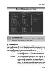
.../ files is saved to main memory that remains powered while most other hardware components turn off to save energy. If your BIOS supports S3 sleep mode. The information stored in this section are : S1 (POS) The S1 sleep mode is lost (CPU or chipset) and hardware maintains all system context. In this field. Options are available only when your operating system supports ACPI, such as Windows 98SE, Windows...
.../ files is saved to main memory that remains powered while most other hardware components turn off to save energy. If your BIOS supports S3 sleep mode. The information stored in this section are : S1 (POS) The S1 sleep mode is lost (CPU or chipset) and hardware maintains all system context. In this field. Options are available only when your operating system supports ACPI, such as Windows 98SE, Windows...

User Guide
Page 62
... By PCI Card, USB KB Wake-Up From S3 These fields specify whether the system will be shut off button. Soft-Off by Alarm. CPU THRM-Throttling The item allows you press the power button, the computer enters the suspend/sleep mode, but if the button is pressed for Resume By Alarm. Resume By Alarm The field is used to configure the power button function. BIOS Setup Suspend Mode...
... By PCI Card, USB KB Wake-Up From S3 These fields specify whether the system will be shut off button. Soft-Off by Alarm. CPU THRM-Throttling The item allows you press the power button, the computer enters the suspend/sleep mode, but if the button is pressed for Resume By Alarm. Resume By Alarm The field is used to configure the power button function. BIOS Setup Suspend Mode...

User Guide
Page 64
... any changes to operate at speeds nearing the speed the CPU itself uses when communicating with its special components. PNP OS Installed When set to Yes, BIOS will initialize all the PnP cards. Select Enabled to automatically configure 3-25 Resources Controlled By The Award Plug and Play BIOS has the capacity to reset Extended System Configuration Data (ESCD) when you exit Setup if you leave this field Disabled. BIOS Setup PNP/PCI Configurations...
... any changes to operate at speeds nearing the speed the CPU itself uses when communicating with its special components. PNP OS Installed When set to Yes, BIOS will initialize all the PnP cards. Select Enabled to automatically configure 3-25 Resources Controlled By The Award Plug and Play BIOS has the capacity to reset Extended System Configuration Data (ESCD) when you exit Setup if you leave this field Disabled. BIOS Setup PNP/PCI Configurations...

User Guide
Page 66
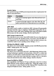
CPU Warning Temperature If the CPU temperature reaches the upper limit preset in this setting, the warning mechanism will be shut down. 3-27 When the processor reaches the temperature you to prevent the CPU overheat problem. BIOS Setup PC Health Status This section shows the status of the monitored hardware devices/components such as CPU voltages, temperatures and all fans' speeds. Chassis Intrusion Detect The field enables or disables the feature of...
CPU Warning Temperature If the CPU temperature reaches the upper limit preset in this setting, the warning mechanism will be shut down. 3-27 When the processor reaches the temperature you to prevent the CPU overheat problem. BIOS Setup PC Health Status This section shows the status of the monitored hardware devices/components such as CPU voltages, temperatures and all fans' speeds. Chassis Intrusion Detect The field enables or disables the feature of...

